Dispersion blue-shift in an aperiodic Bragg reflection waveguide
Abstract
A particular feature of an aperiodic design of cladding of Bragg reflection waveguides to demonstrate a dispersion blue-shift is elucidated. It is made on the basis of a comparative study of dispersion characteristics of both periodic and aperiodic configurations of Bragg mirrors in the waveguide system, wherein for the aperiodic configuration three procedures for layers alternating, namely Fibonacci, Thue–Morse and Kolakoski substitutional rules are considered. It was found out that, in a Bragg reflection waveguide with any considered aperiodic cladding, dispersion curves of guided modes appear to be shifted to shorter wavelengths compared to the periodic configuration regardless of the modes polarization.
keywords:
photonic crystals , Bragg reflection waveguide , aperiodic structure , dispersion characteristicsPACS:
42.25.Bs , 42.70.Qs , 42.79.Gn , 42.82.Et1 Introduction
As is known, in contrast with conventional optical waveguides based on the effect of the total internal reflection inside a high-index core [1], distinctive features of Bragg reflection waveguides are influenced by a multilayered configuration of their composite cladding [2], which has a form of a stack of alternating high- and low-index layers. Indeed, such a composition of cladding leads to formation of photonic bandgaps in the spectra of the multilayered system resulting in light confinement within a low-index core which is usually considered to be an air gap. Such photonic bandgap guidance brings several attractive features to the waveguide characteristics [3, 4], in particular, since most of light is guided inside a low-index core, losses and nonlinear effects can be significantly suppressed compared to the conventional high-index guiding waveguides.
Furthermore, even in the simplest symmetric configuration of Bragg reflection waveguides there is a set of unique optical features that are unattainable in conventional waveguides since the former ones are highly dispersive due to their complicate geometry (rather than just to their material composition). As such features we can mention that in Bragg reflection waveguides [5, 6]: (i) each guided mode has several cutoff points, which results in ability to design a waveguide supported only the high-order modes instead of the fundamental one; (ii) there is a possibility to lose a specific mode due to shrinking of the photonic bandgap into point; (iii) some specific modes with negative order can appear when a system consists of a thin enough guiding layer. On the other hand, Bragg reflection waveguides exhibit an extra degree of freedom for optimizing their optical characteristics through utilization of particular designs of the cladding, among which an asymmetric mirrors design [7, 8], layers chirping in the cladding [9, 10], and placing the matched layers between the core and cladding [11] may be referred.
In this paper we report on the other possibility of tuning the operation bandwidth of Bragg reflection waveguides by applying an another special design to the multilayered cladding. Our motivation in this study is in follows. If we have a look from the viewpoint of practical applications, both the number of layers in the cladding and their thicknesses should be as small as possible. It is due to the fact that the production of waveguides with thinner layers requires fewer amount of materials for deposition, and thus less time for the process. At the same time, it contradicts with the technological limits that are imposed on the possibility of producing layers with a very small thicknesses. Besides, it is difficult to reach precise step-index profiles with sharp boundaries, and this problem is more significant for structures with the thinnest layers. In this context, it is of interest to find such a configuration of layers in the cladding, which would allow one to shift the operation frequency of the waveguide into the higher band without changing number of layers and their thicknesses.
It is obvious that through the solution of an optimization problem [12] it is possible to find the best spatial distribution of layers in a random sequence that produces a maximal shift, however, in this consideration we prefer to deal with deterministically ordered structures instead of completely random ones, since in the first case we are able to definitely predict the spectral properties of the system [13, 14, 15, 16, 17], i.e. the width and position of stopbands on the frequency scale, which are key characteristics that are taken into consideration when designing the Bragg reflection waveguides. As noted in our previous papers [18, 19, 20, 21], stopbands in the spectra of aperiodic structures can appear to be shifted in comparison with the stopbands in the spectra of periodic structures assuming the same material parameters and number of layers in the multilayered systems. Therefore, in this paper, in order to provide a comparative study, we consider spectral features and dispersion characteristics of a Bragg reflection waveguide having either periodic or aperiodic configuration of layers in the cladding. For an aperiodic configuration we have a choice between three well known aperiodic chains produced through substitution rules of Fibonacci [22], Thue–Morse [23], and Kolakoski [24] sequences.
2 Theoretical Description
We consider a Bragg reflection waveguide (Fig. 1a) that is made of a low-index core layer (in particular, an air gap) sandwiched between two identical either periodic or aperiodic one-dimensional Bragg mirrors formed by stacking together layers of two different sorts and , which have thicknesses , and refractive indices and , respectively. The numbers of constitutive layers of each sort are defined as and . The structure inhomogeneity (i.e. the variation of the refractive index) extends along the -axis, and in this direction the system is finite, i.e. we suppose that mirrors on either side of the core layer consist of a finite number of the constitutive layers. In other two directions and the structure is invariant and infinite. In such a geometry the axis of symmetry of the structure under study corresponds to the middle of the core layer which is at the line , where the core layer has thickness and refractive index .
Therefore, we study a Bragg reflection waveguide having a core layer with thickness , where . As constituents for the cladding composition we utilize a combination of layers made of GaAs and oxidized AlAs, whose refractive indices at the given wavelength are and , respectively. The thicknesses and are chosen to be nm for GaAs layers and nm for AlAs-oxide layers in order to provide the operation bandwidth to be within the first telecommunication window.
As an aperiodic configuration three alternative designs of the waveguide’s mirrors are investigated. Thus, a comparative study between the waveguides with the multilayered cladding altered according to the substitutional rules of Fibonacci [22], Thue–Morse [23], and Kolakoski [24] sequences is provided (see, A).
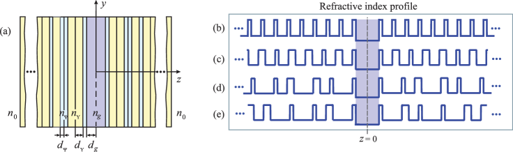 |
In the chosen structure configuration, each guided mode of TE polarization or TM polarization propagates along the -axis with its own propagation constant . As the mirrors on each side of the waveguide core layer are the same (i.e. the Bragg reflection waveguide is symmetrical about the -axis, , as it is depicted in Fig. 1 b-e), the equations for waves travelling back and forth inside the channel regardless of the type of polarization can be joined on the boundaries and into the next system
| (1) |
from which the relation between amplitudes can be found
| (2) |
Here is the transverse wavenumber in the core, is introduced as an effective refractive index for each particular guided mode, is the free space wavenumber, and is the complex reflection coefficient of the Bragg mirror which is depended on the wave polarization. The reflection coefficient can be derived engaging the transfer matrix formalism [18, 19, 20] (see, B).
Eliminating amplitudes and from system (1), the dispersion equation for the guided modes of the Bragg reflection waveguide is obtained as
| (3) |
This equation is further solved numerically to find out a function of the propagation constant versus frequency . The resulting propagation constant is sought in the field of complex numbers due to the existence of intrinsic losses in the waveguide constitutive materials and energy leakage through the outermost layers because the number of layers in the Bragg mirrors is a finite quantity.
The proper selection of the constitutive materials suggests the preference of substances with low internal losses. According to [26] the imaginary parts of the dielectric constants of the chosen GaAs and oxidized AlAs are negligibly small within the wavelength region of interest. Therefore, the main source of losses in the Bragg reflection waveguides under consideration is the energy leakage through their finite cladding. These losses can be estimated via the expression [5]:
| (4) |
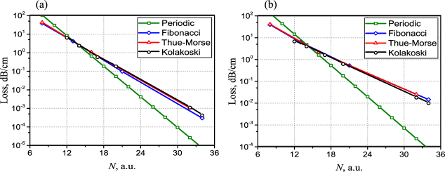 |
From our estimation for the lowest modes presented in Fig. 2 it follows that the level of losses decreases exponentially with (see, also discussions on this matter in [5, 27]), and leakage of the TM mode is much greater than that of the TE mode. The leakage is also greater for the waveguides with an aperiodic arrangement of the cladding compared with the periodic system. Thus, the criterion of smallness of the imaginary part of when classifying the waveguide modes can be satisfied by setting the number to an appropriate high value.
For the symmetric waveguides all guided modes can be divided into symmetric and anti-symmetric ones. Without loss of generality, the overall field amplitude in the middle line of the core can be reduced to unity or zero for symmetric and anti-symmetric modes, respectively. Then the field in the core can be normalized by setting and , where the upper sign ‘’ is related to symmetric modes, while the lower sign ‘’ is related to anti-symmetric ones, respectively.
3 Numerical Results: Solution Analysis
Our goal here is to demonstrate a dispersion blue-shift of guided modes in a Bragg reflection waveguide that appears in the system having aperiodically arranged layers in the cladding. In order to reveal the mentioned blue-shift we provide a comparative study of the waveguide with either periodic or aperiodic configuration of the cladding. It is supposed that the periodic Bragg mirrors consist of a finite number of layers () which is enough to provide the desired level of reflection in order to guarantee that the propagation constant is essentially real. Obviously, the number of layers of each sort and in the periodic system is the same (). Further three aperiodic designs are investigated. In the first aperiodic configuration the mirrors are formed by stacking together layers and according to the Fibonacci generation rule on its eighth generation stage. At this stage there are layers in the system with different number of layers of each sort and ( and ). In the second configuration, the cladding is arranged according to the Thue–Morse substitution rule on its six generation stage which corresponds to the system with the same number of layers as in the periodic configuration (). There is the same number of layers of each sort and in this system (). As the third configuration, the cladding is considered to be an aperiodic structure arranged according to the Kolakoski generation scheme on its twentieth generation stage. For such a configuration the total number of layers coincides with those ones of the periodic and Thue–Morse structures (), but there is different number of layers of each sort and ( and ).
For clarity, we should note that the total number of layers and the number of layers of each sort within the deterministically aperiodic multilayered system depend on the generation stage, and for certain schemes it is impossible to obtain a given number of layers in the system (e.g., using the Fibonacci substitution rule it is impossible to obtain the system consisting of layers). Thereby, a complete coincidence in the layers numbers on the earlier generation stages exists only for periodic and Thue–Morse configurations, for these structures the different spatial order of the layers is the only difference between them. On the other hand, in the infinite limit of the generation stage the numbers of layers of each sort and in the periodic, Thue–Morse and Kolakoski structures take on the same values, while for the Fibonacci structure the numbers of layers can be calculated from the formulas [19] obtained using the generating functions technique [wilf_genfunct_2013]: , , where is the generation stage (), and . Here is the well known golden mean value [13].
In Fig. 3 both band diagrams and dispersion curves for TE and TM polarizations are presented. They are calculated for the waveguide whose core layer is an air gap surrounded by the cladding with either periodic (a, b) or aperiodic (c-h) arrangement. Here, regions colored in light green correspond to the bands within which light can propagate through the multilayered structure (passbands), whereas uncolored areas correspond to the bands where the level of reflection is high enough (), therefore they can be identified as stopbands.
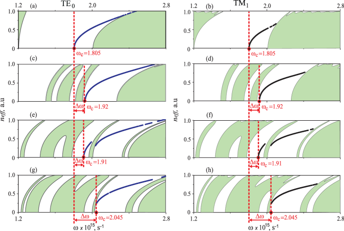 |
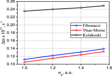
In this figure the guided modes are indicated by a set of colored (blue and black) points, and it is evident that all these guided modes appear only within the bands where the level of reflection riches high values () (i.e. within the stopbands). One can conclude from Fig. 3, that the dispersion curve of each guided mode is terminated at the stopbands edge at either maximal or minimal allowable value of , at which there is a mode cutoff. Besides, it can be observed that for all aperiodic waveguide configurations the dispersion curves appear to be shifted to shorter wavelength (i.e. they acquire some blue-shift which is marked in figures as ) as compared to the dispersion curves related to the structure with the periodic arrangement. In fact this blue shift depends very little on the refractive index of the core layer as it is depicted in Fig. 4 (assuming of course that is smaller than the refractive index of the first layer in the mirrors).
 |
We should note that generally stopbands which carry the above-mentioned modes are also shifted to shorter wavelength. It is a consequence of the fact that in contrast to periodic multilayered systems which have the main stopband centered around , aperiodic structures are characterized by a set of (pseudo) stopbands which are distributed symmetrically around this wavelength accompanied with highly localized transmission peaks in the vicinity of the wavelength .
Evidently, the dispersion shift appears due to different spatial orders of the constitutive layers in the considered waveguide’s configurations. Thus, the difference in order of arrangement of layers results in the optical thickness changing of particular layers in the structure, since some repetitions in a row of layers of the same sort or can appear in the aperiodic sequences that reduces the number of layers’ interfaces within the system compared to the periodic one. The formation of layers with doubled thicknesses and produces the enlarged phase shift , that leads to a change in the total reflection spectrum of the mirror, because the shape of the reflection spectrum of a multilayered structure depends on the phase modulation of each layer as . If we mark the phase modulation for the doubled layers as , then the reflectivity can be factorized as the product of two contributions [29], where the function takes into account the value of the reflectivity due to the refractive index contrast, and is a shape factor that represents the different optical paths of the light inside the layers. In our case, indeed, changes in result in the dispersion shift, since the substitution takes place.
It is noticed in Fig. 3 that the longest shift is observed for the Bragg reflection waveguide whose cladding is formed according to the Kolakoski generation rule due to the greater number of the doubled layers in the mirrors compared to other considered systems. For the given waveguide parameters, in wavelengths, the maximal shift is observed to be about nm.
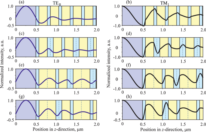 |
In order to prove that the obtained dispersion curves are associated to the same waveguide modes, the field profiles inside the waveguide for the corresponding field components ( for TE mode, and for TM mode) are calculated at the same frequency ( s-1) which are reported in Fig. 5. These mode-field profiles are plotted after applying normalization of the field magnitude on its maximal value within the core. From these figures it follows, that the field of the fundamental TE0 mode appears to be well confined within the central air-guiding core. The degree of this confinement can be estimated via calculation of the confinement factor , where is related to field components and for TE modes and TM modes, respectively. Thus, the confinement factor related to the TE0 mode manifests rather high values for all discussed configurations (see, values of given in the caption of Fig. 3) and, especially, the highest values and are obtained for the periodic and aperiodic Kolakoski configurations of the cladding. Besides, the field intensity of the fundamental mode decays rapidly within the first few pairs of the constitutive layers of the cladding as it is depicted in Fig. 3. At the same time, the field of TM1 mode appears to be less confined within the core layer, thus, as was already mentioned, the field leakage is higher for this polarization.
4 Conclusions
To conclude, a dispersion blue-shift in a Bragg reflection waveguide consisting of an aperiodic design of layers in the cladding compared to the periodic design is demonstrated. The strength of this blue-shift is investigated for three aperiodic multilayered systems, namely for those alternated according to Fibonacci, Thue–Morse and Kolakoski substitution rules. It is recognized that the longest shift is observed for the Bragg reflection waveguide whose cladding is formed according to the Kolakoski sequence.
In order to prove that the considered dispersion curves are associated to the same waveguide modes, both the field profile inside the waveguide and the confinement factor for each mode are calculated. It is found out that the highest confinement factor can be achieved in the Kolakoski structure among other aperiodic designs.
We argue that the design of cladding in the form of an aperiodic structure gives rise to change in the dispersion characteristics, resulting in the shift of cutoff wavelengths of guided modes toward the shorter wavelength regardless of their polarization.
Appendix A Aperiodic Orders
In optics, a standard algorithm for arranging aperiodic photonic structures is usually based on a certain symbolic substitution rule (i.e. on a specific substitution rule that operates on a finite alphabet which consists of a set of letters ). In practical realizations each letter can be associated with a particular constitutive block (e.g. with a dielectric or semiconductor layer) in a resulting photonic structure. In this regard, substitution sequences that act upon a two-letter alphabet are especially important. Such algorithms can be reduced to following:
| (5) |
where and can be any string of letters and .
Fibonacci sequence is obtained via iteration of the rule [22], as
| (6) |
resulting in the letters chain .
The generation rule of the Kolakoski sequence is similar to those ones of Fibonacci and Thue–Morse sequences and can be based on two symbols substitution. Namely, the sequence can be obtained by starting with as a seed and iterating the following two substitutions [24]
| (8) |
where and can be any string of letters and ; denotes a run of ’s, i.e., ( times). In this paper we examine the case when and , so the letters chain appears. Remarkably, using the Kolakoski substitutional rule (8) it is possible to obtain any value of the total number of letters in the resulting chain by changing its generation stage and starting letter of the sequence.
Appendix B Transfer Matrix Description
The plane monochromatic waves of TE () and TM () polarizations can be defined in a particular -th layer ( of the sequence in the form
| (9) |
where
| (10) |
and and are the field amplitudes, and are the wave admittances, is the wavenumber in free space, and is the transverse wavenumber which takes on discrete values in each slab and can be written as
| (11) |
Here takes on values for the core layer, and and for the and cladding layers, respectively.
The field amplitudes for the structure input and output are evaluated as [18, 19, 20]
| (12) |
where the total transfer matrix is obtained by multiplying in the appropriate order the matrices corresponding to each layer in the structure.
The matrices and are the particular transfer matrices of rank 2 of the and layers in cladding with their corresponding thicknesses and . They are
| (13) |
where and () are the transfer matrices of the layer interfaces with outer half-spaces, and are the propagation matrices through the corresponding layer. The elements of the matrices and are determined by solving the boundary-value problem related to the field components (9):
| (14) |
| (15) |
where the upper sign ‘’ relates to the TE wave, while the lower sign ‘’ relates to the TM wave.
Finally, the reflection coefficient of the layer stack is determined by the expression
| (16) |
where are the elements of the transfer matrix , and is the phase of the reflected light.
References
-
[1]
A. Snyder, J. Love,
Optical Waveguide
Theory, Science paperbacks, Springer, 1983.
URL https://books.google.com.ua/books?id=gIQB_hzB0SMC -
[2]
P. Yeh, A. Yariv,
Bragg
reflection waveguides, Optics Communications 19 (3) (1976) 427–430.
doi:http://dx.doi.org/10.1016/0030-4018(76)90115-2.
URL http://www.sciencedirect.com/science/article/pii/0030401876901152 -
[3]
S. Johnson, M. Ibanescu, M. Skorobogatiy, O. Weisberg, T. Engeness,
M. Soljacic, S. Jacobs, J. Joannopoulos, Y. Fink,
Low-loss
asymptotically single-mode propagation in large-core omniguide fibers, Opt.
Express 9 (13) (2001) 748–779.
doi:10.1364/OE.9.000748.
URL http://www.opticsexpress.org/abstract.cfm?URI=oe-9-13-748 -
[4]
P. Russell,
Photonic
crystal fibers, Science 299 (5605) (2003) 358–362.
arXiv:http://www.sciencemag.org/content/299/5605/358.full.pdf, doi:10.1126/science.1079280.
URL http://www.sciencemag.org/content/299/5605/358.abstract -
[5]
B. R. West, A. S. Helmy,
Properties of
the quarter-wave Bragg reflection waveguide: Theory, J. Opt. Soc. Am. B
23 (6) (2006) 1207–1220.
doi:10.1364/JOSAB.23.001207.
URL http://josab.osa.org/abstract.cfm?URI=josab-23-6-1207 -
[6]
J. Li, K. S. Chiang,
Guided modes of
one-dimensional photonic bandgap waveguides, J. Opt. Soc. Am. B 24 (8)
(2007) 1942–1950.
doi:10.1364/JOSAB.24.001942.
URL http://josab.osa.org/abstract.cfm?URI=josab-24-8-1942 -
[7]
J. Li, K. S. Chiang,
Light
guidance in a photonic bandgap slab waveguide consisting of two different
Bragg reflectors, Optics Communications 281 (23) (2008) 5797–5803.
doi:http://dx.doi.org/10.1016/j.optcom.2008.08.040.
URL http://www.sciencedirect.com/science/article/pii/S0030401808008432 -
[8]
Y. Li, Y. Xi, X. Li, W.-P. Huang,
A
single-mode laser based on asymmetric Bragg reflection waveguides, Opt.
Express 17 (13) (2009) 11179–11186.
doi:10.1364/OE.17.011179.
URL http://www.opticsexpress.org/abstract.cfm?URI=oe-17-13-11179 -
[9]
B. Nistad, M. W. Haakestad, J. Skaar,
Dispersion
properties of planar Bragg waveguides, Optics Communications 265 (1)
(2006) 153–160.
doi:http://dx.doi.org/10.1016/j.optcom.2006.03.014.
URL http://www.sciencedirect.com/science/article/pii/S0030401806002252 -
[10]
B. Pal, S. Ghosh, R. Varshney, S. Dasgupta, A. Ghatak,
Loss and dispersion
tailoring in 1D photonics band gap Bragg reflection waveguides: Finite
chirped claddings as a design tool, Optical and Quantum Electronics
39 (12–13) (2007) 983–993.
doi:10.1007/s11082-007-9160-y.
URL http://dx.doi.org/10.1007/s11082-007-9160-y - [11] P. Abolghasem, A. S. Helmy, Matching layers in Bragg reflection waveguides for enhanced nonlinear interaction, Quantum Electronics, IEEE Journal of 45 (6) (2009) 646–653. doi:10.1109/JQE.2009.2013118.
-
[12]
J.-S. I, Y. Park, H. Jeon,
Optimal design for
one-dimensional photonic crystal waveguide, J. Lightwave Technol. 22 (2)
(2004) 509.
URL http://jlt.osa.org/abstract.cfm?URI=jlt-22-2-509 -
[13]
E. Maciá, The role of
aperiodic order in science and technology, Reports on Progress in Physics
69 (2) (2006) 397.
URL http://stacks.iop.org/0034-4885/69/i=2/a=R03 -
[14]
O. Shramkova, Y. Olkhovskiy,
Electromagnetic
wave transmission and reflection by a quasi-periodic layered semiconductor
structure, Physica B: Condensed Matter 406 (8) (2011) 1415 – 1419.
doi:http://dx.doi.org/10.1016/j.physb.2011.01.041.
URL http://www.sciencedirect.com/science/article/pii/S0921452611000780 -
[15]
V. I. Fesenko, V. R. Tuz, P. P. Rocha Garcia, I. A. Sukhoivanov,
Dispersion properties of a
one-dimensional aperiodic OmniGuide structure, Proc. SPIE 9200 (2014)
920017–920017–7.
doi:10.1117/12.2060525.
URL http://dx.doi.org/10.1117/12.2060525 - [16] V. I. Fesenko, V. R. Tuz, I. A. Sukhoivanov, Terahertz aperiodic multilayered structure arranged according to the Kolakoski sequence, in: M. F. Pereira, O. Shulika (Eds.), Terahertz and Mid Infrared Radiation: Detection of Explosives and CBRN (Using Terahertz), NATO Science for Peace and Security Series B: Physics and Biophysics, 2014.
- [17] V. I. Fesenko, Omnidirectional reflection from generalized Kolakoski multilayers, Progress In Electromagnetics Research M 41 (2015) 33–41. doi:10.2528/PIERM14121103.
-
[18]
V. R. Tuz, Optical
properties of a quasi-periodic generalized Fibonacci structure of chiral
and material layers, J. Opt. Soc. Am. B 26 (4) (2009) 627–632.
doi:10.1364/JOSAB.26.000627.
URL http://josab.osa.org/abstract.cfm?URI=josab-26-4-627 -
[19]
V. Tuz, V. Kazanskiy,
Electromagnetic
scattering by a quasiperiodic generalized multilayer Fibonacci structure
with grates of magnetodielectric bars, Waves in Random and Complex Media
19 (3) (2009) 501–508.
doi:10.1080/17455030902780445.
URL http://www.tandfonline.com/doi/abs/10.1080/17455030902780445 -
[20]
V. R. Tuz, O. D. Batrakov,
Localization and
polarization transformation of waves by a symmetric and asymmetric modified
Fibonacci chiral multilayer, Journal of Modern Optics 57 (21) (2010)
2114–2122.
doi:10.1080/09500340.2010.522261.
URL http://dx.doi.org/10.1080/09500340.2010.522261 - [21] V. I. Fesenko, Aperiodic birefringent photonic structures based on Kolakoski sequence, Waves in Random and Complex Media 24 (2) (2014) 174–190. doi:10.1080/17455030.2014.890764.
-
[22]
M. Kohmoto, B. Sutherland, K. Iguchi,
Localization of
optics: Quasiperiodic media, Phys. Rev. Lett. 58 (1987) 2436–2438.
doi:10.1103/PhysRevLett.58.2436.
URL http://link.aps.org/doi/10.1103/PhysRevLett.58.2436 -
[23]
N.-h. Liu, Propagation
of light waves in Thue-Morse dielectric multilayers, Phys. Rev. B 55
(1997) 3543–3547.
doi:10.1103/PhysRevB.55.3543.
URL http://link.aps.org/doi/10.1103/PhysRevB.55.3543 -
[24]
B. Sing,
Kolakoski
sequences - an example of aperiodic order, Journal of Non-Crystalline Solids
334 (2004) 100–104.
doi:http://dx.doi.org/10.1016/j.jnoncrysol.2003.11.021.
URL http://www.sciencedirect.com/science/article/pii/S0022309303008524 -
[25]
V. I. Fesenko, V. R. Tuz, O. V. Shulika, I. A. Sukhoivanov,
Dispersion
properties of a nanophotonic Bragg waveguide with finite aperiodic
cladding, ArXiv e-prints arXiv:1510.03470.
URL http://adsabs.harvard.edu/abs/2015arXiv151003470F -
[26]
S. Adachi,
GaAs,
AlAs, and AlxGa1-xAs: Material parameters for use in research
and device applications, Journal of Applied Physics 58 (3) (1985) R1–R29.
doi:http://dx.doi.org/10.1063/1.336070.
URL http://scitation.aip.org/content/aip/journal/jap/58/3/10.1063/1.336070 -
[27]
A. Argyros,
Guided
modes and loss in Bragg fibres, Opt. Express 10 (24) (2002) 1411–1417.
doi:10.1364/OE.10.001411.
URL http://www.opticsexpress.org/abstract.cfm?URI=oe-10-24-1411 -
[28]
M. Özer, A. Čenys, Y. Polatoglu, G. Hacibekiroglu, E. Akat,
A. Valaristos, A. Anagnostopoulos,
Bifurcations
of Fibonacci generating functions, Chaos, Solitons & Fractals 33 (4)
(2007) 1240–1247.
doi:http://dx.doi.org/10.1016/j.chaos.2006.01.095.
URL http://www.sciencedirect.com/science/article/pii/S0960077906001457 -
[29]
L. Moretti, I. Rea, L. De Stefano, I. Rendina,
Periodic
versus aperiodic: Enhancing the sensitivity of porous silicon based optical
sensors, Applied Physics Letters 90 (19) (2007) 191112.
doi:http://dx.doi.org/10.1063/1.2737391.
URL http://scitation.aip.org/content/aip/journal/apl/90/19/10.1063/1.2737391