Authors’ Instructions
Supporting the monitoring of the verification process of critical systems’software
Abstract
Critical software systems face stringent requirements in safety, security, and reliability due to the circumstances surrounding their operation. Safety and security have progressively gained importance over the years due to the integration of hardware with software-intensive deployments that introduce additional sources of errors. It is, then, necessary to follow high-quality exhaustive software development processes that besides the needed development activities to increase safety and security also integrate techniques to increase the reliability of the software development process itself. In practice, the use of automated techniques for the verification of the verification process is, however, not sufficiently wide spread. This is mainly due to the high cost of the required techniques and to their degree of complexity when adjusting to the different norms and regulations. This work presents an approach for comprehensive management of the verification processes; the approach allows engineers to monitor and control the project status regarding the applicable standards. This approach has been validated through its implementation in a tool and its application to real projects.
1 Introduction
Failure avoidance is of paramount importance in critical software systems, needed to be considered in the first place as it has a direct impact on the safe operation. The main reasons for system failure are described in [3]. Around 44% of the failures are caused by wrong system specifications, and a 15% are introduced during the design and development phases. This means that over 60% of the failures can be avoided during design and development phases. Some of the most common errors are to start the verification process in the final phase of the project or not to take into account the safety from the beginning. On the other hand, the cost associated to certain bugs and reingeneering can be unacceptably high. In general, the cost of the development activities is directly related to the required safety level. Although this cost tends to be restrained, it can be doubled if the development follows an approach that does not consider safety requirements.
There are a number of regulations and norms such as DO-178B[4] and DO-278[5] that define the set of objectives to achieve an acceptable level of safety.
In the scope of critical software projects, there is a process of continuous investigation in order to reduce costs and development time, that usually includes the definition of methodologies and process automation and/or optimization techniques. The usage of adequate tools that support them is essential in order to optimize the monitoring of the processes. Using a V- Model, the processes or phases identified in DO-178B[4] and DO-278[5] are planning, requirements, design, coding and integration, integration, verification, configuration management, quality assurance and certification/approval liaison. Some of these phases are integral processes and must be performed through all the software life cycle.
Due to the specific requirements of the safety monitoring processes, it is usual that the status information for all the involved processes is very complex; information is typically contained in different places, and it is responsibility of several teams. This situation makes the status monitoring to be a difficult task to perform, prone to causing several undesirable effects such as missing information, or bad dimensioning of the development situation. In critical systems developments, this may lead to unsafe situations that have to be avoided.
Current monitoring tools are, in practice, complex tool chains mostly supporting separate activity monitoring. Usually, the different views over the development progress are provided by distinct tools in a non collaborative environment. Since different critical software projects follow different norms, there are no tools that are able to be easily customized to adapt to different norms. For instance, embedded software installed in aircrafts (like cockpits, mission computers and others) is usually developed under DO-178B[4] while ground equipments (like navigation or surveillance radars) use DO-278[5]. In both cases, most of the processes are similar, but they are in fact different among themselves. For example, DO-278[5] introduces considerations about COTS software or adaptation data. Therefore, it is needed to take into account the particular characteristics of each norm, additional requirements introduced in each project, and possible changes in the applicable norm.
To increase the efficiency of development in critical software systems, it is required that norms are supported by flexible yet pragmatic and more powerful monitoring methodologies that can be flexible to adjust to different norms. A severe drawback of current methods and tools is that they do not fully support the definition and use of a consistent and uniform methodology for the monitoring of the verification activities for all projects, and they do not facilitate the compliance with regulatory requirements.
This paper describes an approach to improve the current practices of monitoring by providing a new methodology that covers the verification management activities in a collaborative environment to facilitate the integration with other life cycle process, and provide the possibility of future extensions. We present an approach that automates the process of monitoring by the integration of optimization mechanisms that includes all the information regarding the compliance statement of the applicable norm.
The paper is structured as follows. Section 1 presents an introduction and motivation for this work. Section 2 describes the related work in what concerns norms and practices used for monitoring. Section 3 describes the proposed approach that allows cross-norm monitoring of the verification. Section 4 presents the implementation of the methodology in a tool and its usage and results for a real-world critical software project. Section 5 concludes the paper.
2 Background and related work
2.1 Standards and engineering processes
There are several standards that define processes for the software development of critical systems. Most of these standards were initially guidelines describing an approach to the regulatory requirements; they have later become de facto regulations due to their widespread adoption. Some of these standards are defined in Table 1.
| Doc. No. | Title | Description |
|---|---|---|
| ESARR6 | Eurocontrol Safety Regulatory Requirement 6 – Software in ATM Functional Systems, [7] | Applicable to ATM/CNS systems. Continuation of the framework defined in [8] for the software. Two accepted international standards used for compliance with it are [5] and [9]. |
| DO-178B | Software Considerations in Airborne Systems and Equipment Certification, [4] | One of the most accepted international standards. Used as a basis for [5]. Recently updated to [10], that includes additional objectives and it is complemented with the supplements [11], [12], [13] and [14]. |
| DO-278 | Guidelines for Communication, Navigation, Surveillance and Air Traffic Management, [5] | Provides guidelines for non-airborne CNS/ATM systems. It is intended to reuse the objectives included in DO-178B/ED-12B to the software contained in ATM/CNS systems, reviewing, modifying and expanding in some cases, them. This document has also been recently updated to [6] |
| IEC 61508 | Functional safety of electrical/ electronic/ programmable electronic safety-related systems, [1] | Industry automation. It is intended to be a safety standard applicable to all kinds of industry. Includes the complete safety life cycle. It has been used as a basis for other specific documents, as railway (CENELEC 50128[15]), automotive industries (ISO 26262[1]) or nuclear power plants (IEC 61513[2]) |
| CENELEC 50128 | Railway applications - Communications, signalling and processing systems, [15] | Standard applicable in the railway industry. Specifies the processes and technical requirements for the development of software for programmable electronic systems for use in railway control and protection applications |
| ISO 26262 | Road Vehicles - Functional Safety | Referred to the safety application in the automotive industry. Its objective is to assure the functional safety of a electric/electronic system of a motor vehicle. Developed from the [1] for its specific use in the automotive industry. |
| IEC 62304 | Medical device software - Software life cycle processes, Ref. [16] | This norm specifies the software life cycle requirements in medical devices |
On the other hand, there are a lot well-known models that define the software development process. Classical approaches include Waterfall development or the V-model, that offer a complete life-cycle approach with several phases.
The Waterfall model was introduced by Winston W. Royce in 1970 ([17]), although the term ”waterfall” was used for the first time by Bell and Thayer in 1976 [18]. This model defines the software development phases and the sequence among them. The end of a phase is checked through a revision that determines if the project can start the following phase or not. There is much emphasis on documentation to provide an adequate basis to further phases, improve the design and aid the accuracy of the information exchanged in the development.
The V-model can be considered an extension of the Waterfall model. It is not a sequence of phases moving in a linear way, but the representation of its process forms a ”V”. On its left side, the development phases are represented. On the right side, the verification phases can be found. The vertex of the ”V” is the coding phase. Criticisms to it are the lack of flexibility or ineffective testing methodology applied and difficult to be strictly applied for non-trivial projects. For example, requirements are not always clearly defined by the customer, and the development cannot wait to the clarification of all of them because of schedule constraints. In projects with dynamic, non-deterministic and continuously changing requirements it is difficult to establish accurate plans in the early stages, often leading to a waste of resources and a lot of rework due to this uncertainty. The Agile methods (Agile Manifesto [19]) appears like an adaptive, iterative and evolutionary development methodology. There are several agile software methods and process frameworks, like Scrum [20], Kanban [21], Extreme Programming (XP) [22], and Adaptive Software Development (ASD) [23], among others.
Other approaches try to balance the previous methodologies, to take advantage of their strenghts and compensate for their weaknesses, as described by Boehm and Turner in [24] and [26]. They support the idea of Brooks in his article [25], that building software is always hard and there is not a silver bullet because of its inherent properties: complexity, conformity, changeability and invisibility. Boehm and Turner propose a risk-based approach to be used in software projects to incorporate both agile and disciplined characteristics according to the project needs.
2.2 Missing elements for a more automated verification monitoring
The selection of a concrete development model often comes imposed by the company methodology, customer requirements or simply due to convenience. This is an additional handicap in order to introduce the standard requirements in the development strategies, and it becomes extremely important to be able to address as many development models as possible with the minimum impact in the applicable standard.
Regardless to the methodology used, it is necessary to monitor and control the status of the development activities, in order to check if the project objectives are being achieved and to make correction in the process if needed.
Within the scope of this work, and in order to improve the monitoring and control activity in software projects, the following goals are defined: (1) to cover the verification management activities, (2) to develop a collaborative environment, (3) to facilitate the integration with other life cycle processes and (4) to provide the possibility of future extensions and adaptation to new norms or processes.
At this point, it is important that the monitoring and control activities are as automated as possible, using the contributions of all actors involved in the project. This way, each actor needing information about the status of the project can find it almost immediately, which can contribute to reduce risks associated to the development.
Verification processes are typically achieved by the usage of non standardized tool chains combined with ad-hoc methods, practices and tools that constitute a competition between companies. These are typically set at the start of a project and have to be latter heavily modified if any change is produced or a different project is started. Therefore, it is not easy to obtain information about these and it is even more difficult to get hands on specific technology.
It is necessary to look for new solutions and mechanisms that contribute to reach the development objectives in a more effective way, increasing the reliability and safety required, reducing at the same time the risk and costs associated to the software development. Up to the best of our knowledge, there is no publicly available methodology (also supported by a tool) that provides a unifying framework for the monitoring activities, i.e., for the verification of the verification. The presented approach overcomes this.
3 Support for improvement of the monitoring of the verification process
This section describes the proposed approach that aims at improving and automating the monitoring of the activities involved in the verification process of critical software systems, by meeting the objectives described above. Figure 1 provides an overview of this methodology.
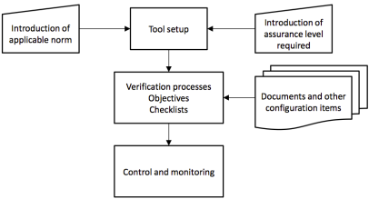
Our approach relies on the initial establishment of an assurance level and an applicable norm. The assurance level indicates the relation between a failure condition and its associated effects in the system. Failure conditions are classified into: catastrophic, hazardous, major, minor and no effect. Depending on the assurance level allocated to the software, the objectives to be reached are defined. For example, in case of DO-178B[4], level A is the most critical level and level E is the lowest criticality one; whereas for DO-278[5], AL1 is the most restrictive one and AL6 the least restrictive one.
Derived from several years of professional engineering on monitoring of verification activities for critical software systems in a wide range of critical software systems, our approach is based on the following concepts: the fundamental requirements to be met by the methodology, and a set of operational phases.
The methodology meets overall fundamental requirements, that indicate the important objectives to be achieved in a correct verification process. The requirements are precisely that: () the methodology has to support full collaboration among all actors of the verification process; and () the different phases of the methodology are carried out by specific project roles such as developers, project managers, or verifiers that have different activities to perform. As such, it defines the access and permissions policy that determine the actions that every role is able to perform. The methodology defines a minimum set of phases that must be simple in their conception in order to guarantee its applicability across projects. The phases determine the way in which the monitoring process itself takes place, defining a sequence of steps to execute in order to (1) initially establish; and later (2) carry out the monitoring of the verification activities. The methodology phases must allow an easy integration of different norms in the project (or across projects) to ensure that the software complies with the specific objectives.
3.1 Specification of the monitoring framework
This initial phase defines the baseline elements of the verification activities of the different software projects. The methodology supports simultaneous monitoring of different projects. For a given software project , a number of verification activities () take place to ensure the correctness of the software development with respect to a norm and an assurance level. A verification activity of a project , named , is an action carried out by at least one actor; this action consist of checking a set of predefined elements. For each project , an set must be defined. It is true that for two different projects and , it is not necessary that the set of elements of and is equal. As the software projects are alive, the baseline elements are managed and can dynamically change over time according to the identification of the specific project needs.

Some items must be specified (all in sets) that define the operational environment of the methodology, facilitating its use and applicability to specific projects and contexts. These items will be specified in section 3.2, as a part of the parametrization for the approach.
One of the essential specifications concerns the actors and their role. Default roles are: administrator, verification manager, verifier, developer, and reader. A reader has the sole possibility of accessing the status of the development and verification processes, and it is typically the role of project managers and technical managers. Developers have access to all information though they cannot modify the status of any item or comment. verifiers can introduce comments and observations about any configuration item registered for a specific process changing their status, and they can update the values of the verification processes and the configuration items and set their status. The verification manager has all permissions of the verification process and can update any of the elements.
3.2 Parameterization
This phase instantiates the above framework specifications that are particularized to manage the verification activities. The progress of the verification process of a project () is related to the actual progress of the verification activities in the different processes. (): . Progress of a project is monitored by defining and observing the status of the specified set of elements . When the verification process of project is completed then ; value indicate that there is still some comment (or non-conformity) that has not been addressed.
From each project , the following variables are extracted from the framework specifications of section 3.1:
-
•
Norm set and standards of applicability ().
-
•
Assurance level ().
-
•
Project characteristics relative to specific management issues are:
-
–
Life cycle () of the project. Example values (i.e., models) are presented in section 2.1.
-
–
The selected verification processes () to monitor the software development correctness in its different parts. Each process has an associated list of configuration items and process checklists that are registered for it that reflect important information to be checked in the software development.
-
–
-
•
The process checklists () for each . If referred to a given project, the project subindex can be eliminated.
-
•
The list of configuration items includes:
-
–
Set of documents () to be provided for a given project and norms and the status of the documents. For example, requirements or design documents.
-
–
The process document checklist () for a concrete document of project assigned to a specific verification process. If referring to a given project, it can be abbreviated eliminating the project subindex.
-
–
Set of observations () and their status that are specific information items of relevance.
-
–
-
•
Users () of project including their roles. Examples of values for user roles have been given in section 3.1.
Possible values for the above variables are later exemplified in a real project example in Table 2.
3.3 Assessment of verification status
As the goal of the methodology is to assist in the assessment of the project status that implies the compliance with the norm objectives, our approach provides several levels of control or views:
-
•
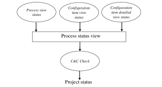
Project status view reflects the status for each verification process within the project. The project status is determined by the Consistency and Completeness Check, namely C&C algorithm (see Figure 3).
-
•
Verification process view reflects the status of the verification processes, including the process status view, configuration items status view and the view on the configuration items observations.
-
–
Process status view reflects the results of the review of process objectives according to a specific norm and assurance level, through a process checklist (see Figure 4).
-
–
Configuration items view shows a list of documents and other elements (source code, for example) that are determined by the used software life cycle standards, including the applicable assurance standard. It reflects the compliance status through the configuration items checklists and the observations view, described below (see Figure 5).
-
–
Configuration items observations view shows the status of the observations that contains the set of comments produced by the different actors of the verification process. Comments are referred to as non-conformities. This view has the purpose of recording the verification review, the undertaken actions and the status, in order to provide objective evidences of the verification process of each item (see Figure 6).
-
–


Each level provides information for the Consistency and Completeness check (C&C check) logic, which is shown below in Algorithm 1.
As an example of an objective defined by a norm that must be checked by the verification process, we may find ”low-level requirements comply with high-level requirements”. This such objective is shown in the verification of outputs of Software Design Process. If the verification actors detect that it is not met, a non-conformity is opened.
The overall status of the project is determined by the partial status of each process. In general, the process status can be either pending or completed:
A pending status is assigned when there is a negative answer to any question of the process or configuration items checklist or there is an opened comment for any of the configuration items.
4 Validation through a use case
The validation of the proposed approach is shown in this section firstly by presenting its practical implementation in a software tool based on PhP and Java; and secondly, by presenting a real critical software project example that has been specified and parametrized in a software tool. We show the monitoring of the project status through different monitoring views, finally showing the view over the observed non-conformities.
The practical use case over the tool allows to check the methodology utility and the management of the life cycle process of the software for a given norm.
The first step was to define a norm, the objectives, and basic checklists to cover the whole life cycle. Once all this information is introduced in the tool, it is possible to modify or extend it to be reused in other projects. All the processes are customizable for the users (verification actors), allowing the definition of the scope for each project.
The project that has been selected as an example for the tool validation is a real defence project that consists of the replacement of the cockpit display units of a military aircraft. To demonstrate that the software was correctly designed, verified and validated, the considerations provided by [4] were used as an acceptable means of compliance. According to the Functional Hazard Analysis (see [27]), the assurance level to be applied is DAL-B. The development life-cycle used was a ”V” model, and the phases defined in [4] were used. For each of these phases, the our approach was used. For the planning process, five plans (PSAC, SDP, SVP, SCMP and SQAP) and three standards (requirements, desing and coding) were developed, as required by [4].
| DO-178B[4] | |
|---|---|
| DAL-B | |
| V-Model | |
| Planning, requirements, design, coding&integration, integration, Verification of Verification | |
| Defined according to [4] | |
| Defined to cover [4] for each verification process | |
| Defined to cover [4] for each DO | |
| Defined according project organization and roles |
Once the project information was specified and parametrized according to Table 2, the monitoring process began where all actors used the supporting tool for the monitoring of all verification activities. Checklists for each configuration item were filled, showing their status and details. Observations about each item were registered in the tool. Results are shown in Figure 7 where different metrics about the non-conformities are found, separated by verification process. There were observations introduced regarding the plans and standards developed for the project; non-conformities were registered about the requirements, and regarding the design; non-conformities were registered in the coding and integration processes, related to the compliance with the coding standard. incidences were found during the execution of the tests, and were registered in the supporting tool for monitoring and representing the status of the integration. Eventually, non-conformities were detected in the verification of verification processes. Changes needed to the procedures where detected during the life cycle, and introduced in the tool, as part of the verification of verification process.

The main observations were focused on the need of including additional clarifications about some contents, like references to the development and verification tools, and the need of their qualification. Other comments refereed to the need of including additional information, or clarify the specified organization. In some cases, changes were needed such as in the software configuration management plan to address some processes required by the internal company policies. The observations of the certification authority were also introduced, becoming part of the information about the development process.
Regarding the development standards (requirements, design, and coding), there were not many observations given that standards are typically well known and applied in different projects. Still additional comments were brought due to the particularities of each project and improvements to be introduced.
For the requirements and design processes, the requirements document was introduced, filling the correspondent checklists and registering the observations. The requirements document is one of the most important one as requirements are used as the basis for (1) the design as they describe the required functionality; and (2) to define the tests to be performed in the corresponding phase. Consequently, there were more than of observations that involved changes in the original document, including some clarifications introduced by the author. In the review of this document, the applicable standard (Ref. [4]) and the requirements standard defined for the project were used.
The tool provided tangible evidences for the results of the verification process for each development process which serves as a basic reference for generate the Software Accomplishment Summary and System Safety Assessment. In these documents, it is necessary to include references to all the evidences needed for the development assurance level required. The data introduced in the tool are able to provide an evidence to the Certification Authorities of the performed work and compliance status.
4.1 Additional considerations critical software systems
The architecture of the software is of paramount importance in critical systems as it directly impacts the complexity of the final development and, therefore, its verification and testing. Critical software systems verification focuses heavily on temporal behavior applying real-time mechanisms ([29, 30, 31, 28, 39]). Other soft real-time domains rather provide quality of service mechanisms embedded in the software logic that accounds for mechanisms to allow dynamic execution whereas preserving timely properties ([36, 32, 38, 37, 40]). Verification of the properties of distributed software also related to newer domains as cloud ([33]), the characteristics of the middleware are integrated in the model ([35, 34]). Lastly, specific verification mechanisms are executed on-line in very specific contexts such as cyber-physical systems ([42, 41]).
5 Conclusions
The lack of information and the complexity of the applicable norms and processes in systems with safety requirements increases costs and difficulties to achieve requirements compliance. This paper has presented an approach that clarifies these processes, that is supported by a tool that facilitates the compliance with the safety requirements and the adoption of new regulations.
Due to the introduced information for the data items for each development phase, actors involved in the projects can know the software life cycle defined with a quick view of the tool. This directly implies a reduction in the training time of engineers. For each item it is possible to know the existing non conformities, which enables their early detection and correction by the responsible. In the tool, the collaboration is achieved through a web interface.
All information about the status of development and verification tasks is immediately accessible to actors, that provides knowledge about the work performed and the pending tasks. So, an estimation of the remaining activities can be calculated, which could lead to implement corrective actions and minimize the impact in project goals, decreasing the project risks.
The tool covers all the verification process according to the different levels. The supporting tool has managed two standards ([4] and [5]), covering a large scope of safety related projects. A set of documents and checklists for each develop phase and for document have been created, providing a basic framework to manage this kind of projects. It is possible to add additional documents at any time.
Finally, the methodology allows to follow any kind of development model. Thus, the objective about integration with other life cycle processes is fulfilled by the presented approach, including information about the development. The supporting tool provides possibilities of future growth, by extensions that include information about new norms or processes.
References
- [1] International Electrotechnical Commission (IEC). IEC 61508. Functional safety of electrical/electronic/programmable electronic safety-related systems. April 2010.
- [2] International Electrotechnical Commission (IEC). IEC 61503. Nuclear power plants. Instrumentation and control important to safety. General requirements for systems. Ed.2.0. August 2011.
- [3] Health and Safety Executive (HSE). Out of Control: Why Control Systems Go Wrong and How to Prevent Failure. Second edition. HSE Books. ISBN 978-0-7176-2192-7. 2003.
- [4] RTCA Inc. DO-178B. Software Considerations in Airborne Systems and Equipment Certification. RTCA Inc. / EUROCAE. DO-178B/ED-12B. 1992.
- [5] RTCA, EUROCAE. DO-278 / ED-109. Guidelines for Communication, Navigation, Surveillance, and Air Traffic Management (CNS/ATM) Systems Software Integrity Assurance. RTCA Inc. / EUROCAE. DO-278/ED-109. 3/5/2002.
- [6] RTCA Inc. / EUROCAE. DO-278A/ED-109A. Software Integrity Assurance Considerations for Communication, Navigation, Surveillance and Air Traffic Management (CNS/ATM) Systems. December 2011.
- [7] Eurocontrol. ESARR6. Eurocontrol Safety Regulatory Requirement 6 – Software in ATM Functional Systems. May 2010.
- [8] Eurocontrol. ESARR4. Eurocontrol Safety Regulatory Requirement 4 – Risk Assessment and Mitigation in ATM. April 2001.
- [9] EUROCAE. ED-153. Guidelines for ANS Software Safety Assurance. August 2009.
- [10] RTCA Inc. / EUROCAE. DO-178C / ED-12B. Software Considerations in Airborne Systems and Equipment Certification. December 2011.
- [11] RTCA Inc. / EUROCAE. DO-330 / ED-215. Software Tool Qualification Considerations. December 2011 - January 2012.
- [12] RTCA Inc. / EUROCAE. DO-331 / ED-216. Model-Based Development and Verification Supplement to DO-178C and DO-278A / Model-Based Development and Verification Supplement to ED-12B and ED-109A. December 2011 - January 2012.
- [13] RTCA Inc. / EUROCAE. DO-332 / ED-217. Object-Oriented Technology and Related Techniques Supplement to DO-178C and DO-278A / Object-Oriented Technology and Related Techniques Supplement to ED-12C and ED-109A. December 2011 - January 2012.
- [14] RTCA Inc. DO-333 / ED-218. Formal Methods Supplement to DO-178C and DO-278A / Model-Based Development and Verification Supplement to ED-12C and ED-109A. December 2011.
- [15] CENELEC. CENELEC 50128. Railway applications - Communications, signalling and processing systems. 2001.
- [16] IEC IEC 62304. Medical Device Software. May 2006.
- [17] W. Royce. Managing the Development of Large Software Systems: Concepts and Techniques In: Proceedings of IEEE WESCON, pp. 1-9. August, 1970.
- [18] T. E. Bell and T. A. Thayer. Requirements: Are they really a problem? In: Proceedings of the 2nd international conference on Software engineering, pp. 61-68. 1976.
- [19] K. Beck, et al. Manifesto for Agile Software Development Agile Alliance, 2001.
- [20] K. Schwaber, J. Sutherland. The Scrum GuideTM. The Definitive Guide to Scrum: The Rules of the Game Scrum.org and ScrumInc, 2014.
- [21] D. Anderson. Kanban - Successful Evolutionary Change for your Technology Business ISBN 0-9845214-0-2. Blue Hole Press, 2010.
- [22] D. Wells. Extreme Programming: A gentle introduction Available at: http://www.extremeprogramming.org [Last retrieved 14/01/2014]
- [23] J. A. Highsmith. Adaptive Software Development: A Collaborative Approach to Managing Complex Systems Dorset House Publishing Co Inc.,U.S. ISBN: 978-0-932633-40-8
- [24] B. Bohem, R. Turner. Balancing Agility and Discipline. A guide for the Perplexed Addison Wesley. ISBN 0-321-18612-5. 2004
- [25] F. P. Brooks No Silver Bullet - Essence and Accidents of Software Engineering. IEEE Computer. April 1987.
- [26] B. Boehm, R. Turner. Observations on balancing discipline and agility In: Proceedings of the Agile Development Conference, pp. 32-39. ISBN 0-7695-2013-8. 2003.
- [27] SAE International, Inc. Guidelines and Methods for Conducting the Safety Assessment Process on Civil Airborne Systems and Equipment. ARP4761. 1996.
- [28] J. Duenas, A. Alonso, W. Lopes Oliveira, M. Garcia, G. Leon. Software architecture assessment. In: Software architecture for product families: principles and practice. Addison-Wesley. 2000.
- [29] B. Bouyssounouse, et al. Programming languages and real-time systems. In: Embedded systems design: the ARTIST roadmap for research and development. Springer, 2005.
- [30] B. Bouyssounouse, et al. QoS Management. In: Embedded systems design: the ARTIST roadmap for research and development. Springer, 2005.
- [31] B. Bouyssounouse, et al. Adaptive real-time systems development. In: Embedded systems design: the ARTIST roadmap for research and development. Springer, 2005.
- [32] C. M. Otero Pérez, L. Steffens, P. van der Stok, S. van Loo, A. Alonso, J. Ruíz, R. J. Bril, M. García Valls. QoS-Based Resource Management for Ambient Intelligence. In: Ambient Intelligence: Impact on Embedded Sytem Design, pp. 159–182. Kluwer Academic Publishers. 2003.
- [33] M. García Valls, T. Cucinotta, C. Lu. Challenges in real-time virtualization and predictable cloud computing. Journal of Systems Architecture, vol.60(9), pp736–740. 2014.
- [34] M. García Valls, R. Baldoni. Adaptive middleware design for CPS: Considerations on the OS, resource managers, and the network run-time. Proc. Workshop on Adaptive and Reflective Middleware (ARM). 2015.
- [35] M. García-Valls, L. Fernández Villar, I. Rodríguez López. iLAND: An enhanced middleware for real-time reconfiguration of service oriented distributed real-time systems IEEE Transactions on Industrial Informatics, vol. 9(1), pp. 228-236. February 2013.
- [36] M. García-Valls, A. Alonso, and J.A. de la Puente. A Dual-Band Priority Assignment Algorithm for QoS Resource Management. Future Generation Computer Systems, vol. 28(6), pp. 902–912. June 2012.
- [37] M. García-Valls, A. Alonso, J.A. de la Puente. Mode change protocols for predictable contract-based resource management in embedded multimedia systems. In Proc. of IEEE Int’l Conference on Embedded Software and Systems (ICESS), pp. 221-230. May 2009.
- [38] M. García-Valls, A. Alonso Munoz, J. Ruíz, A. Groba. An Architecture of a Quality of Service Resource Manager Middleware for Flexible Multimedia Embedded Systems. In Proc. of 3rd Intern’l Workshop on Software Engineering and Middleware. LNCS vol. 2596. 2003.
- [39] A. Alonso, M. García-Valls, J. A. de la Puente. Assessment of timing properties of family products. In: ARES Workshop – Development and Evolution of Software Architectures for Product Families. LNCS, vol. 1429, pp. 161–169. Springer. 1998.
- [40] J. Cano Romero, M. García-Valls, Scheduling component replacement for timely execution in dynamic systems. Software: Practice and Experience, vol. 44(8), pp. 889-910. 2014.
- [41] M. García-Valls, D. Perez-Palacin, R. Mirandola. Time sensitive adaptation in CPS through run-time configuration generation and verification. Proc. of IEEE Annual Computer Software and Applications Conference (COMPSAC), pp. 332–337. 2014.
- [42] M. M. Bersani, M. García-Valls. The cost of formal verification in adaptive CPS. An example of a virtualized server node. Proc. of IEEE High Assurance Systems Engineering Symposium (HASE). 2016.