ROBAST: Development of a ROOT-Based Ray-Tracing Library for Cosmic-Ray Telescopes and its Applications in the Cherenkov Telescope Array
Abstract
We have developed a non-sequential ray-tracing simulation library, ROOT-based simulator for ray tracing (ROBAST), which is aimed to be widely used in optical simulations of cosmic-ray (CR) and gamma-ray telescopes. The library is written in C++, and fully utilizes the geometry library of the ROOT framework. Despite the importance of optics simulations in CR experiments, no open-source software for ray-tracing simulations that can be widely used in the community has existed. To reduce the dispensable effort needed to develop multiple ray-tracing simulators by different research groups, we have successfully used ROBAST for many years to perform optics simulations for the Cherenkov Telescope Array (CTA). Among the six proposed telescope designs for CTA, ROBAST is currently used for three telescopes: a Schwarzschild–Couder (SC) medium-sized telescope, one of SC small-sized telescopes, and a large-sized telescope (LST). ROBAST is also used for the simulation and development of hexagonal light concentrators proposed for the LST focal plane. Making full use of the ROOT geometry library with additional ROBAST classes, we are able to build the complex optics geometries typically used in CR experiments and ground-based gamma-ray telescopes. We introduce ROBAST and its features developed for CR experiments, and show several successful applications for CTA.
keywords:
Ray Tracing , the Cherenkov Telescope Array , Software , Optical Systems , Gamma-ray Astronomy , ROBAST1 Introduction
The detection sensitivity in observations of very-high-energy (VHE) gamma rays and ultra-high energy (UHE) cosmic rays (CRs) crucially depends on the optical system. In UHE CR telescopes such as the Telescope Array and the Pierre Auger Observatory, the air fluorescence emission induced by extensive air showers is observed by reflective telescopes with wide field-of-views (FOVs) (–) and large diameters ( m) [1, 2] to image long air-shower trajectories across the sky. In contrast, VHE gamma-ray telescopes, which are usually designed with narrower FOVs (–) and larger-diameter mirrors (– m) [3, 4], observe the atmospheric Cherenkov radiation yielded by electromagnetic air showers to sensitively detect gamma rays at a threshold of as low as several tens of GeV.
The design, performance evaluation, tolerance analysis, and Monte Carlo event simulations of these optical systems are frequently based on the ray-tracing technique, which calculates individual photon tracks using dedicated software. For instance, the fluorescence detectors of the Pierre Auger Observatory [2] are simulated with the optical photon processes in Geant4 [5], and sim_telarray [6] has been developed for the HEGRA IACT system [7], the H.E.S.S. telescopes [3], and the Cherenkov Telescope Array (CTA) [8]. In addition, various groups and institutions have developed their own ray-tracing programs (e.g., [9, 10]), whereas others have used commercial software such as Zemax OpticStudio111http://www.zemax.com/ (e.g., [11, 12]).
Despite the wide variety of ray-tracing programs used in gamma-ray and CR research, a standard open-source program that can be widely disseminated among different research groups is currently lacking. On the other hand, many optical simulations of Cherenkov or fluorescence telescopes (hereafter collectively CR telescopes) require the same or similar software, even in different projects. Thus, developing a useful and accurate ray-tracing program that is freely available in the community should not only improve the flexibility of simulations but also reduce the effort and time expended in parallel software development, debugging, and verification processes.
The present paper introduces an open-source ray-tracing library compatible with diverse optical CR telescope studies. The functionality of our software is demonstrated in practical applications to CTA.
| ROBAST | Zemax OpticStudio | sim_telarray | Geant4 | ||
| Professional | Standard | ||||
| Non-sequential ray tracing | ✓ | ✓ | ✓ | ||
| Refraction | ✓ | ✓ | ✓ | ✓ | |
| Diffraction | ✓ | ✓ | |||
| Polarization | ⋆ | ✓ | ✓ | ✓ | |
| Composite 3D Objects | ✓ | ✓ | ✓ | ||
| Aspherical mirrors/lenses | ✓ | ✓ | ✓ | ✓∗ | |
| Winston cones | ✓ | ✓ | |||
| CAD import | ✓ | ✓† | |||
| C++ | ✓ | ✓‡ | ✓ | ✓ | |
| Python | ✓ | ✓‡ | ✓ | ||
| CORSIKA IACT interface | ✓ | ✓ | |||
| OS X | ✓ | ✓ | |||
| Linux | ✓ | ✓ | ✓ | ||
| 3D visualization | ✓ | ✓ | ✓ | ✓ | |
| Optimization engine | ✓¶ | ✓ | ✓ | ||
| Open Source | Open Source | Open Source | |||
| License | (LGPL§) | Commercial | Commercial | (GPL§) | (Geant4 Software License) |
| ⋆ Polarization is not currently supported, but we have a plan to support it in a future ROBAST release. | |||||
| ∗ Lens simulation is not supported. | |||||
| † Requires an indirect conversion from a CAD STEP file to a GDML file using external software. | |||||
| ‡ Available as external Zemax OpticStudio extensions or through the Dynamic Data Exchange protocol on Windows. | |||||
| ¶ Various optimization engines provided with ROOT can be used to optimize optical system parameters, however the user needs to write some C++ code even for a very simple optical system. | |||||
| § GNU Lesser General Public License (LGPL) and General Public License (GPL) | |||||
2 ROOT-based Simulator for Ray Tracing
We have developed a ray-tracing simulation library, ROOT-based simulator for ray tracing (ROBAST), which utilizes the geometry library (libGeom) of ROOT222http://root.cern.ch/. ROBAST has been developed as an open-source library, and the source code and online documentation are publicly available from the ROBAST git repository333https://github.com/ROBAST/ROBAST/ and the ROBAST website444https://robast.github.io/, respectively. Many tutorial programs are also provided with the library555ROBAST example programs used for Figures 2, 4, 6, and 9 are also provided as tutorials..
2.1 ROOT and libGeom
The data analysis framework ROOT is extensively employed in high-energy particle physics and astroparticle physics [13]. In addition to the analysis and mathematical libraries (written in C++), ROOT contains a geometry library (libGeom) that provides a range of functionalities for building, browsing, tracking, and visualizing detector geometries in high-energy particle experiments [14]. libGeom can track particles with arbitrary position and momentum vectors, moving through detector geometries. When a moving particle crosses the boundary surface of a detector geometry, libGeom calculates the coordinates of the intersection and the vector normal to the boundary. Hence, optical reflections and refractions on media boundaries are easily simulated by adding dedicated classes to libGeom.
The imaging systems in CR experiments must be resolved to the size of intrinsic air-showers (typically of order to ). Therefore, a geometrical optics approach is adequate for simulating most CR telescopes, and the particle tracking method in libGeom is applicable to most cases.
2.2 ROBAST Features and Software Requirements in Ray-Tracing Simulations of CR Telescopes
The development of ROBAST was motivated by identifying several common software requirements in ray-tracing simulations of CR telescopes. All these requirements cannot be covered by a single existing method such as Zemax OpticStudio, sim_telarray, or Geant4 (Section 2.5). However, utilizing the ROOT libGeom, these requirements are addressed by the ROBAST features discussed in this section. Table 1 compares the ROBAST functionalities with those of other programs.
2.2.1 Non-Sequential Ray Tracing
A simple optical system, e.g., an optical system comprising a single parabolic mirror and a focal plane, is commonly simulated by the sequential ray-tracing method, wherein the user specifies the order of all optical component surfaces that reflect, refract, or absorb photons. The simulated photons sequentially reach the media boundaries in the given order.
In contrast, more complex optical simulations involve Fresnel reflections, scattering, multiple reflections on segmented mirror facets, and obscuration by mechanical structures. Such scenarios, wherein the order of the photon-visited surfaces cannot usually be known in advance, are instead simulated by the non-sequential ray-tracing method. As its name indicates, this method calculates the photon tracks connected between several points on the surface boundaries without requiring the surface order in advance.
The reflectors in CR telescopes are mostly constructed from segmented mirror facets to realize large mirror apertures with less expensive technologies. In addition, to simultaneously reduce the dead space and increase the photon collection efficiency, light concentrators are often installed in front of the photodetectors. However, the sequential methods cannot easily simulate multiple reflections inside a light concentrator. Moreover, shadowing by the telescope structure needs to be accurately estimated to reduce the systematic uncertainty in the effective area of the optical system. These situations are adequately handled by the non-sequential method.
By adopting libGeom as the photon tracking engine of ROBAST, we are able to provide non-sequential ray-tracing functionality, whereas sim_telarray and the standard version of Zemax OpticStudio provide only the sequential method as shown in Table 1666sim_telarray supports a non-sequential mode only in simulations of shadowing by the telescope structure.. Thus, complex CR telescope geometries cannot be simulated with these programs.
2.2.2 Simulation of Lenses and Refraction
Some optical systems in recent CR experiments are installed with corrector lenses that simultaneously widen the FOV and improve the angular resolution. For example, the Ashra experiment uses a modified Baker–Nunn optical system installed with three aspheric-plano lenses made of UV transparent acrylic plates [15]. Segmented corrector lenses and Fresnel lenses are used in the fluorescence telescopes of the Pierre Auger Observatory [2] and the optical system of JEM-EUSO [16], respectively. The FACT telescope employs light concentrators that utilize total internal reflection [17]. To simulate these optical systems, the ray-tracing program must account for the refractive effects of lenses as well as the reflective effects of mirrors.
ROBAST calculates the reflection and refraction angles at media boundaries using the normal and momentum vectors of photons computed by libGeom. These calculations are performed by AOpticsManager, AMirror, and ALens classes (see Section 2.3 for details).
Most ray-tracing simulators support simulation of lenses and refraction. But sim_telarray does not have a lens simulation functionality because it is dedicated to ground-based gamma-ray telescopes without lens components.
2.2.3 Flexibility in Geometry Construction
Almost all CR telescopes are installed with large-diameter reflecting systems composed of many segmented mirrors. Ground-based gamma-ray telescopes are equipped with Davies–Cotton optical systems [18] or segmented parabolic systems, whose mirrors comprise circular, hexagonal, or square facets with spherical surfaces. In addition, optical systems with segmented or aspherical lenses have been newly proposed and realized in CR experiments [2, 15]. Schwarzschild–Couder (SC) optical systems (which comprise aspherical primary and secondary mirrors) are presently being considered for CTA as they simultaneously improve the angular resolution and widen the FOV [19, 20]. Consequently, functionalities that construct complex geometries in optics simulations are increasingly in demand.
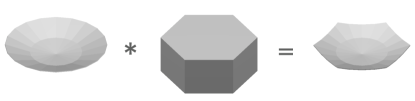
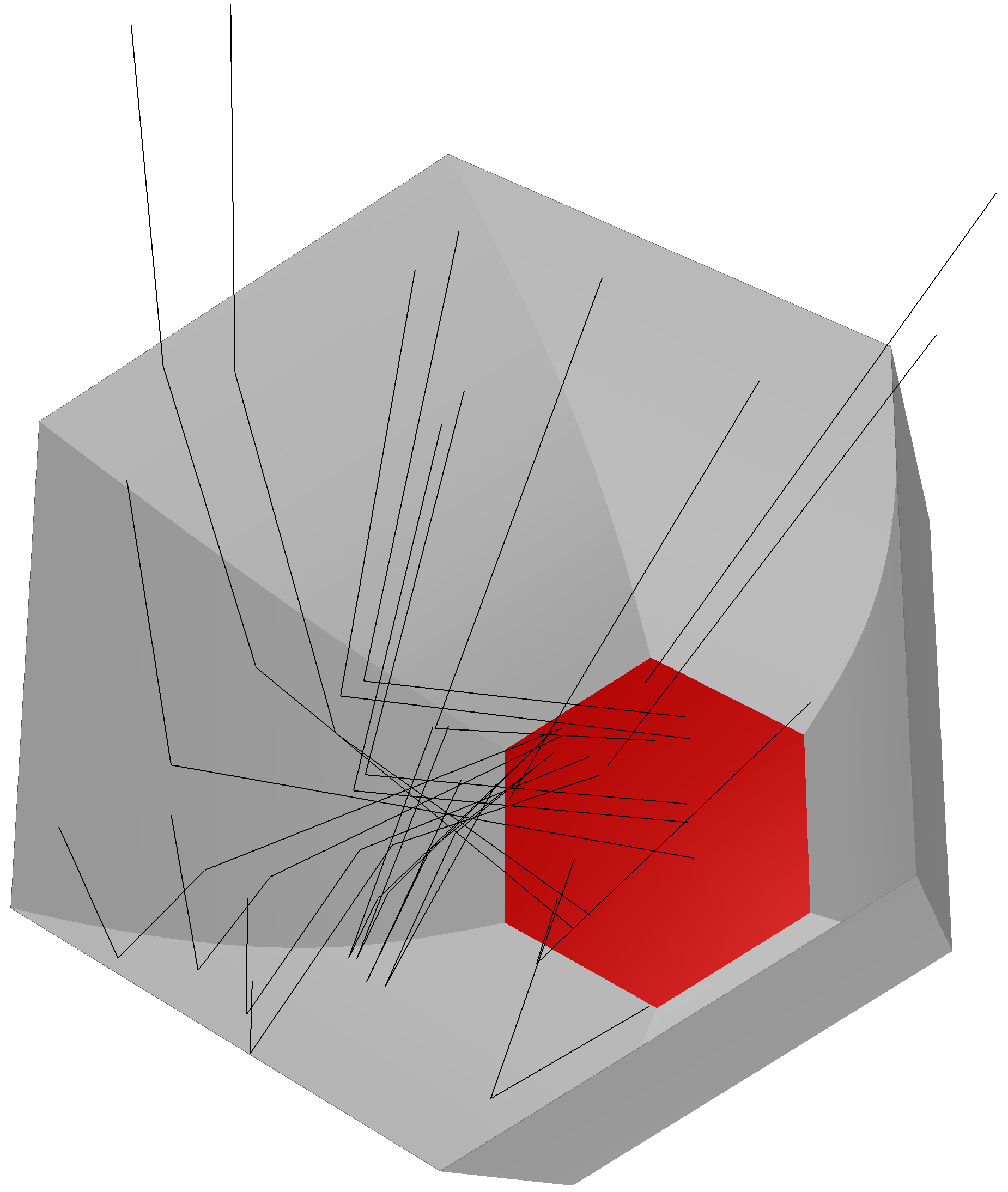
The core engine of ROBAST, libGeom, allows the user to build a variety of intricate geometries from more primitive shapes, such as spheres, rectangular boxes, cones, and tubes. Composite shapes can be created from primitive shapes using the Boolean operators union (+), subtraction (-), and intersection (*). A hexagonal spherical mirror created with ROBAST is illustrated in Figure 1.

Although many primitive-shape classes exist in libGeom, these shapes cannot create many important structures of CR telescopes, such as aspherical lenses and mirrors as well as compound parabolic concentrators [21, 22] (the latter are known as “Winston cones”). ROBAST can simulate light concentrators and optical systems with aspherical surfaces using additional shape classes (AGeoWinstonConePoly and AGeoAsphericDisk, respectively). Figure 2 illustrates a ROBAST simulation of a modified Baker–Nunn optical system comprising three aspherical lenses and segmented spherical mirrors. This complex example exhibits the advantage of ROBAST over other programs (the Zemax OpticStudio standard version, sim_telarray, and Geant4) that cannot simulate optical systems with segmented aspherical shapes or a hexagonal light concentrator in the non-sequential mode. A ROBAST application for a hexagonal light concentrator is given in subsection 3.5.
Importing 3D geometries from computer-aided design (CAD) software is sometimes required in simulations of composite telescope structures. While the Zemax OpticStudio professional version and Geant4 can import 3D geometry files (STL/IGES/STEP/SAT and geometry description markup language (GDML) [23], respectively), ROBAST is currently unable to import any external files, because libGeom does not fully support the GDML format and thus tessellated objects defined in the GDML format cannot be simulated. If libGeom fully supports GDML in the future, then ROBAST will be able to import 3D CAD geometries using GDML files.
2.2.4 Connectivity with Other Software
In simulations of CR telescopes with a ray-tracing program, air-shower simulators, electronics simulators, and data analysis software are often combined. Therefore, we provide ROBAST as a C++ library, enabling users to easily write their own software linked to other programs or libraries. To easily pipe Cherenkov photon data generated by CORSIKA [24] to the ray-tracing simulations, ROBAST also provides an interface class (ACorsikaIACTFile) that reads photon data files within ROBAST.
Another advantage of ROBAST is seamless connectivity with ROOT, which is extensively used in Monte Carlo simulations, data acquisition systems, and data analyses in CR experiments. Since ROBAST is written using ROOT libraries, ROBAST simulation results are easily analyzed in the ROOT framework. For example, spot diagrams (also referred to as geometrical point spread functions, PSFs) can be directly plotted using the 2D histogram classes provided in ROOT. By calling ROBAST classes from Python through PyROOT, users can combine ROBAST with other Python packages such as matplotlib.
2.2.5 Multi-platform Support
ROBAST is written in standard C++03 and requires only the ROOT libraries. It supports the two most used operating systems in the CR community, OS X and Linux777ROOT version 5 supports other POSIX and Windows systems. However, due to lack of requests from ROBAST users, ROBAST has not been tested on other platforms..
2.2.6 3D Visualization
Verifying the optics geometries is important in ray-tracing simulations. If a user’s program constructs an incorrect geometry of an optical system, the simulated PSFs will differ from the actual ones, and systematic errors can be generated from the estimated shadowing effect of the telescope masts, camera housing, and secondary mirror.
Without the visualization functionality, verification of ray-tracing simulators becomes more difficult. For instance, to visually check the accuracy of the given mirror geometries and shadowing, the user often draws the mirror shapes and shadows in 3D space by plotting the coordinates of a large number of photons that hit the segmented mirrors. In contrast, using the 3D visualization functionality provided with libGeom, users can more easily and more directly verify complex optical systems and their geometries visually. As shown in Figure 2, all the optical components and simulated rays can be drawn in an OpenGL888https://www.opengl.org view.
2.3 Classes
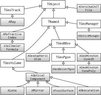
Although libGeom has excellent particle tracking and geometry construction functionality, it requires additional classes for ray-tracing simulations. ROBAST provides an optics simulation functionality, which is realized by the classes shown in Figure 3.
The TGeoManager class (inherited by AOpticsManager class in ROBAST) manages the particle tracking engine and geometry shapes in libGeom. AOpticsManager calculates the reflection, refraction, absorption, and photon scattering processes in user-defined optical systems through four distinct classes derived from AOpticalComponent: ALens, AMirror, AFocalSurface, and AObscuration.
-
1.
The ALens class
Any refractive medium can be modeled with the ALens class. In addition to normal optical lenses, ALens represents optical components with refractive indices or absorption lengths, such as the atmosphere, scintillators, and input windows of the photomultiplier tubes (PMTs). The user specifies the refractive indices using classes derived from ARefractiveIndex and can set the absorption lengths using the TGraph class of ROOT. Both these parameters are wavelength-dependent. -
2.
The AMirror class
The AMirror class models mirrors. The user specifies the mirror reflectance, which depends on the photon incidence angles and wavelengths. Light concentrators with specular surfaces are also modeled with this class. -
3.
The AFocalSurface class
Photodetectors at the focal planes are modeled with AFocalSurface. This class has a quantum efficiency (QE) property, which also depends on the photon incidence angles and wavelengths. -
4.
The AObscuration class
A body modeled with the AObscuration class absorbs all incident photons. AObscuration simulates the shadowing caused by telescope frames, masts, and camera housings.
The times, coordinates, and momenta of photons are contained in the ARay class. ARay also records all positions where a photon is reflected, refracted, or scattered.
Photon polarization is not yet supported in the current version of ROBAST (version v2.3p1 as of October 2015), and thus the user may need to pay special attention when his/her optical system could propagate photons with large incidence angles at optics boundaries. We have a plan to support photon polarization in a future version.
As mentioned in Section 2.2.3, complex geometries of CR telescopes require additional shape classes. Figure 1 shows how a simple composite geometry can be constructed from the primitive shapes implemented in libGeom. However, aspherical lenses, aspherical mirrors, or Winston cones cannot be constructed from such primitive shapes. Therefore, we have implemented AGeoAsphericDisk and AGeoWinstonConePoly classes in order to model these shapes in ROBAST. We have also implemented the AGeoBezierPgon class that simulates light concentrators composed of Bézier-curve walls (also referred to as Okumura cones) [25].
All the classes derived from AOpticalComponent, along with the shape classes provided by libGeom and ROBAST, should match the software requirements for the optical systems in most CR telescopes. If the user requires a new shape that is unavailable in libGeom or ROBAST, they can add new shapes by implementing a new class derived from TGeoBBox.
The imperfection of optical systems can be also taken into account in ROBAST simulations. For example, profile deviation from ideal mirror surfaces (“form deviation”) and the surface roughness of optics can be simulated (reflection and refraction angles are blurred) by using a boundary roughness property approximated by a 2D Gaussian. Misalignment of individual mirror facets and relocation of the camera position due to gravity can be mathematically described using the translation and rotation matrix classes in libGeom.
2.4 Cross-check with Other Programs
We verified the ROBAST classes and their ray-tracing calculations in comparisons with other independent programs, namely, sim_telarray (version 2015-07-21) and Zemax OpticStudio (version 13 release 2). As a cross-check, we here compare the spot diagrams of a Davies–Cotton telescope (H.E.S.S. I) simulated by sim_telarray and ROBAST, and those of a Schmidt–Cassegrain telescope by Zemax OpticStudio and ROBAST. Another comparison among these three programs for a CTA telescope is given elsewhere [26, 27].
Figure 4 shows the 3D ROBAST geometry of the Davies–Cotton optical system used in H.E.S.S. I telescopes. The 380 segmented spherical mirrors and the telescope structures (masts, trusses, camera housing, and camera lid) are modeled with the AMirror and AObscuration classes, respectively.
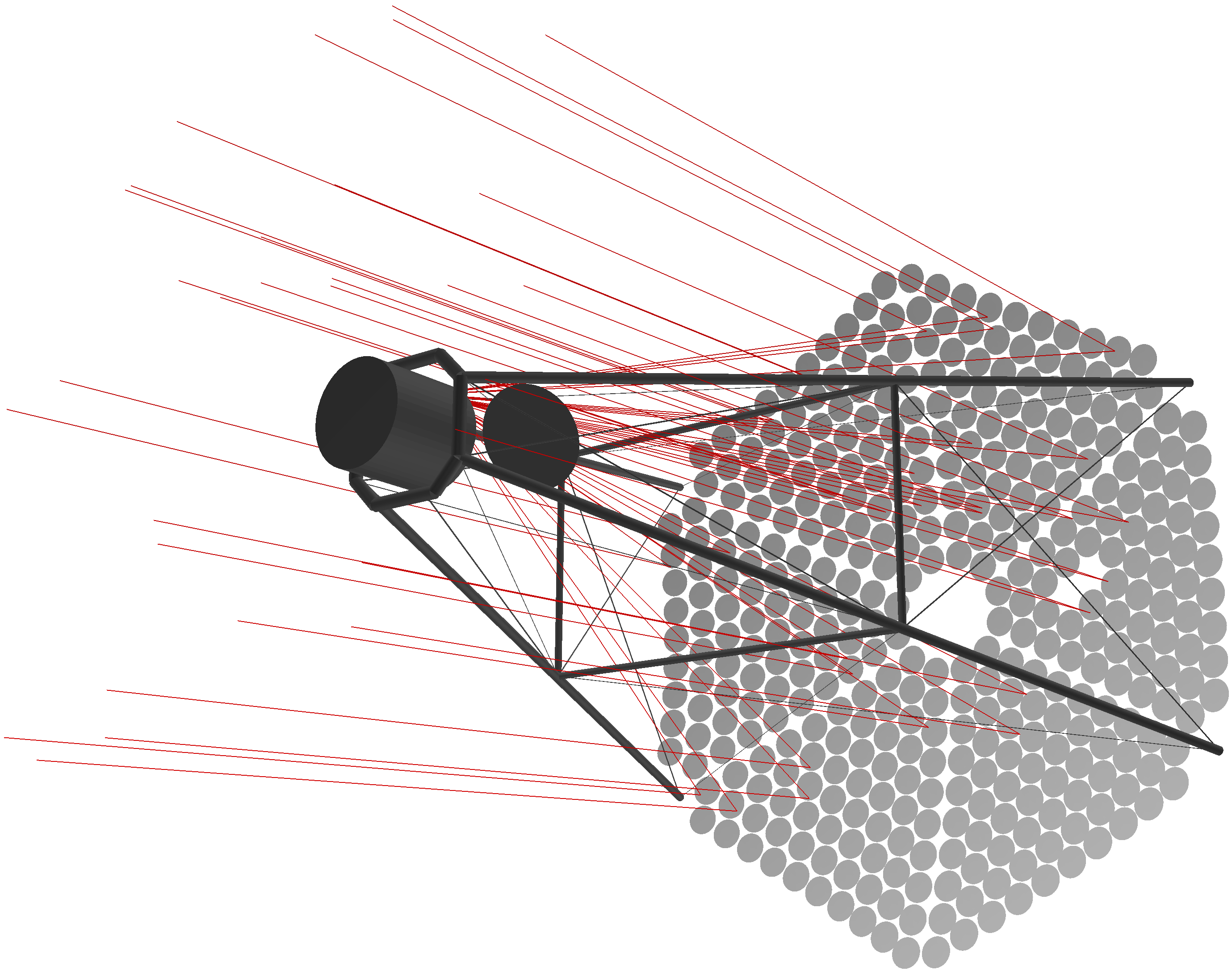
Figure 5 compares off-axis () spot diagrams of the H.E.S.S. I system calculated by sim_telarray and ROBAST, showing an excellent apparent agreement of the two programs. Small spot structures made by the spherical segmented mirrors are visible in the diagrams. One can also see shadowing effect by the telescope structure at around of and , for example. This verifies that rotation and translation matrices used for the alignment of the optics components and the ROBAST photon simulations with the AMirror and AObscuration classes work as expected.
Table 2 gives more quantitative comparison between the two programs. The standard deviations of simulated spot diagrams along and axes were calculated for various field angles, showing consistent values with each other, while very small deviations (%) up to times larger than the statistical fluctuations are seen.
| (deg) | (mm) | (mm) | ||
|---|---|---|---|---|
| sim_telarray | ROBAST | sim_telarray | ROBAST | |
| 0.0 | ||||
| 0.5 | ||||
| 1.0 | ||||
| 1.5 | ||||
| 2.0 | ||||
| 2.5 | ||||
Figure 6 shows the 3D ROBAST geometry of the Schmidt–Cassegrain telescope used for comparison between Zemax OpticStudio and ROBAST. The plano-aspheric lens, aspherical primary and secondary mirrors, and spider obscuration are modeled with the ALens, AMirror, and AObscuration classes, respectively. The geometries of the lens and mirrors are given in the AGeoAsphericDisk class.
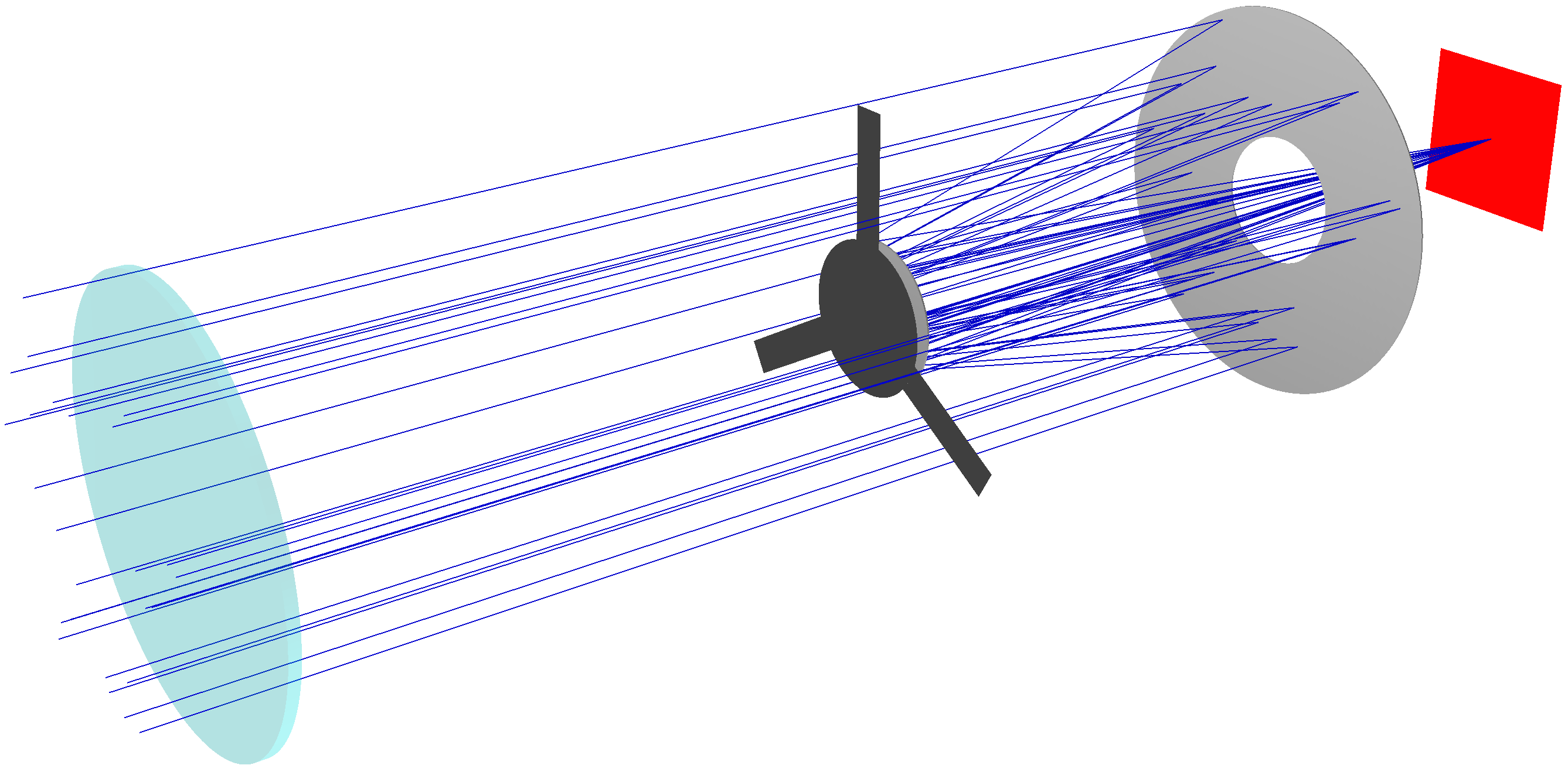
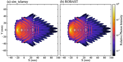
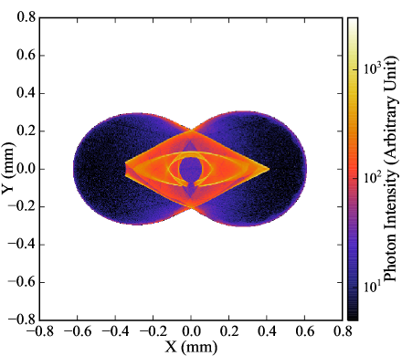
Figure 7 compares the off-axis spot diagrams simulated by Zemax OpticStudio and ROBAST. The field angle is and five different wavelengths are present together: nm, 530 nm, 587.6 nm, 610 nm, and 656.3 nm. The two diagrams are consistent, and both programs accurately reproduce the shadows cast by the spider arms, the different spot sizes of the five wavelengths, and the PSFs from the central peak position to the broad tail. This verifies that ALens, AMirror, AObscuration, and AGeoAsphericDisk yield the expected refractions, reflections, obscurations, and geometries, respectively.
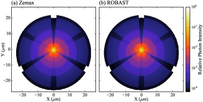
In the same way as the cross-check with sim_telarray, Table 3 compares the standard deviations of spot diagrams simulated by Zemax OpticStudio and ROBAST. The spot size difference between the two programs is less than % ( nm) and it is times smaller than the simulated wavelengths, whereas the difference is significantly larger than the statistical fluctuation. The systematic difference can be ignored in practical applications.
| (deg) | (m) | (m) | ||
|---|---|---|---|---|
| Zemax OpticStudio | ROBAST | Zemax OpticStudio | ROBAST | |
| 0.0 | ||||
| 0.1 | ||||
| 0.2 | ||||
| 0.3 | ||||
| 0.4 | ||||
| 0.5 | ||||
2.5 Functionality Comparison with Other Programs
As described in previous sections, ROBAST supports most of the functionality required for CR telescopes. However, other programs such as Zemax OpticStudio, sim_telarray, and Geant4 also play important roles in particular situations. Here, for the benefit of users, we compare the functionalities of ROBAST and these existing programs.
2.5.1 Zemax OpticStudio
Zemax OpticStudio is a commercial Windows application which has powerful functionalities for designs and studies of optics and illumination. Among its wide variety of functionalities, the optimization functionality of optics parameters (e.g., lens and mirror shapes) is the most important for CR telescope designs. ROBAST is also able to optimize optics parameters using optimization engines provided with ROOT, but the user needs to write C++ code for optimization, while Zemax OpticStudio offers an easy graphical user interface.
If one simulates an optical system whose imaging performance is affected by diffraction, it is recommended to use Zemax OpticStudio rather than ROBAST. However, this is not the case in most CR telescopes.
2.5.2 Geant4
Geant4 is widely used in simulations of particle physics experiments. It mainly simulates particle interactions and accompanying physics processes as well as tracking of high-energy particles and optical photons. It can also be used for CR telescope simulations as done in the fluorescence detectors of the Pierre Auger Observatory [2], but its built-in geometry shapes are limited (see Table 1 for comparisons). Furthermore, ROOT is more widely used in CR telescopes than Geant4, and thus ROBAST is easier to get started with and suitable for those who are already familiar with ROOT.
2.5.3 sim_telarray
sim_telarray has been developed to do full simulations of VHE gamma-ray events from telescope to electronics simulations, thus it is not a program dedicated only toward ray-tracing simulations. Users that need a full simulation suite for ground-based gamma-ray telescopes are encouraged to use sim_telarray.
Its ray-tracing simulation code is faster than ROBAST, because it uses the sequential method. However, the various optical designs that can be simulated with sim_telarray is limited. For example, optical systems with lenses or Winston cones cannot be handled in sim_telarray.
In practice, both ROBAST and sim_telarray are used in simulations of CTA. A good example is a shadowing factor parameter that is fed to a configuration file of sim_telarray. In the CTA simulation chain, shadows cast by telescope masts are not fully simulated in sim_telarray. Indeed the shadowing factors of two of the telescope designs proposed for CTA (SCT and GCT, see Sections 3.3 and 3.4) are dependent upon field angles. The shadowing factors for these telescopes are calculated in advance using ROBAST, and the results are written into sim_telarray configuration files.
3 Applications in the Cherenkov Telescope Array
3.1 The Cherenkov Telescope Array
The Cherenkov Telescope Array (CTA) is a next-generation ground-based gamma-ray observatory comprising two separate arrays of Cherenkov telescopes. These arrays will be constructed in the northern and southern hemispheres, enabling whole sky coverage. The CTA is designed to have a wide energy coverage ( GeV – TeV, and its gamma-ray detection sensitivity in the core energy band ( GeV – TeV) is expected to be greater by a factor of than that achievable by the current generation of gamma-ray telescopes [20, 28]: H.E.S.S.999http://www.mpi-hd.mpg.de/hfm/HESS/, MAGIC101010https://magic.mpp.mpg.de/, and VERITAS111111http://veritas.sao.arizona.edu/.
| Energy Coverage | Optics Design(s) | Diameter (m) | Focal Length (m) | FOV (deg) | |
| LSTs | – GeV | Parabola† | |||
| MSTs | GeV – TeV | Davies–Cotton (DC)‡ | |||
| SCTs | GeV – TeV | Schwarzschild–Couder (SC) | |||
| SSTs | – TeV | 2 SC and 1 DC | and | ||
| † The parabolic dish shape is approximated by spherical segmented mirrors. | |||||
| ‡ A variant mirror alignment compromises between the time spread and the off-axis PSF. | |||||
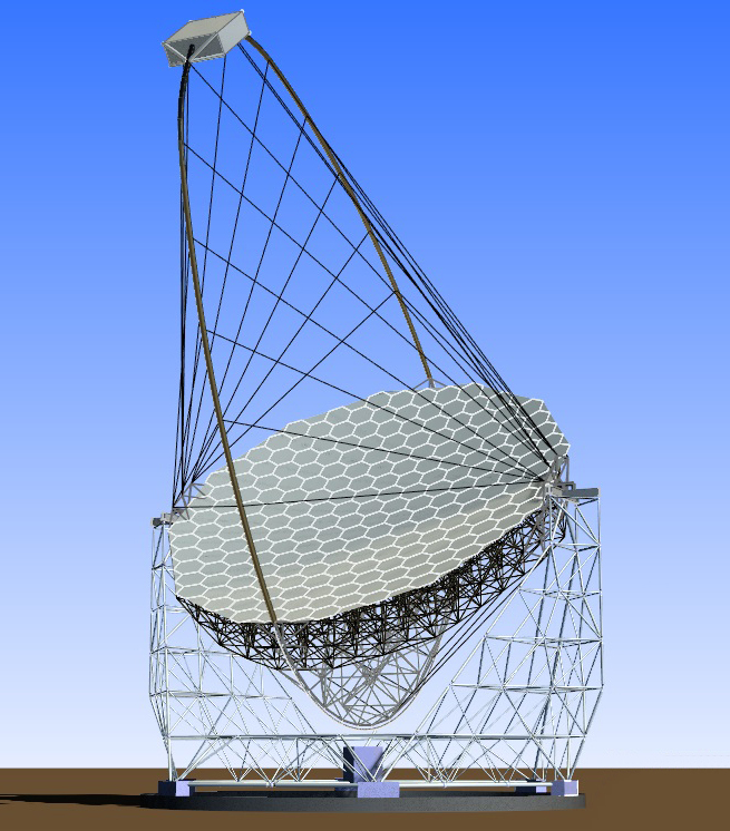
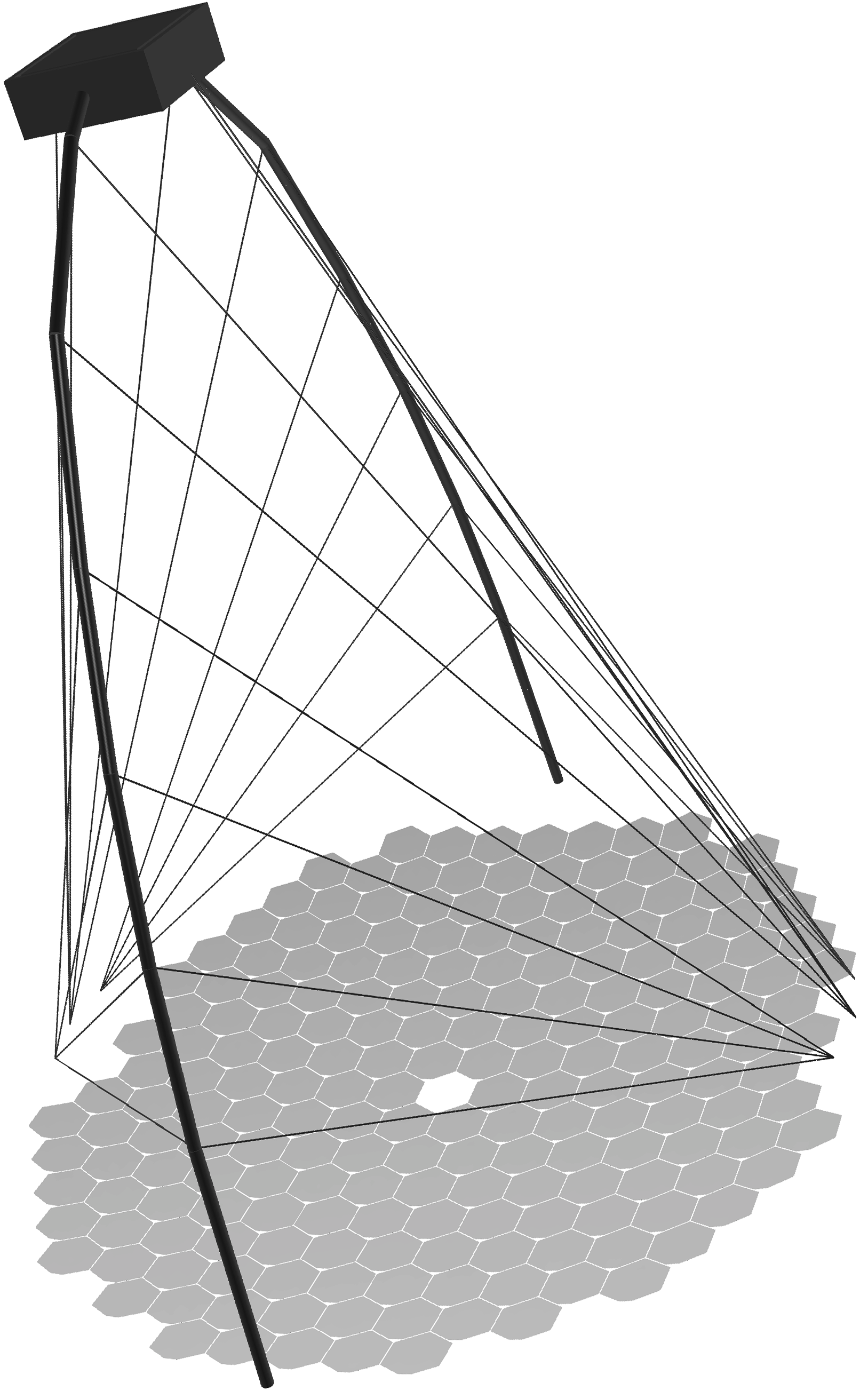
Several telescope designs that simultaneously achieve a wide effective area, high angular resolution, and wide energy coverage have been proposed and are listed in Table 4. Large-sized telescopes (LSTs) cover the lowest energy band (– GeV) with the largest-diameter mirror comprising segmented spherical mirrors aligned in a parabolic shape, as illustrated in Figure 8(a).
The middle energy band ( GeV – TeV) is mainly observed by medium-sized telescopes (MSTs). By virtue of a variant design of Davies–Cotton (DC) optics, MSTs realize a wider field-of-view (FOV) with more uniform angular resolution over the FOV than parabolic telescopes. To increase the effective area and improve the angular resolution of gamma-ray arrival directions in this energy band, Schwarzschild–Couder Telescopes (SCTs, also referred to as SC-MSTs) have been proposed as an extension of DC MSTs in the southern array. As their name indicates, SCTs are installed with an SC optics design comprising aspherical primary and secondary mirrors. Whereas the angular resolution of DC MSTs is -arcmin, that of an SCT is improved to arcmin. The mirrors in the SC design will be composed of 72 segmented mirror facets, as illustrated in Figure 8(b).
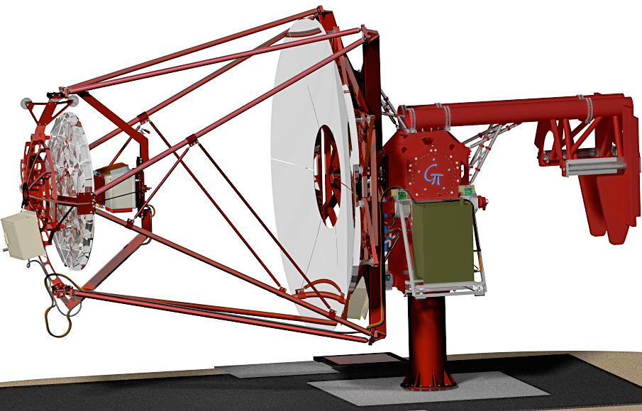
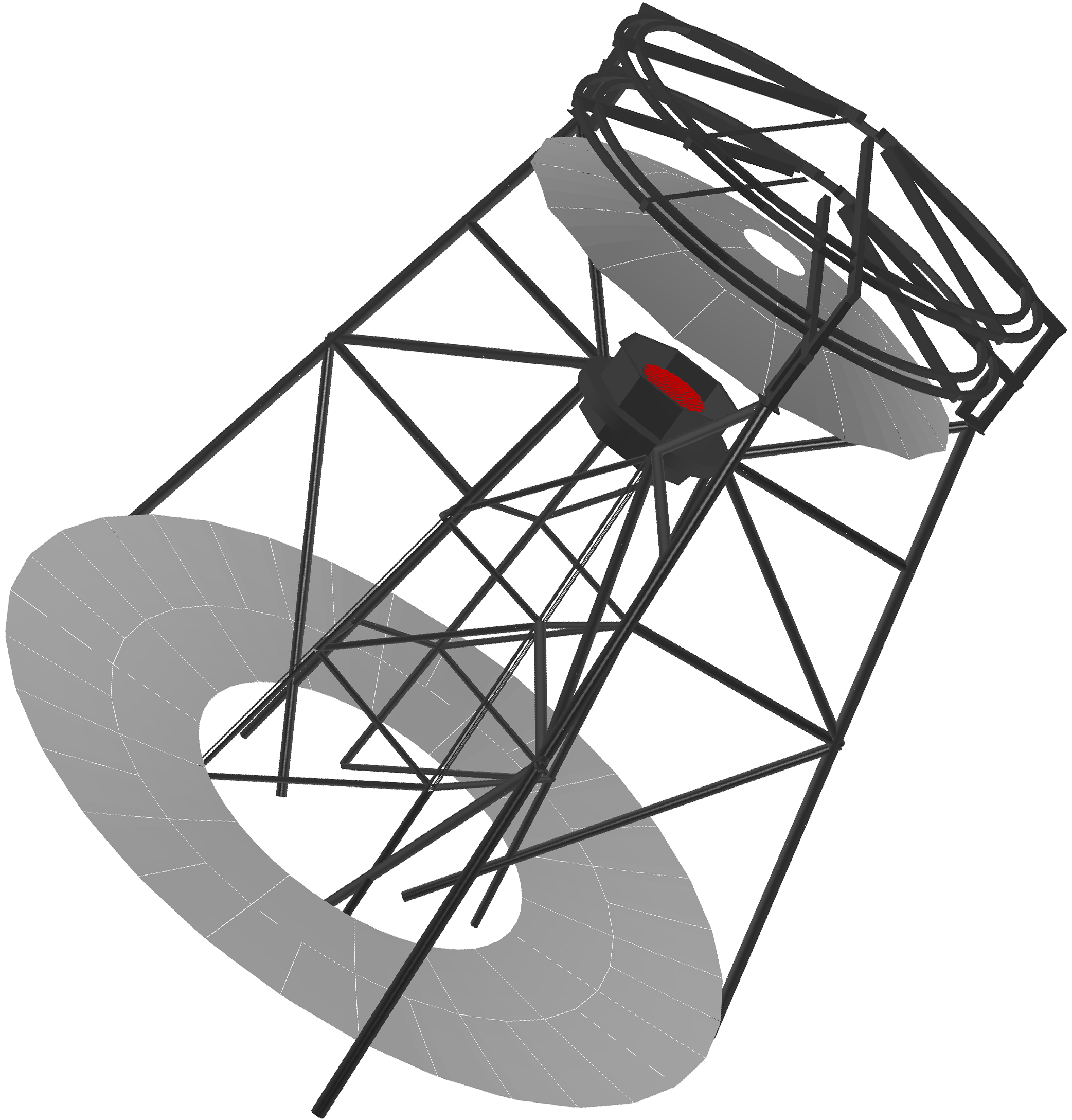
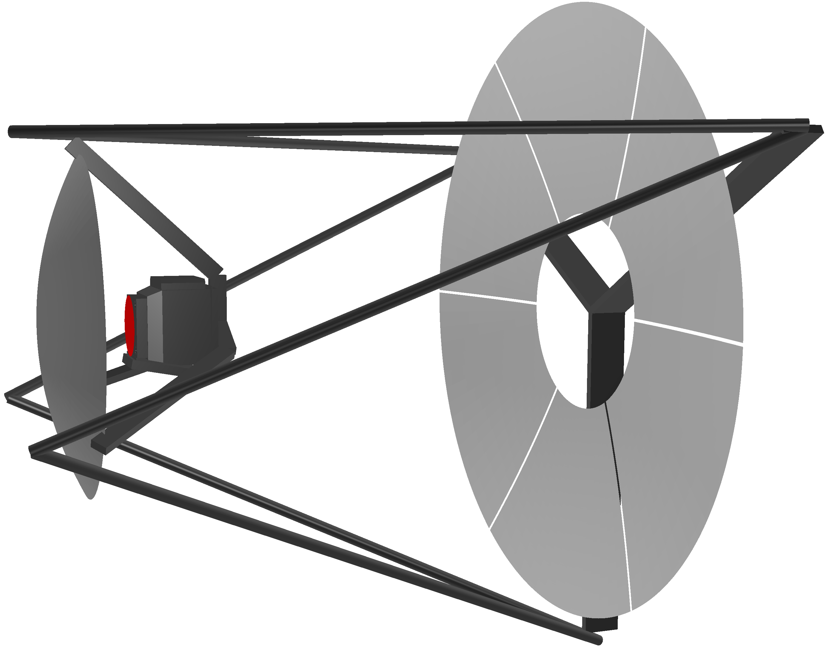
The highest energy band (– TeV) is covered by small-sized telescopes (SSTs). Three SST telescope designs (two SC and one DC) have been proposed. One of these is referred to as the Gamma Cherenkov Telescope (GCT; formerly SST-GATE) which also simultaneously achieves a wide FOV and high angular resolution using an SC optics system. Figure 8(c) shows a 3D CAD image of a GCT.
The northern array will constitute LSTs and MSTs. This array will mainly observe low-energy gamma rays from extragalactic objects such as active galactic nuclei and gamma-ray bursts. In contrast, the southern sky will be observed by LSTs, MSTs, and – SSTs (additional SCTs may be deployed), enabling a survey of the inner Galactic plane with higher sensitivity and a wider energy coverage (up to TeV) than is currently possible.
Among the six telescope designs, we used the ROBAST library for the LSTs, SCTs, and SSTs (GCTs). Using common software for the different CTA sub-projects, we substantially reduced the time and effort of software development in the large global collaboration. Moreover, the ROBAST functionality described in Section 2.2 is quite suitable for CTA telescopes comprising a large number of segmented mirrors and telescope frames. Such telescopes are important in image simulations, evaluation of shadowing, and tolerance analysis. Telescope array simulations with ROBAST are also integrated with other programs; e.g., GrOptics/CARE121212http://otte.gatech.edu/care/ adopts ROBAST as their ray-tracing engine. In the following subsections, we demonstrate the actual use of ROBAST in four CTA applications.
(a)
(b)
(c)
(d)
(e)
(f)
(g)
(h)
(i)
3.2 Large-Sized Telescopes
An LST has 198 segmented mirrors aligned on a parabolic surface. The whole surface diameter is m and the focal length is m [30]. Each mirror facet has a spherical surface with a radius of curvature of – m to approximate the parabolic dish. Its outer shape is a regular hexagon with a diameter of m (side to side), but one of its vertices is sliced off to make space for an alignment-monitoring CMOS camera. The shape of the mirror facet is non-trivial, but can be constructed from Boolean operations in libGeom (as explained in Figure 1). Figure 8(d) shows the LST geometry built with ROBAST. The segmented mirrors, camera housing, telescope masts, and 26 tension ropes are accurately reproduced.
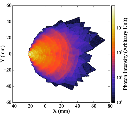
Figure 8(g) presents a ROBAST simulation of the LST optical system at a field angle of . Since the LST dish is nearly parabolic, comatic aberration caused by the outer segmented mirrors appears in the spot diagram. The diagram is vertically asymmetric, reflecting the asymmetry in the positions of the segmented mirrors. Many small structures introduced by the facet shape are also visible. Thin shadows cast by the tension ropes are visible on the outlying photons, verifying that the telescope structure built with the AObscuration class properly casts shadows on the mirrors.
As one might expect, Davies–Cotton optical systems are easily simulated by the same approach. Davies–Cotton system can be constructed from hexagonal segmented mirrors, and their arbitrary positions and directions can be given using libGeom.
3.3 Schwarzschild–Couder Telescopes
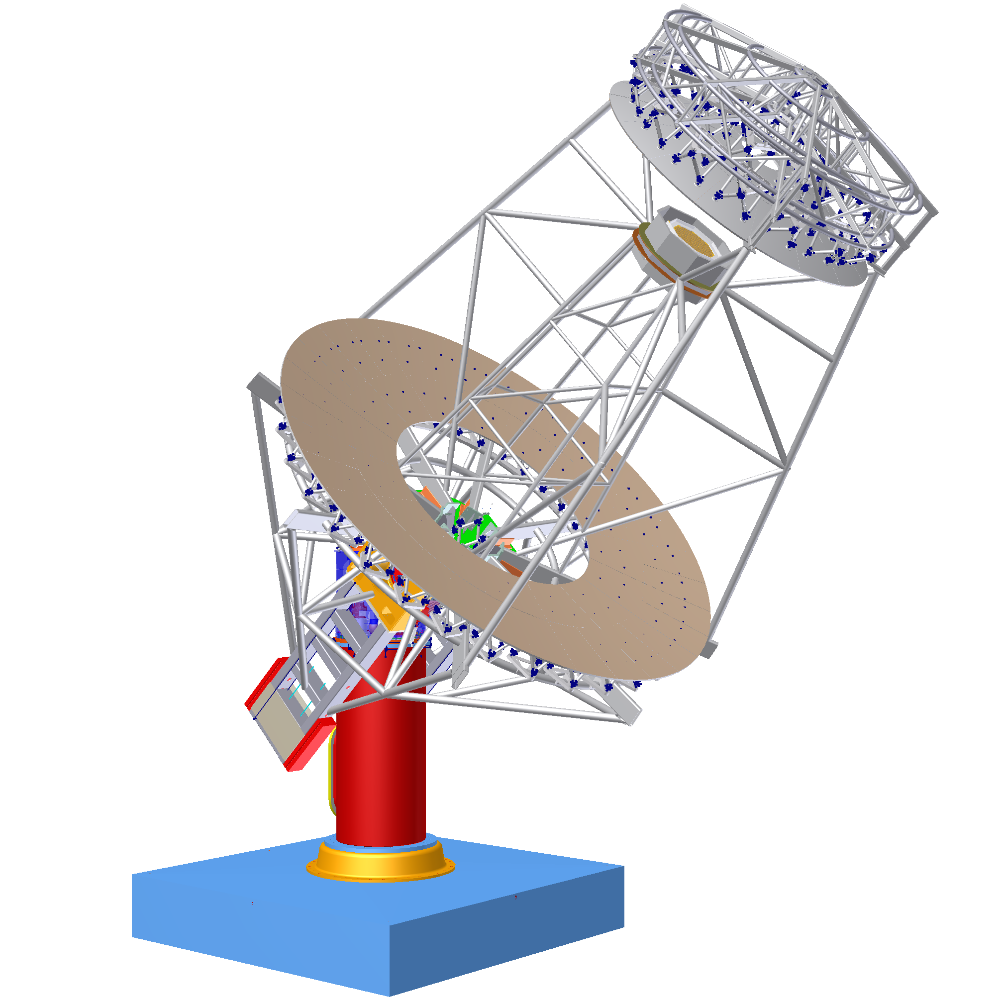
An SCT comprises aspherical primary and secondary mirrors, which suppress the aberrations appearing in wide FOV optical systems [19, 31, 32]. The angular resolution of the SCT is arcmin at field angles up to , which cannot be achieved by conventional parabolic or Davies–Cotton telescopes with a similar ratio. However, this optical system is built from a large number of aspherical segmented mirrors and includes a large-diameter ( m) secondary mirror with supporting structures (Figure 8(b)). Such a complex optical system with an accurate 3D geometry is difficult to simulate with Geant4 or other software using the sequential method.
Here, we successfully constructed the complex SCT geometry using ROBAST as shown in Figure 8(e). Tetragonal and pentagonal segmented mirrors with aspherical surfaces, the focal plane comprising camera modules ( image pixels), and the telescope frames were accurately reproduced.
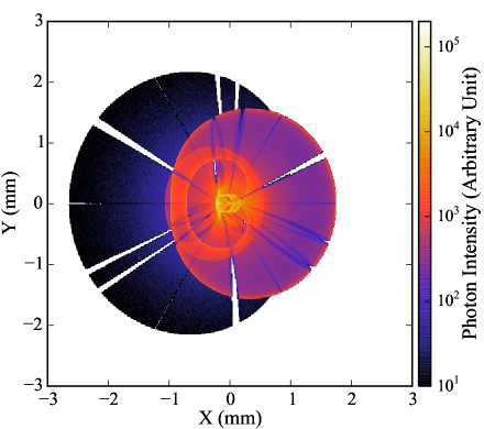
Figure 8(h) shows a spot diagram of the SCT optical system at a field angle of . The diagram is almost vertically symmetric, but asymmetric shadows cast by the telescope masts can been seen. Very thin shadows cast by small gaps between segmented mirrors are also visible.
3.4 Small-Sized Telescopes
The GCT optical system, one of the three SST design proposals [33, 11], is very similar to the SCT design, because it also employs an SC optical system. However, the primary mirror of a GCT comprises only 6 segmented mirrors, and the secondary is monolithic rather than segmented (see Figure 8(c)). The secondary mirror and camera housing in the GCT design are supported by tubular masts and rectangular trusses, respectively. These structures cast shadows on the mirror surfaces.
In GCT development, ROBAST was used to accurately calculate the GCT effective area and to evaluate the mirror misalignment tolerance [27]. Panels (f) and (i) of Figure 8 show ROBAST simulations of the GCT optical system and its off-axis PSF, respectively131313The ROBAST simulations were performed on an old telescope design that differs from Figure 8(c).. Shadows cast by the telescope masts are clearly visible in Figure 8(i).
3.5 Hexagonal Light Concentrators
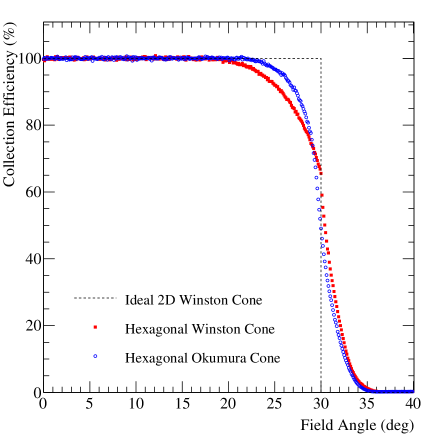
ROBAST has built-in classes that simulate the hexagonal light concentrators widely used in CR telescopes. This feature is a distinct advantage of ROBAST. A conventional hexagonal Winston cone, which is composed of six parabolic walls, can be easily simulated using the AGeoWinstonConePoly class141414Axisymmetric and other polygonal cones can be simulated as well.. A variant light concentrator composed of six Bézier-curve walls (an Okumura cone [25]) can also be simulated with the AGeoBezierPgon class as shown in Figure 9. This simulation reveals extensive non-sequential photon tracking by ROBAST; moreover, the multiple reflections on the cone surfaces are well-reproduced. Figure 10 compares the collection efficiencies of an ideal 2D Winston cone, a hexagonal Winston cone, and a hexagonal Okumura cone. These efficiencies were directly calculated and plotted with the TGraph class of ROOT.
Currently, a hexagonal light concentrator design proposed for the LST cameras is being developed using ROBAST. The cone shape was optimized in ROBAST simulations using the optimization scheme developed by Okumura [25]. To reproduce the light concentrator performance more accurately, the simulation accounted for the incidence angle and position dependence of the PMT photodetection efficiency, exploiting the functionality of the AFocalSurface class. Consequently, the final simulation result and measured collection efficiency of an LST light guide prototype significantly differs from that shown in Figure 10. In addition, using ROBAST simulations, the UV-enhanced coating of the cone was optimized in terms of the photon incidence angle distribution on its surface.
4 Conclusion
We have developed a new C++ library, ROBAST, which is intended for ray-tracing simulations of CR telescopes. To demonstrate the usefulness of ROBAST, we successfully simulated three telescope designs as well as a light concentrator proposed for CTA. Through these simulations we were able to confirm that the ROBAST functionalities meet the software requirements for accurate simulation of CR telescopes. In addition, we illustrated that ROBAST was able to simulate complex optical systems as accurately as independently produced programs such as Zemax OpticStudio, which are available commercially. The ROBAST library is freely available online and is expected to be used for the development of other CR telescopes as well as further simulations of CTA.
Acknowledgments
We are grateful to Dr. Andrei Gheata, the principal developer of the ROOT geometry library. We could not have developed ROBAST without his help and support. Dr. Akito Kusaka helped A. O. develop C++ code and initiated the idea of ray-tracing simulations. We also thank a number of colleagues in the Ashra collaboration and the CTA Consortium, who worked on the telescope optics designs and helped us simulate the ROBAST applications. We gratefully acknowledge Dr. Konrad Bernlöhr, who wrote sim_telarray and kindly allowed us to use part of his code in ROBAST. This study was supported by JSPS KAKENHI Grant Numbers 25610040 and 25707017. A. O. was supported by a Grant-in-Aid for JSPS Fellows.
References
- Tokuno et al. [2009] H. Tokuno et al., On site calibration for new fluorescence detectors of the Telescope Array experiment, Nucl. Instr. Meth. Phys. Res. A 601 (2009) 364 – 371.
- Abraham et al. [2010] J. Abraham et al., The fluorescence detector of the Pierre Auger Observatory, Nucl. Instr. Meth. Phys. Res. A 620 (2010) 227 – 251.
- Bernlöhr et al. [2003] K. Bernlöhr et al., The optical system of the H.E.S.S. imaging atmospheric Cherenkov telescopes. Part I: layout and components of the system, Astropart. Phys. 20 (2003) 111–128.
- Holder et al. [2006] J. Holder et al., The first VERITAS telescope, Astropart. Phys. 25 (2006) 391–401.
- Agostinelli et al. [2003] S. Agostinelli et al., Geant4–a simulation toolkit, Nucl. Instr. Meth. Phys. Res. A 506 (2003) 250–303.
- Bernlöhr [2008] K. Bernlöhr, Simulation of imaging atmospheric Cherenkov telescopes with CORSIKA and sim_telarray, Astropart. Phys. 30 (2008) 149 – 158.
- Daum et al. [1997] A. Daum et al., First results on the performance of the hegra iact array, Astroparticle Physics 8 (1997) 1–11.
- Bernlöhr et al. [2013] K. Bernlöhr et al., Monte carlo design studies for the Cherenkov Telescope Array, Astroparticle Physics 43 (2013) 171–188.
- Sasaki et al. [2002] M. Sasaki, A. Kusaka, Y. Asaoka, Design of UHECR telescope with 1 arcmin resolution and 50∘ field of view, Nucl. Instr. Meth. Phys. Res. A 492 (2002) 49–56.
- Lopez [2013] M. Lopez, Simulations of the MAGIC telescopes with matelsim, in: Proc. 33rd Int. Cosmic Ray Conf., 2013.
- Zech et al. [2013] A. Zech et al., SST-GATE: A dual mirror telescope for the Cherenkov Telescope Array, in: Proc. 33rd Int. Cosmic Ray Conf., 2013.
- Aguilar et al. [2015] J. Aguilar et al., Design, optimization and characterization of the light concentrators of the single-mirror small size telescopes of the cherenkov telescope array, Astroparticle Physics 60 (2015) 32 – 40.
- Brun and Rademakers [1997] R. Brun, F. Rademakers, ROOT – an object oriented data analysis framework, Nucl. Instr. Meth. Phys. Res. A 389 (1997) 81 – 86. New Computing Techniques in Physics Research V.
- Brun et al. [2003] R. Brun, A. Gheata, M. Gheata, The ROOT geometry package, Nucl. Instr. Meth. Phys. Res. A 502 (2003) 676–680.
- Aita et al. [2008] Y. Aita et al., Ashra Mauna Loa Observatory and slow control system, in: L. Nellen, F. A. Sánchez, J. F. Valdés-Galicia (Eds.), Proc. 30th Int. Cosmic Ray Conf., volume 3, 2008, pp. 1405–1408.
- Marchi et al. [2010] A. Z. Marchi, Y. Takizawa, R. Young, Y. Takahashi, The JEM-EUSO mission and its challenging optics system, in: International Conference on Space Optics, 2010.
- Anderhub et al. [2013] H. Anderhub et al., Design and operation of FACT – the first G-APD Cherenkov telescope, Journal of Instrumentation 8 (2013) P06008.
- Davies and Cotton [1957] J. M. Davies, E. S. Cotton, Design of the quartermaster solar furnace, The Journal of Solar Energy Science and Engineering 1 (1957) 16–22.
- Vassiliev et al. [2007] V. Vassiliev, S. Fegan, P. Brousseau, Wide field aplanatic two-mirror telescopes for ground-based -ray astronomy, Astropart. Phys. 28 (2007) 10–27.
- Actis et al. [2011] M. Actis et al., Design concepts for the Cherenkov Telescope Array CTA: an advanced facility for ground-based high-energy gamma-ray astronomy, Experimental Astronomy 32 (2011) 193–316.
- Winston [1970] R. Winston, Light collection within the framework of geometrical optics, Journal of the Optical Society of America 60 (1970) 245–247.
- Punch [1994] M. Punch, Winston cones for light-collection and albedo protection in CAT, in: T. Kifune (Ed.), Towards a Major Atmospheric Cerenkov Detector III, Universal Academy Press Inc., Tokyo, 1994, pp. 215–220.
- Chytracek et al. [2006] R. Chytracek, J. McCormick, W. Pokorski, G. Santin, Geometry description markup language for physics simulation and analysis applications, Nuclear Science, IEEE Transactions on 53 (2006) 2892 –2896.
- Heck et al. [1998] D. Heck, J. Knapp, J. N. Capdevielle, G. Schatz, T. Thouw, CORSIKA: A Monte Carlo Code to Simulate Extensive Air Showers, 1998.
- Okumura [2012] A. Okumura, Optimization of the collection efficiency of a hexagonal light collector using quadratic and cubic Bézier curves, Astropart. Phys. 38 (2012) 18–24.
- Armstrong et al. [2015] T. Armstrong, H. Costantini, C. Rulten, V. Stamatescu, A. Zech, Monte Carlo Studies of the GCT Telescope for the Cherenkov Telescope Array, in: Proc. 34th Int. Cosmic Ray Conf., 2015.
- Rulten [2015] C. Rulten, A. Zech, A. Okumura, P. Laporte, J. Schmoll, Simulating the optical performance of a small-sized telescope with secondary optics for the Cherenkov Telescope Array, in preparation (2016).
- Acharya et al. [2013] B. S. Acharya et al., Introducing the CTA concept, Astropart. Phys. 43 (2013) 3–18.
- Okumura et al. [2015] A. Okumura, K. Noda, C. Rulten, ROBAST: Development of a non-sequential ray-tracing simulation library and its applications in the Cherenkov Telescope Array, in: Proc. 34th Int. Cosmic Ray Conf., 2015.
- Ambrosi et al. [2013] G. Ambrosi et al., The Cherenkov Telescope Array Large Size Telescope, in: Proc. 33rd Int. Cosmic Ray Conf., 2013.
- Rousselle et al. [2013] J. Rousselle et al., Schwarzschild-Couder telescope for the Cherenkov Telescope Array: Development of the optical system, in: Proc. 33rd Int. Cosmic Ray Conf., 2013.
- Vassiliev et al. [2013] V. Vassiliev et al., Schwarzschild-Couder telescope for the Cherenkov Telescope Array: 9.5m telescope prototype development, in: Proc. 33rd Int. Cosmic Ray Conf., 2013.
- Laporte et al. [2012] P. Laporte et al., SST-GATE: an innovative telescope for very high energy astronomy, in: Proc. SPIE, volume 8444, 2012, pp. 84443A–84443A–15. doi:10.1117/12.966860.