Web application for size and topology optimization of trusses and gusset plates
Abstract
With its ever growing popularity, providing Internet based applications tuned towards practical applications is on the rise. Advantages such as no external plugins and additional software, ease of use, updating and maintenance have increased the popularity of web applications. In this work, a web-based application has been developed which can perform size optimization of truss structure as a whole as well as topology optimization of individual gusset plate of each joint based on specified joint displacements and load conditions. This application is developed using cutting-edge web technologies such as Three.js and HTML5. The client side boasts of an intuitive interface which in addition to its modeling capabilities also recommends configurations based on user input, provides analysis options and finally displays the results. The server side, using a combination of Scilab and DAKOTA, computes solution and also provides the user with comparisons of the optimal design with that conforming to Indian Standard (IS 800-2007). It is a freely available one-stop web-based application to perform optimal and/or code based design of trusses.
keywords:
Topology Optimization, Truss Design, Web Application, Size Optimization, SaaS1 Introduction
Cloud computing has gained tremendous popularity in recent years with a large number of applications being designed as Software as a Service (SaaS). SaaS entails applications that are delivered over the web to end users while core computations take place on remote server(s). The key advantage of such applications is that they enable users to perform computationally intensive tasks using personal machines of modest configurations. In fact, many of these applications can even be executed on hand held devices. The ongoing cloud revolution has also shown its footprints in optimization and structural analysis in the form of web-based tools that have been developed in the past few years. Eynard et al. [1] discussed various benefits obtained by deploying web based technologies in the fields of mechanical design and structural analysis.
Optimal design of structures is often the holy grail of engineers and designers. A combination of structural (finite element) analysis software, such as ANSYS [2] and optimization packages, such as DAKOTA [3] is typically employed to achieve optimal designs. Several commercial finite element packages have recently began providing in-built optimization modules which can be utilized with analysis routines in a coupled manner. While such commercial packages are popular among structural designers, the need for open source and easy to use software cannot be undermined.
SaaS oriented optimization and structural analysis web applications provide an attractive alternative to equivalent commercial software packages. In the context of the present study, such applications can be divided into two broad categories: one concerning structural analysis and other dealing with optimization. The similarity among the two categories lies in their client-server model wherein core computations take place at a centralized location (server) while the so-called front end is provided over the Internet through various web-based technologies such as HTML, Javascript, PHP, SQL and DQL, etc.
Peng and Law [4] developed a prototype framework for Internet oriented collaborative development of a structural analysis program. They employed OpenSeeS [5], a freely available nonlinear finite element package, at the back-end to demonstrate their framework and a typical web-based interface for user interaction. However, input files for the model were required to be provided in Tool Command Language (Tcl) [6], a scripting language understood by OpenSees with no graphical input capabilities. They did provide a user interface based on Matlab [7] using which the users can download analysis data that can be directly visualized in Matlab.
Later, Yang et al. [8] developed a web-based platform for computer
simulation of seismic ground response. Their application employed Cyclic1D [9], a nonlinear finite element simulation platform for computing
nonlinear seismic ground response of soils. More recently, Gracia and Bayo [10] developed an integrated 3D web application for
structural analysis. The work of Gracia and Bayo marked a paradigm shift in the
use of latest web technologies for the purpose of structural analysis. While
earlier efforts required the user to have some level of familiarity with the
underlying computational engine (to be able to write appropriate input files),
Gracia and Bayo alleviated this requirement by providing WebGL-based
[11] interface that allows users to graphically manipulate the
structural model. The core structural analysis module was written in C++ and was
linked to the web interface through PHP. Hejazi et al. [12]
developed an interactive finite element web application for linear and nonlinear
analysis of reinforced concrete structures subjected to static and dynamic
loading. An exception to the web-based
structural engineering software developed prior to the year 2013 is the one
developed by Chen et al. [13] which featured a rich Java-based
graphics user interface (GUI) on the client side and a parallel C++-based finite
element module on the server side.
A web-based post processing tool for finite element analysis was developed by Weng [14]. This tool functioned by maintaining a database of all the finite element input and analysis data, and provided an improved graphical environment to visualize and post process this data. Internet-based grid computing environments for structural analysis have also been developed. Since grid computing is not in the scope of the present work, it will not be touched upon in detail. Interested readers may refer to the literature [15, 16, 17, 18] for more details.
From the optimization standpoint, the studies covered herein involve web based topology optimization tools. Tcherniak and Sigmund [19] developed the first web-based topology optimization tool [20] which is, perhaps, the most popular online topology optimization tool. Paulino et al. [21] developed a Java-based topology optimization program with web access while more recently, Nobel-Jørgensen et al. [22] developed a 3D topology optimization tool for hand held devices and demonstrated its usability on iPad.
Evidently, the available web-based tools for structural analysis and topology optimization exist in isolation. The present study is the first attempt in providing a combined application. Moreover, the present application is not limited just to topology optimization and includes capabilities of DAKOTA [3] to perform weight and size optimization as well. Key capabilities of the developed web application include structural analysis of trusses using matrix method, analysis of plates using finite element method, design of trusses as per the IS 800:2007 [23] (the Indian code of practice for design of steel structures), optimal design of trusses, and topology-optimized design of gusset plates. It is expected that this web application will be useful for structural engineers and designers as well as students and educators. Owing to its simplistic and intuitive design, it can be easily utilized to perform any of the aforementioned tasks and more broadly, can be viewed as a one-stop solution to 2D truss analysis and design problems. While space trusses are not yet supported, this capability will be added in the future. Nevertheless, in many applications, roofs are constructed using a series of 2D trusses. Such cases can be handled by the application and hence, it can be utilized for design of supporting trusses of roofs.
We first describe the various aspects of web application and the analysis capabilities of the web application. Then we answer the question of verification (“Are we solving the problem right”) by comparing the results of the web application with analytical solution and finally demonstrate how the web application can be used to solve typical engineering problems.
2 Development of Web Application
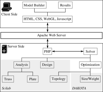
The web application is hosted on an Apache web server and comprises of several client and server side components, as detailed in Figure 1. The client side components primarily include a WebGL-based graphical model builder and a dynamic page that displays analysis results. Server side components include analysis, design and optimization solvers developed in Scilab [24] and DAKOTA [3]. PHP is employed to manage the flow of data (input/output of parameters and results to/from the solver). Thus, the user only requires a web browser with a working Internet connection to use the web application as all the computationally intensive tasks are carried out on the server side.
2.1 Input Interface
The input interface has been designed using latest web technologies such as Three.js, HTML5, CSS and Javascript and is shown in Figure 2. The input interface comprises of eight main components demarcated by blocks through in Figure 2. Block is a set of buttons that provides all the action items of the application. Block is the drawing canvas made using Three.js (an extension of WebGL) that allows the users to construct geometries of the problems they wish to analyze.
Nodes can be specified by right-clicking the mouse within the canvas. By default, nodes are placed at grid points and the node table in block is automatically populated with newly added nodes. Finer adjustments of node positions can be made by altering the ‘X’ and ‘Y’ coordinate values in block . Block can also be utilized to prescribe nodal loads and nodal support conditions. User can specify dead load (DL), live load (LL) and wind load (WL) and any number of their combinations. A combination can be added by specifying corresponding factors for dead load, live load and wind load as shown in Block . Load combination suggested by the web application are 1.5(DL + LL), 1.2(DL + LL + WL) and 1.5WL + 0.9DL. Presently, three types of support conditions, sufficient to describe trusses, can be specified: roller, hinged, and free; by default, every node is free. Deletion of nodes, if required, can be performed using the ‘Delete’ option provided against respective nodes.
Members or elements can be added by left-clicking on the starting node and dragging the mouse to the ending node. The member table in block is automatically populated with the newly formed members. Just like nodes, members can be deleted by using the ‘Delete’ link provided against respective members. An additional feature ‘Split’ is provided that can be used to introduce an additional node at the mid-point of the member.
Blocks and are dynamic tables where users can add materials and cross-sectional properties to be used in the structural model. Poisson ratio, , Young’s modulus, , yield stress, , and ultimate stress, , are required to be specified for each material. By default, block contains properties corresponding to steel. As for cross-sectional properties, the area of cross section is required to be provided; the default value for which is . All the newly created members are assigned default values for material and cross-section which can be changed in block .
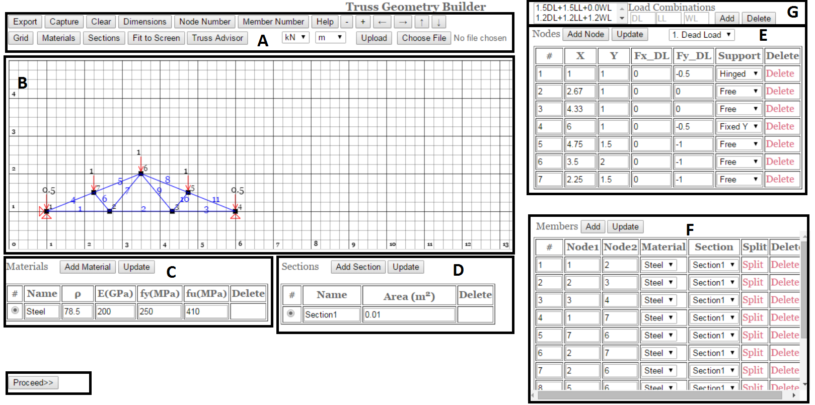
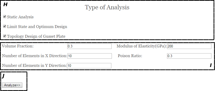
Once all the inputs have been specified, user clicks on the ‘Proceed’ button provided in block that takes the user to the next input page in which the types of analyses/design to be carried out can be specified. The second input page is shown in Figure 3. Block shows the types of analyses supported by the web application. The user can select one or more of the analysis/design options. Block shows parameters relevant to the gusset plates and topology optimization. The input ‘Volume Fraction’ is specified for carrying out the topology optimization of gusset plates. Number of elements in X and Y directions are utilized to specify the size of the finite element mesh to be employed for analysis of plates. Finally, when all the inputs have been specified, the ‘Analyze’ option in block can be utilized to begin the analysis. Once this button is clicked, all the model data is sent to the server where the analysis is carried out.
While the input interface has been described with respect to building a truss model, the interface is similar for modeling of plates. Users get access to some additional features, such as choosing the type of 2D idealization (plane stress or plane strain) and specification of thickness in case of plates. Full details are not provided for the sake of brevity.
2.2 User Friendly Features
Several user friendly features are provided through the buttons provided in block . It is recognized that users may wish to save their work and/or reuse previously generated models. The ‘Export’ option allows users to save the entire model as a csv file that can be utilized to work with the saved model at a later time through the ‘Choose File’, ‘Upload’ and ‘Show’ options. The ‘Capture’ option allows users to save a screen-shot of the present view of the model while ‘Dimensions’, ‘Node Number’, ‘Member Number’, ‘Grid’, ‘Show Materials’, and ‘Show Sections’ are toggle options provided to enable showing/hiding of relevant visual features. When the ‘Show Materials’ or the ‘Show Sections’ options are switched on, the members are color coded with respective materials and/or sections. Further, it is possible to zoom and pan the canvas using the ‘+’, ‘-’, ‘’, ‘’, ‘’, and ‘’ options. The option of ‘Fit to Screen’ is also provided to facilitate zooming.
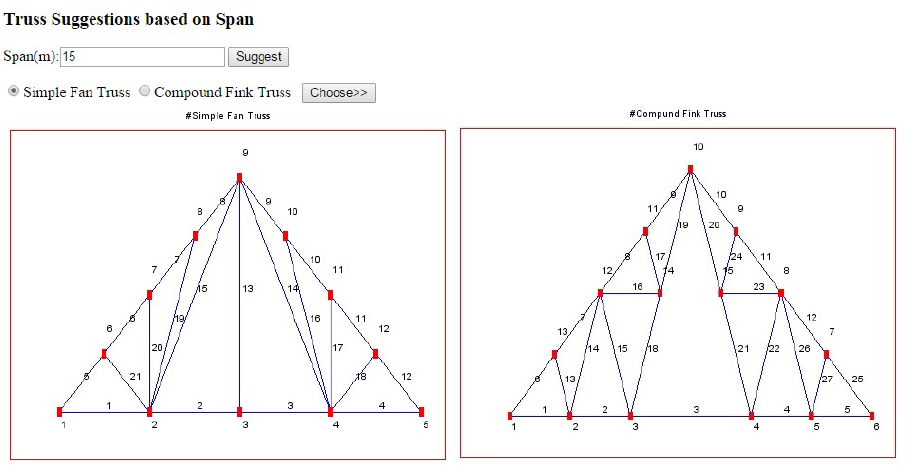
In order to make the web application more accessible for persons with limited knowledge of truss systems, a ‘Truss Advisor’ option is provided. Once utilized, it leads the user to a help page, shown in Figure 4. In this page, the user can specify the total span to be covered by the truss and the web application shows relevant suggestions. If the user chooses a suggestion from this page, it automatically gets loaded in the main input section. It is possible to customize the pre-loaded truss system by making use of tables through on the main input page.
2.3 Core Computational Routines
The core computational routines correspond to the types of analyses the web application is capable of performing. First of these is static analysis of trusses. A matrix analysis based method has been implemented in Scilab to carry out analysis of trusses subjected to static loads. Through this analysis, the forces in all members and deflections at all nodes are computed.
Next is limit state design of trusses as per the code of practice for steel structures published by Bureau of Indian Standards (BIS), IS 800:2007 [23]. The design algorithm has been implemented in Scilab and comprises of a library of standard angle sections provide in IS 800:2007. The peripheral members of the truss are designed as using double angle sections while the interior ones are designed as single angle sections. Connections of members and gusset plates are assumed to be fillet weld connections in accordance with IS 800:2007. All the checks prescribed by IS 800:2007 for tension and compression members are enforced by the design algorithm. Zero force members are assigned section of minimum weight from the library.
In addition to analysis and limit state design of trusses, the web application can also address weight/size optimized design of trusses. A combination of Scilab routines and DAKOTA is utilized to achieve this. DAKOTA offers a wide range of gradient-based and non-gradient-based optimization algorithms. In the optimization problem, minimization of the weight of the truss is posed as the objective function. Member stresses are constrained to remain within the elastic limit of the material and the slenderness ratios of the members are constrained to remain within the limits prescribed by IS 800:2007. The conmin_mfd optimizer of DAKOTA is being utilized which is a constrained minimization algorithm [25].
To consummate the optimal design of the truss assembly a complete specification of gusset plates is required. In order to achieve optimal gusset plate designs, a topology optimization routine implemented in Scilab is utilized. All the gusset plates of the structural model are initially assumed to be rectangular and the member forces are distributed equally within the welded portion (actual connection of gusset plate and truss member). The weight/volume of the gusset is optimized following the same algorithm proposed by Sigmund [26]. Current implementation does not include addition of stress/displacement constraints. It is assumed that the axis of all the members connected to a gusset plate intersect at the centroid of the plate and the members do not overlap, i.e., adjacent members sharing a gusset plate only touch each other at the vertices. With this assumption and given orientation of each member identifying the position of each member in a gusset plate is a trivial task.
The member forces are transferred to the gusset plate in two steps. First, all the nodes of the FE model of the plate that lie within on the weld region are identified and then, the member forces are applied to these nodes with equal distribution. From a numerical, essential boundary conditions also need to be specified to ensure a unique displacement field. Minimal boundary conditions are chosen to eliminate rigid body modes thereby not influencing the solution significantly. The centroid is fixed to prevent translations and horizontal translation for a node below the centroid location is also prevented to eliminate rigid body rotations.
The initial density of the material is assumed to be constant for all elements of the FE model of the gusset plate. The solid isotropic material with penalization (SIMP) approach [27], which utilizes a penalizing factor to ensure continuous design variables are enforced towards black and white design, is employed to achieve topology optimized shapes of the gusset plates.
2.4 Output Interface
The results are displayed on the client side in the form of tables, downloadable text files, and images. Forces in each member, design summary as per IS 800:2007 and the optimization results from DAKOTA are displayed in a tabular format wherein they can be readily compared. Furthermore, detailed design results with a comprehensive step-by-step summary are available for download by the user in txt format. Topology optimization results are displayed as JPEG images which can also be downloaded by the user. More details of the output interface are discussed in later sections.
3 Verification Studies
In applications related to science and engineering there is always a need for evaluating the reliability of the computer model. Rigorous standards have been developed in the field of fluids and solid mechanics to answer the question of “Verification and Validation”. Verification deals with showing that the developed numerical model shows good convergence and has error bounds on quantities of interest and validation deals with the correlation between the model results and what is really observed. Since standard matrix analysis, finite element analysis for plane stress/plane strain and topology optimization have been validated by researchers we focus over attention to verification of the web application. We consider three cases which serve as a means of verification for (a) matrix analysis module for solving truss assembly, (b) finite element module for plane stress/strain analysis, and (c) topology optimization module.
3.1 Matrix analysis module
A simple symmetric truss assembly shown in Figure 5(a) was chosen as the verification problem. The span was taken to be m and the height was taken as m. Loads applied to this assembly were also chosen to be symmetric. The deformed shape of the truss assembly as computed by the web application is shown in Figure 5(b) (presently, the deformed shape is not reported in the web application. This plot was generated for the purpose of verification). The deformed shape shows a symmetric profile which is expected from the inherent symmetry in the problem. The individual member force values computed by the web application show good agreement with the analytical solution (paper and pen) (Table 1).
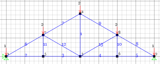
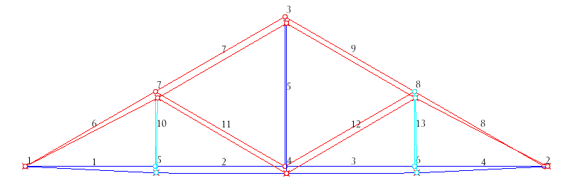
| Member | 1 | 2 | 3 | 4 | 5 | 6 | 7 | 8 | 9 | 10 | 11 | 12 | 13 | |
|---|---|---|---|---|---|---|---|---|---|---|---|---|---|---|
| Forces (kN) | Web App | -5.19 | -5.19 | -5.19 | -5.19 | -2 | 5.99 | 3.99 | 5.99 | 3.99 | 0 | 1.99 | 1.99 | 0 |
| Analytical | -5.2 | -5.2 | -5.2 | -5.2 | -2 | 6 | 4 | 6 | 4 | 0 | 2 | 2 | 0 | |
| Error | -0.19% | -0.19% | -0.19% | -0.19% | -0.00% | -0.17% | -0.25% | -0.17% | -0.25% | -0.00% | -0.50% | -0.50% | -0.00% |
3.2 Finite element module
A cantilever beam of length m, thickness m and depth m was solved with a point load of kN applied at the end. The mesh was refined and the tip displacement was compared against analytical solution as shown in figure 6. If is the number of elements through the depth, then elements were set along the length. In the finest mesh (1690 elements) the error in values is .

3.3 Topology optimization module
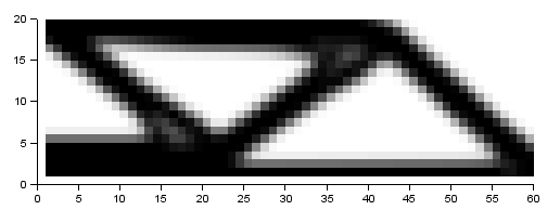
The classical example of minimizing compliance to obtain the optimal material distribution in the Messerschmitt-Bölkow-Blohm beam (MBB) problem has been chosen as the verification problem for the topology optimization algorithm. The model consists of a plate which is fixed at the bottom left and rests on a roller in the bottom right end. An edge load is applied in the top middle part. In the present study, only half the plate has been modeled and symmetry boundary conditions have been applied to the middle plane of the beam, as shown in Figure 7. The geometry, material properties, loads and optimization parameters were chosen similar to the problem solved by Sigmund [26]. The resulting volume fraction density distribution obtained by the web application is also shown in figure 7. This results are good agreement with distribution obtained by Sigmund [26].

4 Demonstration of Web Application
Truss configuration shown in Figure 2 has been considered for static analysis, limit state design and optimization of gusset plates. The loads were scaled by a factor of . The results from limit state design analysis are displayed in Table 2 where the cross sections as suggested by IS 800:2007 are shown along with the optimal values of the corresponding cross sectional areas. The optimized results evidently motivate the use of the suggested optimal design instead of the classical code-based design.
| Member | Forces (kN) | Length(m) | ISA L(mm) x B(mm) x t(mm) | Area (mm2) | Optimized Area (mm2) |
|---|---|---|---|---|---|
| 1 | -37.50 | 1.66 | 2 x ISA 20 x 20 x 4 | 290 | 150.00 |
| 2 | -24.99 | 1.66 | 2 x ISA 20 x 20 x 4 | 290 | 100.00 |
| 3 | -37.49 | 1.66 | 2 x ISA 20 x 20 x 4 | 290 | 150.00 |
| 4 | 40.38 | 1.34 | 2 x ISA 25 x 25 x 5 | 450 | 161.55 |
| 5 | 33.64 | 1.34 | 2 x ISA 40 x 25 x 3 | 376 | 134.59 |
| 6 | 9.76 | 0.65 | 1 x ISA 20 x 20 x 4 | 145 | 44.35 |
| 7 | -9.75 | 1.30 | 1 x ISA 20 x 20 x 4 | 145 | 45.59 |
| 8 | 33.64 | 1.34 | 2 x ISA 40 x 25 x 3 | 376 | 134.59 |
| 9 | -9.75 | 1.30 | 1 x ISA 20 x 20 x 4 | 145 | 45.59 |
| 10 | 9.76 | 0.65 | 1 x ISA 20 x 20 x 4 | 145 | 44.35 |
| 11 | 40.38 | 1.34 | 2 x ISA 25 x 25 x 5 | 450 | 161.55 |
In addition to this information, a detailed analysis report is generated in text format, as shown in Appendix A, which can be downloaded by the user. Appendix A shows results reported for one member under tension and another under compression and highlights the key differences in calculations related to the two cases.
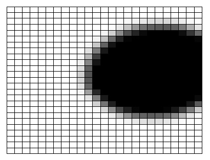
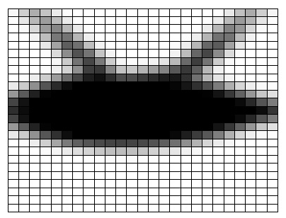
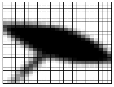
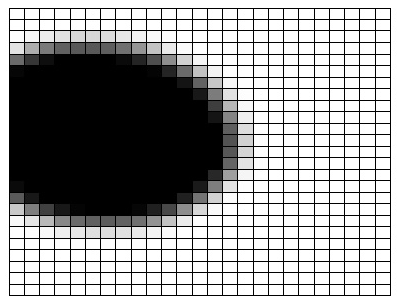
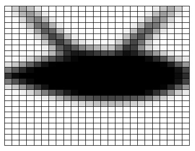
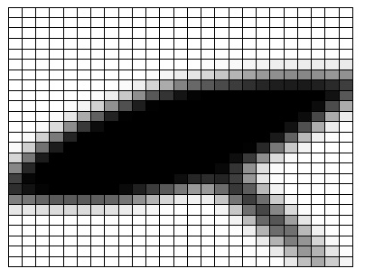
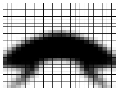
The web application displays the topology optimization results in the form of images. These optimal shapes of the gusset plates for the problem under consideration are shown in Figure 8. The gusset plates are identified by node numbers mentioned in Figure 2. Since the chosen truss system is symmetric about its central axis, the optimized shapes of the gusset plates are also expected to be symmetric in nature. This can be observed in the shapes of the gusset plates. Gusset plate 6 which is located on the symmetry line of the truss shows a symmetric shape. The shapes of Plates 1-4, 2-3 and 5-7 are mirror images of each other, which is also expected as these plates are symmetrically located with respect to the symmetry line of the truss.
5 Summary
A web-based tool has been developed which provides a single interface to analysis, design and topology optimization in the context of truss structures. The front end is delivered to the end user through a web browser utilizing the latest web technologies such as Three.js and HTML5. The core computation routines are executed on the server utilizing a combination of PHP, Scilab and DAKOTA. The analysis and design results are routed to the user in the form of tables, images, and downloadable text files.
The developed web application is the first of its kind that combines analysis and design with optimization and has immense potential both from an educational and industrial standpoint. The WebGL-based graphical user interface is intuitive and easy to use for both professionals and those who are new in the field. Current developments include extension of the web application to 3D and inclusion of constraints in optimization which would allow real time solution of realistic and practical problems.
Acknowledgements
The authors gratefully acknowledge the financial support provided by Indian Institute of Technology Gandhinagar that facilitated this work.
6 References
References
- Eynard et al. [2005] B. Eynard, S. Lienard, S. Charles, A. Odinot, Web-based collaborative engineering support system: applications in mechanical design and structural analysis, Concurrent engineering 13 (2005) 145–153.
- ANSYS [2011] ANSYS, Ansys inc., 2011.
- Adams et al. [2006] B. Adams, W. Hart, M. Eldred, D. Dunlavy, P. Hough, A. Giunta, J. Griffin, M. Martinez-Canales, J.-P. Watson, T. Kolda, DAKOTA, a Multilevel Parellel Object-oriented Framework for Design Optimization, Parameter Estimation, Uncertainty Quantification, and Sensitivity Analysis: Version 4.0 Uers’s Manual, United States. Department of Energy, 2006.
- Peng and Law [2002] J. Peng, K. H. Law, A prototype software framework for internet-enabled collaborative development of a structural analysis program, Engineering with Computers 18 (2002) 38–49.
- McKenna et al. [2000] F. McKenna, G. L. Fenves, M. H. Scott, B. Jeremic, Open System for Earthquake Engineering Simulation (OpenSees), University of California, Berkeley, CA, 2000.
- Ousterhout [1994] J. Ousterhout, Tcl and the Tk Toolkit, Addisonn-Wesley, C, 1994.
- Mathworks Inc [2014] Mathworks Inc, Matlab, 2014.
- Yang et al. [2004] Z. Yang, J. Lu, A. Elgamal, A web-based platform for computer simulation of seismic ground response, Advances in Engineering Software 35 (2004) 249–259.
- Cyclic1D [2015] Cyclic1D, http://cyclic.ucsd.edu, 2015.
- Gracia and Bayo [2013] J. Gracia, E. Bayo, Integrated 3D web application for structural analysis software as a service, Journal of computing in civil engineering 27 (2013) 159–166.
- Group [2009] T. Group, WebGL specification, 2009.
- Hejazi et al. [2014] F. Hejazi, M. Shahpasand, M. Mirnezhad, M. Jaafar, A. Ali, A web-based architecture for interactive finite element program, in: Computing in Civil and Building Engineering (2014), ASCE, pp. 1393–1400.
- Chen et al. [2006] H.-M. Chen, Y.-C. Lin, Y.-F. Chao, Application of web services for structural engineering systems, Journal of computing in civil engineering 20 (2006) 154–164.
- Weng [2011] W.-C. Weng, Web-based post-processing visualization system for finite element analysis, Advances in Engineering Software 42 (2011) 398–407.
- Alonso et al. [2007] J. M. Alonso, C. de Alfonso, G. García, V. Hernández, Grid technology for structural analysis, Advances in Engineering Software 38 (2007) 738–749.
- Alonso et al. [2008] J. M. Alonso, V. Hernández, G. Moltó, A high-throughput application for the dynamic analysis of structures on a grid environment, Advances in Engineering Software 39 (2008) 839–848.
- Chen and Lin [2008] H.-M. Chen, Y.-C. Lin, Web-FEM: An internet-based finite-element analysis framework with 3D graphics and parallel computing environment, Advances in Engineering Software 39 (2008) 55–68.
- Chen and Lin [2011] H.-M. Chen, Y.-C. Lin, An Internet-based computing framework for the simulation of multi-scale response of structural systems, Structural engineering & mechanics 37 (2011) 17.
- Tcherniak and Sigmund [2001] D. Tcherniak, O. Sigmund, A web-based topology optimization program, Structural and multidisciplinary optimization 22 (2001) 179–187.
- Sigmund [2014] O. Sigmund, Topopt, 2014.
- Paulino et al. [2005] G. H. Paulino, R. Page III, E. C. N. Silva, A java-based topology optimization program with web access: nodal design variable approach, in: 6th World Congress on Struct Multidisc Optim Book of Abstracts, volume 1471, Citeseer, pp. 135–135.
- Nobel-Jørgensen et al. [2014] M. Nobel-Jørgensen, N. Aage, A. N. Christiansen, T. Igarashi, J. A. Bærentzen, O. Sigmund, 3d interactive topology optimization on hand-held devices, Structural and Multidisciplinary Optimization (2014) 1–7.
- BIS [????] BIS, IS 800:2007 General construction in steel: Code of practice, ????
- Scilab Enterprises [2012] Scilab Enterprises, Scilab: Free and Open Source software for numerical computation, Scilab Enterprises, Orsay, France, 2012.
- Vanderplaats [1973] G. Vanderplaats, CONMIN a FORTRAN program for constrained function minimization, Technical Report TM X-62282, NASA, 1973.
- Sigmund [2001] O. Sigmund, A 99 line topology optimization code written in matlab, Structural and Multidisciplinary Optimization 21 (2001) 120–127.
- Bendsøe [1995] M. Bendsøe, Optimization of Structural Topology, Shape, and Material, Springer, 1995.
Appendix
Appendix A Details of steel design of truss (Figure 2) as per IS:800-2007
Steel Design of Member No:1 (Tension Member)

Yeild Strength of Steel(fy): 250.00 N/mm$^2$
Ultimate Strength of Steel(fu): 410.00 N/mm$^2$
Force in the member(F): 3.75 kN
Length of the member(Lo): 1.67 m
Providing double angle section
Area of each Section Required to resist the force:8.25mm$^2$
Assuming Weld Size: 4 mm
  Strength of Weld= weld_size*0.7*0.462*fu: 530.38 N/mm$^2$

Section Selected: 20 x 20 x 4 mm
  Gross Area of Section(Ag): 145.00 mm$^2$
  Net Area of Section(An): 145.00 mm$^2$

Strength of Selected Section:-
  Strength due to yeilding of Gross Area=
  (0.91*Ag*fy)/1000=32.99 kN
  Strength due to rupture of Net Area=
  (0.8*0.8*An*fu)/1000=38.05 kN
  Strength due to Block Shear:
    Tb1=((0.525*Avg*fy+0.72*Atn*fu)/1000): 56.27 kN
    Tb2=(0.416*Avn*fu+0.91*Atg*fy)/1000: 60.63 kN
  Strength due to Block Shear:56.27 kN

Tensile Strength of Selected Section:32.99 kN > 1.88 kN

Check For Slenderness Ratio Limits:-
  Effective Length of the member=Le=(Lo*1.0):1.67 m
  Minimum Radius of Gyration=Rmin:0.58 mm
  Slenderness Ratio of the member=
  (Le*1000)/Rmin:287.50 < 350

Provide 2 angle 20 x 20 x 4 with weld size 4 mm all
along all three edges.

Steel Design of Member No:4 (Compression Member)

Yeild Strength of Steel(fy): 250.00 N/mm$^2$
Ultimate Strength of Steel(fu): 410.00 N/mm$^2$
Force in the member(F): 4.04 kN
Length of the member(Lo): 1.35 m
Providing double angle section
Area of each Section Required to resist
the force: 22.44 mm$^2$
Section Selected: 20 x 20 x 4 mm
  Area of Section(Ag): 145.00 mm$^2$

Check For Section Classification:-
  Shorter Arm to thickness ratio
  b/t=5.00 < (15.7*e=15.70)
  Longer Arm to thickness ratio
  L/t=5.00 < (15.7*e=15.70)
  Sum of Shorter Arm and   Longer Arm to thickness
  ratio: (L+B)/t=10.00 < (25*e=25.00)
Hence full area of section is effective.

Strength of Selected Section using equations:
  (Design Compressive Strength)
  f_cd=(fy/$\lambda_m$)/sqrt($\phi$+($\phi^2$-$\lambda^2$)))
  $\lambda_{vv}$=((Lo/rmin)/e*sqrt(E$\pi^2$/fy))= 1.19
  $\lambda_{\phi}$=(((L+b)/2*t)/e*sqrt(E$\pi^2$/fy))= 0.06

Assuming Hinged Connection:
  k1=0.7 k2=0.6 k3=5
  $\lambda_{eh}$=sqrt(k1+k2*$\lambda_{vv}^2$+k3*$\lambda_{\phi}^2$)= 1.25
  $\phi$=0.5*[1+$\alpha$($\lambda_{eh}$-0.2)+$\lambda_{eh}^2$]= 1.54
  c=($\phi$+sqrt($\phi^2$-$\lambda_{eh}^2$))= 2.44
  f_cd=(fy/$\gamma_{mo}$)/sqrt($\phi$+($\phi^2$-$\lambda^2$)))=93.24 N/mm$^2$

Assuming Fixed Connection:
  k1=0.2 k2=0.35 k3=20
  $\lambda_{ef}$=sqrt(k1+k2*$\lambda_{vv}^2$+k3*$\lambda_{\phi}^2$)=0.87
  $\phi$=0.5*[1+$\alpha$($\lambda_{ef}$-0.2)+$\lambda_{ef}^2$]=1.04
  c=($\phi$+sqrt($\phi^2$-$\lambda_{ef}^2$))= 1.62
  f_cd=(fy/$\gamma_{mo}$)/sqrt($\phi$+($\phi^2$-$\lambda^2$)))= 140.42 N/mm$^2$

Interpolating values for hinged and fixed connection:
  $\lambda_e$=$\lambda_{eh}$-[($\lambda_{eh}$ - $\lambda_{ef}$)*(0.15/0.35)]= 1.09
  $\phi$=0.5*[1+$\alpha$($\lambda_{e}$-0.2)+$\lambda_{e}^2$]= 1.31
  c=($\phi$+sqrt($\phi^2$-$\lambda_{e}^2$))=2.04
  f_cd=(fy/$\gamma_{mo}$)/sqrt($\phi$+($\phi^2$-$\lambda^2$)))=111.52 N/mm$^2$

Design Compressive Force:(f_cd*A)=16.17 kN > 2.02 kN

Check For Slenderness Ratio Limits:-
  Effective Length of the member=  Le=(Lo*1.0):1.35 m
  Minimum Radius of Gyration=Rmin:1.27 mm
  Slenderness Ratio of the member=
  (Le*100)/Rmin:105.72 < 180

Provide 2 angle 20 x 20 x 4 with weld size 4 mm all
along all three edges.