On Stability of Targets for Plasma Jet Induced Magnetoinertial Fusion
Abstract
The compression and stability of plasma targets for the plasma jet-induced magneto-inertial fusion (PJMIF) have been investigated via large scale simulations using the FronTier code capable of explicit tracking of material interfaces. In the PJMIF concept, a plasma liner, formed by the merger of a large number of radial, highly supersonic plasma jets, implodes on a magnetized plasma target and compresses it to conditions of the fusion ignition. A multi-stage computational approach for simulations of the liner-target interaction and the compression of plasma targets has been developed to minimize computing time. Simulations revealed important features of the target compression process, including instability and disintegration of targets. The non-uniformity of the leading edge of the liner, caused by plasma jets as well as oblique shock waves between them, leads to instabilities during the target compression. By using front tracking, the evolution of targets has been studied in 3-dimensional simulations. Optimization studies of target compression with different number of jets have also been performed.
1 Introduction
In the Plasma Jet Induced Magneto-inertial Fusion PJMIF concept [1, 2], a plasma liner, formed by the merger of a large number of radial, highly supersonic plasma jets, implodes on a magnetized plasma target and compresses it to conditions of the fusion ignition. By avoiding major difficulties associated with both the traditional laser driven inertial confinement fusion and solid liner driven MTF, the plasma-liner driven magneto-inertial fusion potentially provides a low-cost and fast R&D path towards the demonstration of practical fusion energy.
A simplified PJMIF model was theoretically studied in [3], proposing scaling laws and the analysis of target compression rates, deconfinement times, and fusion energy gains. A number of numerical simulations have also been performed for the liner and target systems in spherically-symmetric geometry. These include 1D Lagrangian simulations [4], front tracking simulations of the liner - target interface [5, 6], 3D SPH simulations of the converging liner [8], and 3D simulations with resolution of oblique shock waves and atomic processes (ionization) of the merger of high Mach number argon jets and the formation and implosion of liners [7]. The simulation effort was recently complemented by experiments conducted at Los Alamos National Laboratory [9, 10, 11], in which a single supersonic argon plasma jet produced by a pulsed-power-driven plasma railgun, and a merger of two such jets were studied.
All previous three-dimensional simulations studies [6, 8] have focused only on the structure and state of plasma liners during the merger and implosion process. In this paper, we report results of simulation study of a plasma target compressed by a liner formed by the merger of 90 argon plasma jets. Simulations use the front tracking capability of the FronTier code [12], critical for accurate resolution of large density discontinuity of the plasma - liner interface. Front tracking is also important for correct description of the change of material properties across the interface as the argon liner is described by a weakly ionized plasma equation of state with the resolution of atomic processes [6], while the target is in a fully ionized plasma state described by the ideal gas equation of state. MHD processes in the target were not included. MHD forces in the real magnetized target may be strong, providing significant stabilizing effect. The reason to ignore MHD effects was partly motivated by current plans to perform experiments on the compression of gas targets first, before using magnetized targets. While the FronTier code [12] is capable of the simulation of MHD in geometrically complex domains within the method of front tracking, the currently implemented MHD regime, so called the low magnetic Reynolds number approximation, is suitable for weakly ionized plasmas but not for fully ionized plasma in the target. The implementation of ideal MHD with front tracking will be performed in the future.
To obtain simulation of such a multiscale process as the propagation of free plasma jets, their merger, formation and implosion of liners, and compression of targets, a multi-stage simulation method was designed. It is described in detail in the next section. Simulations were performed on a parallel supercomputer. The FronTier code demonstrates good parallel scalability. It has been used for large scale simulations on various platforms including USA Leadership Computing Facilities. FronTier was the basis of INCITE 2011 and 2012 supercomputing awards to study uncertainty quantification for turbulent mixing and combustion.
2 Numerical Methods
Front tracking is a hybrid Lagrangian - Eulerian computational method in which a lower-dimensional Lagrangian mesh, called the interface, moves through a volume-filling Eulerian mesh and tracks discontinuities or distinguished waves. FronTier is a multiphysics code based on front tracking that implements various hydrodynamic flow regimes. FronTier is capable of robustly handling geometrically complex interfaces and resolving their topological changes. It supports compressible and incompressible Navier-Stokes equations, MHD equations in the low magnetic Reynolds number approximation [12], phase transitions [13], combustion and turbulent mixing. It has been broadly used for multiple applications including high power mercury jet targets for future accelerators [14, 17, 18], cryogenic pellet fueling of nuclear fusion devises [15, 16], and nuclear fission applications.
The multi-stage scheme for the overall simulation is discussed in the next section together with simulation results.
3 Analysis of Simulation Results
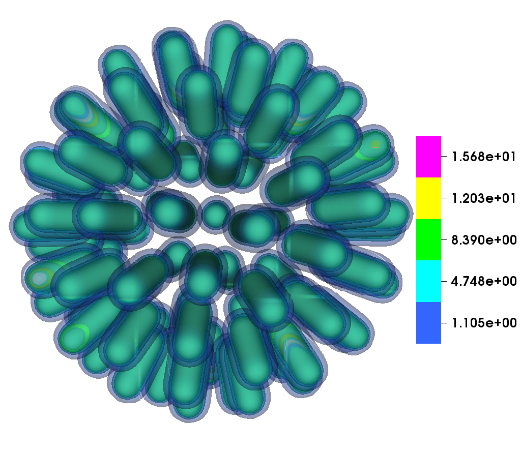
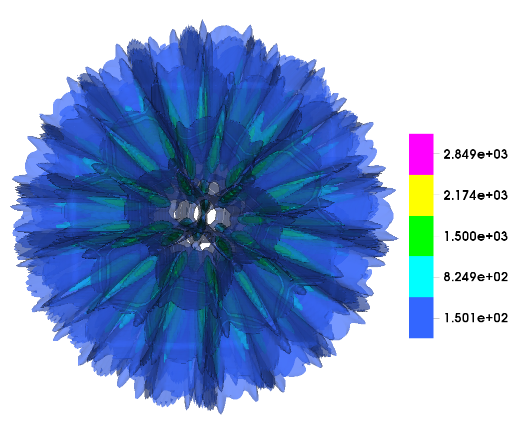
First we perform cylindrically-symmetric, 2-dimensional simulation of the propagation of a single detached argon jet from the nozzle of the plasma gun. Here we use the code features that include high-resolution hyperbolic solvers based on the Riemann problem, front tracking, and weakly ionized plasma EOS model with atomic processes. The argon jet has the following initial conditions: the initial inner and outer radii are 137.2 cm and 162.7 cm, respectively, density , pressure , velocity , and Mach number . The ambient vacuum is modeled as rarefied gas with density and pressure . The computational mesh size is 2 mm. After obtaining the pressure, density, and velocity profiles for the single jet before the merger, we first find directions for 90 jets uniformly distributed in space using Spherical Centroidal Voronoi Tessellation (SCVT), and then initialize states of 90 jets before the merger in a 3-dimensional code. We perform transformation from 2-dimensional cylindrical coordinate into 3-dimensional Cartesian coordinate together with bi-linear interpolation, which initializes the states around each jet direction. The initial mesh size at this stage is 5 mm which we found to be sufficient for the resolution of the jet-merger process. This mesh size is further refined as the simulation progresses. The target is not included in this coarser simulation since we only need the liner information before liner-target interaction. Figures 1 and 2 depict the density and pressure contours before and after the jet merger. Due to oblique shock waves, we observe redistribution of states in the converging liner. At the later stage, the highest pressure and density appear along the plane of interaction of the neighboring jets. This non-uniform distribution causes the instabilities on the target. We also observe the contours with shapes of pentagon and hexagon determined by the location of jets.
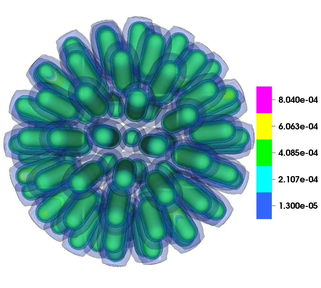
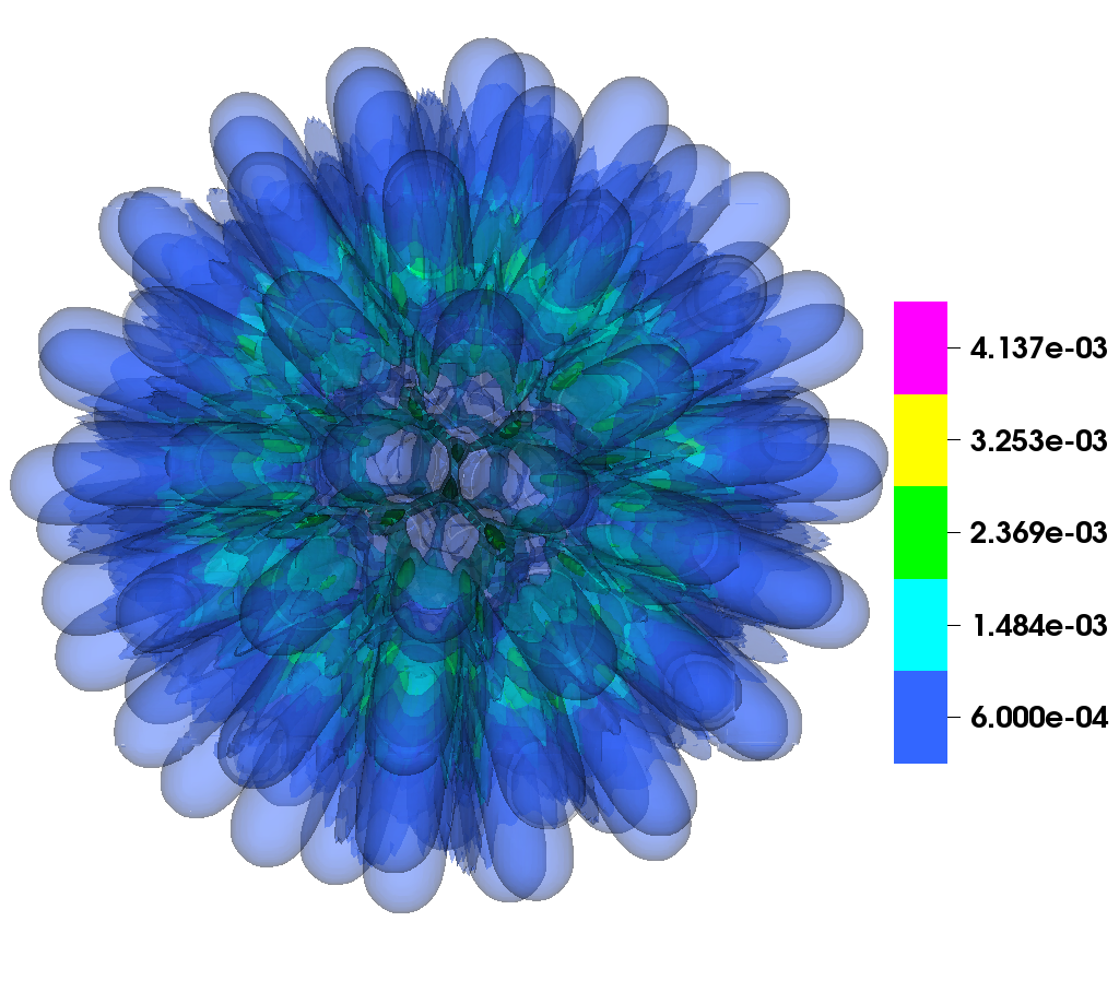
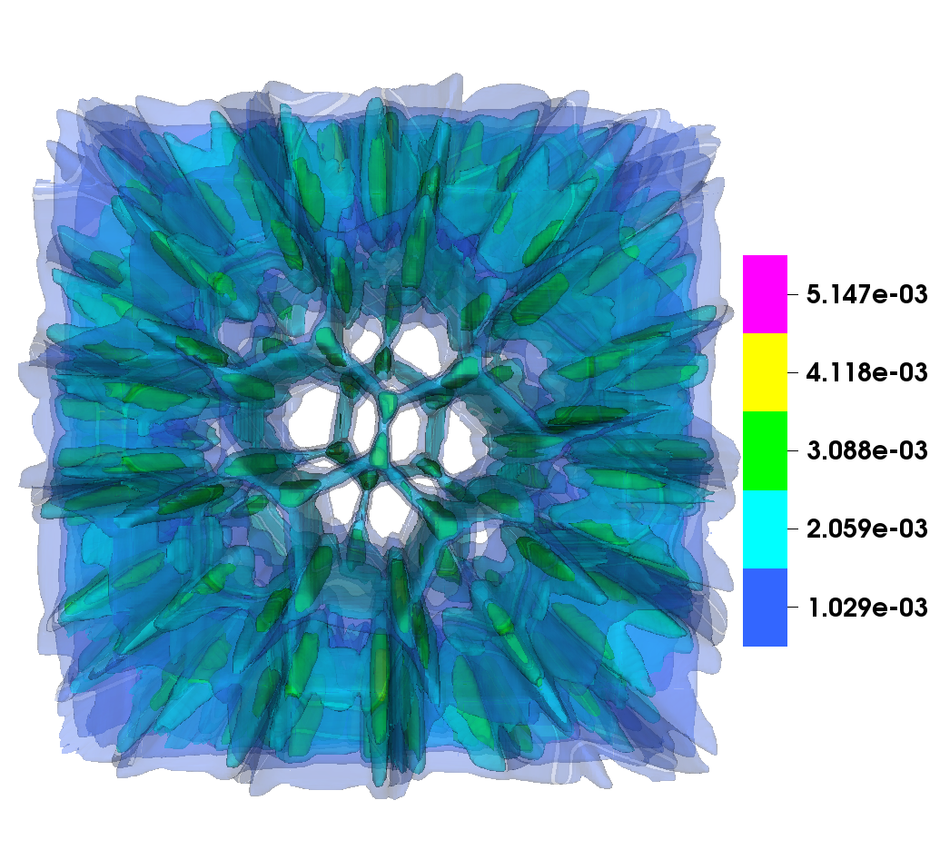
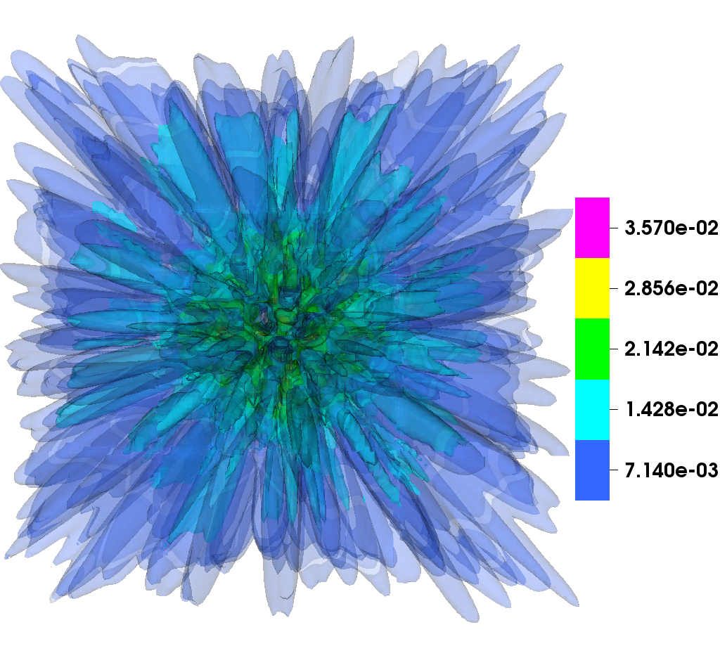
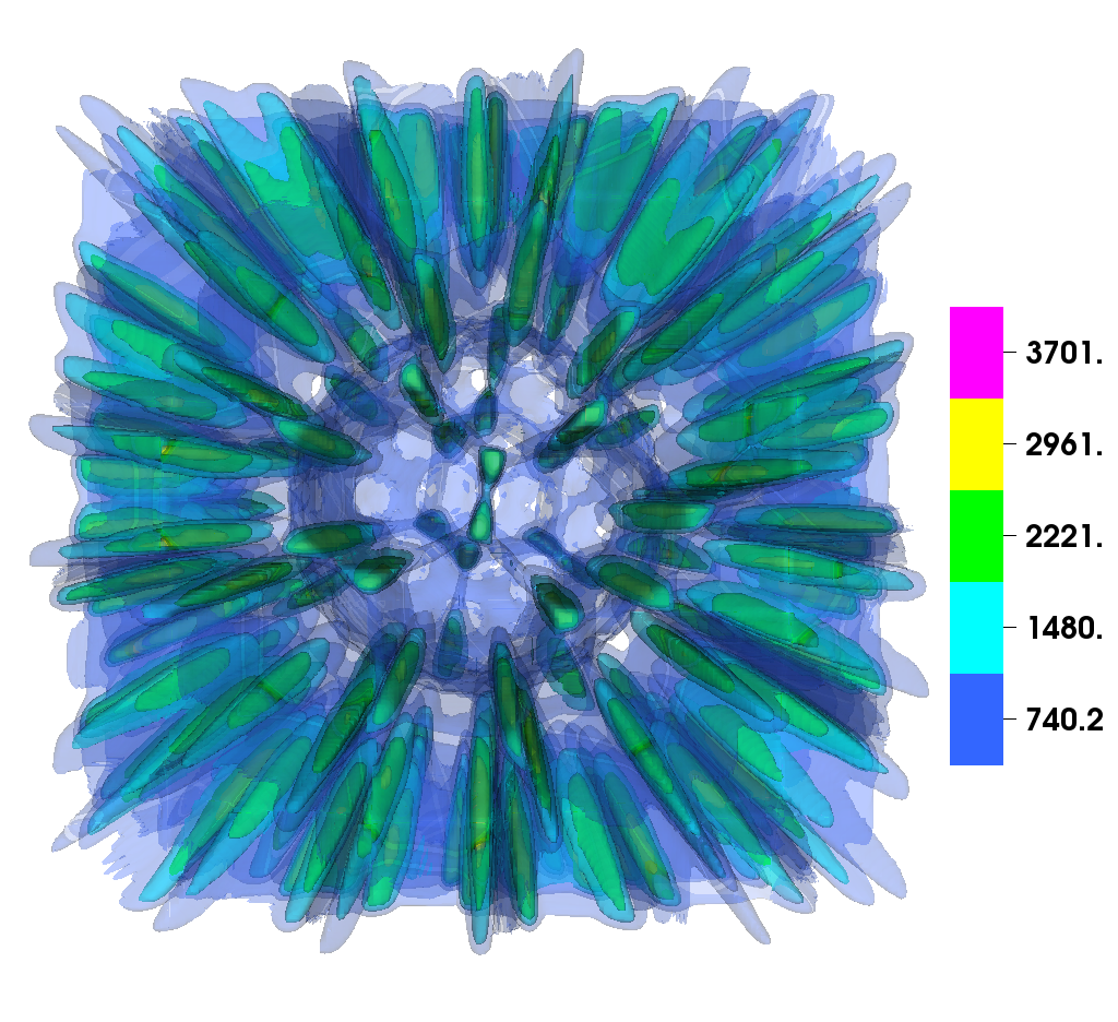
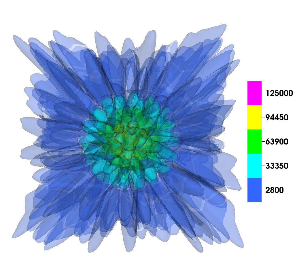
Finally, we take the data of the center area from the previous simulation when the liner still remains at some small distance off the target, and re-initialize a refined simulation for the target compression study. The target initial condition is as follows: density , pressure . In order to prevent target diffusion, we set the velocity of the target to be zero before the liner-target interaction. As the target is compressed by a non-uniform liner, it develops surface instabilities and even brakes in fragments at the late stage. The target behavior is unstable and complicated after this stage and we currently only focus on the properties of the target before it brakes into fragments. Figure 3 and Figure 4 depict density and pressure contours evolution in the center region including liner and target. Figure 4 shows the interaction between the liner and target with formation of bubbles and spikes on the target at later stage. Here spikes are inward pointing toward the target and bubbles are outward pointing toward the liner. The region with higher density and pressure along the plane of interaction of the neighboring jets compresses the target with higher rate and bubbles and spikes are obtained. The instabilities are amplified with time. In order to inspect the evolution of the target more clearly, we present the evolution of target together with pressure distribution on the interface in Figure 5. The maximum pressure appears on the spikes, in the region of interaction of the neighboring jets which is also the region of the maximum pressure for the liner due to oblique shock waves. The target finally breaks because of this uneven pressure distribution. Figure 6 shows the properties of bubbles and spikes. The bubble and spike heights keep increasing, and the terminal bubble velocity becomes quasi-constant around , before the breakup of the target.
Finally, we perform 1-dimensional spherical symmetric simulation corresponding to a 3-dimensional uniform liner to compare with the full 3-dimensional simulation and quantify the role of non-uniformities and instabilities of the liner and target. The initial conditions, obtained by the averaging of the 3-dimensional data in angular coordinates, are as follows: the inner and outer radii are 137.2 cm and 162.7 cm respectively, the density , pressure , velocity , and Mach number . Figure 7 shows the average pressure in the target for different cases. Note that we only focus on the time range of the target compression before fragmentation. The pressures of the 3-dimensinal (90 jets) case and 2-dimensional (16 jets) case are very close to each, around and respectively at the end of this time range. The pressure of uniform cases is always higher as expected because of the impact of oblique shock waves for jet case. The 3-dimensinal uniform case (1-dimenstional spherical geometry) is around while the 2-dimensinal uniform case (1-dimenstional cylindrical geometry) is around . The pressure of 3-dimensinal uniform case is almost 80 times higher than that of the 90 jets case. Similar simulations of a self-implosion of liners (without a target) produce the difference of stagnation pressure between a 3-dimensional simulation and the corresponding 1-dimensional uniform problem of about 50 times.
We would like to emphasize that current simulations were performed at conditions compatible with capabilities of the experimental facility at Los Alamos National Laboratory. The achievable pressures and temperatures in targets are well below the fusion ignition. Therefore we do not comment on the fusion energy gain in this work.
4 Conclusions
In this paper, we investigated the compression and stability of plasma targets for the plasma jet induced magneto-inertial fusion (PJMIF) via large scale simulations using the FronTier code capable of explicit tracking of material interfaces. A multi-stage computational approach for simulations of the liner-target interaction and the compression of plasma targets has been developed to minimize computing time. Simulations involve the propagation of a single supersonic argon plasma jet, the merger of 90 jets and the formation of a plasma liner, the implosion of the liner, and the compression of a plasma target. Simulation show the formation and evolution of oblique shock waves during the jet merger process, consistent with previous studies. These shock waves reduce the average Mach number of the liner and its ability to compress the target, and determine to a large extent the nonuniform properties of the imploding liner. Simulations revealed important features of the target compression process, including instability and disintegration of targets. The non-uniformity of the leading edge of the liner, caused by plasma jets as well as oblique shock waves between them, leads to instabilities during the target compression. Optimization studies of target compression with different number of jets have also been performed.
5 Acknowledgement
Research was partially supported by a DOE OFES grant.
References
- [1] Y. C. F. Thio, E. Panarella, R. C. Kirkpatrick, C. E. Knupp, F. Wysocki, P. Parks, and G. Schmidt, in Current Trends in International Fusion Research II, edited by E. Panarella, National Research Council Canada, Ottawa, 1999.
- [2] S. C. Hsu et al., Spherically Imploding Plasma Liners as a Standoff Driver for Magnetoinertial Fusion, IEEE Trans. Plasma Sci. 40, 1287 (2012).
- [3] P. Parks, Phys. Plasmas 15, 062506, 2008.
- [4] T. J. Awe, C. S. Adams, J. S. Davis, D. S. Hanna, and S. C. Hsu, One-dimensional radiation-hydrodynamic scaling studies of imploding spherical plasma liners, Phys. Plasmas 18, 072705 (2011).
- [5] R. Samulyak, P. Parks, and L. Wu, Spherically symmetric simulation of plasma liner driven magnetoinertial fusion, Phys. Plasmas 17, 092702 (2010).
- [6] H. Kim, R. Samulyak, L. Zhang, and P. Parks, Influence of atomic processes on the implosion of plasma liners, Phys. Plasmas 19, 082711 (2012).
- [7] H. Kim, L. Zhang, R. Samulyak, P.Parks, On the structure of plasma liners for plasma jet induced magnetoinertial fusion, Phys. Plasmas 20, 022704 (2013).
- [8] J. T. Cassibry, M. Stanic, S. C. Hsu, S. I. Abarzhi, and F. D. Witherspoon, ?Tendency of spherically imploding plasma liners formed by merging plasma jets to evolve toward spherical symmetry,? Phys. Plasmas 19, 052702 (2012).
- [9] S. C. Hsu, E. C. Merritt, A. L. Moser, T. J. Awe, S. J. E. Brockington, J. S. Davis, C. S. Adams, A. Case, J. T. Cassibry, J. P. Dunn, M. A. Gilmore, A. G. Lynn, S. J. Messer, and F. D. Witherspoon, ?Experimental characterization of railgun-driven supersonic plasma jets motivated by high energy density physics applications,? Phys. Plasmas 19, 123514 (2012).
- [10] E. C. Merritt et al., Experimental Characterization of the Stagnation Layer between Two Obliquely Merging Supersonic Plasma Jets, Phys. Rev. Lett. 111, 085003 (2013).
- [11] E. C. Merritt et al., Experimental evidence for collisional shock formation via two obliquely merging supersonic plasma jets,Phys. Plasmas 21, 055703 (2014).
- [12] R. Samulyak, J. Du, J. Glimm, Z. Xu, A numerical algorithm for MHD of free surface flows at low magnetic Reynolds numbers, J. Comp. Phys., 226 (2007), 1532 - 1549.
- [13] S. Wang, R. Samulyak, T. Guo, An embedded boundary method for parabolic problems with interfaces and application to multi-material systems with phase transitions, Acta Mathematica Scientia, 30B (2010), No. 2, 499 - 521.
- [14] R. Samulyak, W. Bo, X. Li, H. Kirk, K. McDonald (2010), Computational algorithms for multiphase magnetohydrodynamics and applications, Condensed Matter Physics, 13, No 4, 43402: 1 - 12.
- [15] R. Samulyak, T. Lu, P. Parks, (2007). A magnetohydrodynamic simulation of pellet ablation in the electrostatic approximation, Nuclear Fusion, 47, 103-118.
- [16] P. Parks, T. Lu, R. Samulyak (2009). Charging and E x B rotation of ablation clouds surrounding refueling pellets in hot fusion plasmas, Physics of Plasmas, 16, 060705.
- [17] A. Hassanein at el., An R&D program for targetry and capture at a neutrino factory and muon collider source, Nuclear Instruments and Methods in Physics Research Section A: Accelerators, Spectrometers, Detectors and Associated Equipment, 501 (1), 70 - 77.
- [18] R. Samulyak, Y. Prykarpatskyy, T. Lu, J. Glimm, Z. Xu, M.-N. Kim, Comparison of heterogeneous and homogenized numerical models of cavitation, International Journal for Multiscale Computational Engineering, 4 (2006), No 3, 377 - 389.