Focusing effect of bent GaAs crystals for -ray Laue lenses: Monte Carlo and experimental results
Abstract
We report on results of observation of the focusing effect from the planes (220) of Gallium Arsenide (GaAs) crystals. We have compared the experimental results with the simulations of the focusing capability of GaAs tiles through a developed Monte Carlo. The GaAs tiles were bent using a lapping process developed at the cnr/imem - Parma (Italy) in the framework of the laue project, funded by ASI, dedicated to build a broad band Laue lens prototype for astrophysical applications in the hard X-/soft -ray energy range (80-600 keV). We present and discuss the results obtained from their characterization, mainly in terms of focusing capability. Bent crystals will significantly increase the signal to noise ratio of a telescope based on a Laue lens, consequently leading to an unprecedented enhancement of sensitivity with respect to the present non focusing instrumentation.
Keywords:
Laue lens astrophysics bent crystals hard X-ray telescopes X-ray diffraction.1 Introduction
In hard X-/soft -ray astrophysics there is a strong need to investigate new technologies and detection methods capable of overcoming the limits exhibited by current operational telescopes, both in terms of sensitivity and angular resolution. In the near future, Laue lenses made from bent crystals will have a key role in the hard X-/soft -ray astronomy thanks to the technological progress made in the engineering and in the material science fields. One of the most attractive properties of the Laue lenses is the possibility to increase the collecting surface without increasing the detection area and consequently the detector noise.
To date, mosaic crystals have been used to build a number of prototype capable to demonstrate the real possibility to build Laue lenses. Mosaic crystals are composed of small blocks, called crystallites, with a size approximately varying from 1 to 100 m. The crystallites are assumed to be perfect crystals. The lattice orientation of these crystallites are distributed around a main direction typically following a Gaussian distribution.
In the sixties, about 4000 NaCl mosaic crystals have been used to focus the broad band 20-130 keV Lindquist68 . The mosaicity of about 0.5∘ resulted in a very wide energy response for each crystal but with low diffractive power. During the 1980s, the Argonne National Laboratory of the University of Chicago studied both mosaic and bent crystals and many different designs for the crystal lenses also developing a full size crystal diffraction lens made to cover the energy range from 200 keV to 1 MeV. Later, in a project in collaboration with the CESR laboratory at the University of Toulouse, a lens for astrophysics was built Smither95 and for the first time an astrophysical source was observed (the Crab nebula) during a stratospheric flight (the CLAIRE project Halloin04 ). More recently, in the project named HAXTEL (Hard X-ray TELescope) small prototypes of Laue lenses have been built and successfully tested to demonstrate the capability to set a number of mosaic Cu crystals with an accurate positioning system in a reasonable short time capable to focus energy of 100 keV Frontera07 ; Virgilli11a . However, although flat crystals have the advantage of a relatively easy production in large quantity with good reproducibility in terms of dimensions and mosaic spread, they have limits that can be summarized as follows:
-
•
even without taking into account the absorption in the crystals, their maximum reflectivity is limited to 50 which is the result of a radiation equilibrium between direct and diffracted beam from the crystalline planesZachariasen .
-
•
a flat mosaic crystal tile does not display a focusing effect. Its diffracted image in the focal plane mainly depends on the crystal size and on the crystal mosaic spread which results in a defocusing effect Lund2005 .
Since the sensitivity of a Laue lens strongly depends on the photon distribution on the focal plane, crystals capable of focusing the photons on a small PSF are very promising. Bent crystals can overtake one or both the mentioned limits, depending on their particular nature. Two curvatures, that are conceptually different, can be present in a bent crystal. A curvature of the planes perpendicular to the X-ray beam can be induced (external curvature also named focusing curvature). Thanks to the external curvature, bent crystals can focus the radiation at the focal plane detector into an area that is much smaller than the crystal cross section itself. Such a focusing effect can be observed for crystals with both perfect or mosaic structure. A secondary curvature can be present if the internal diffraction planes are also bent (such a secondary curvature can be induced by the external curvature). For bent perfect crystals have been demonstrated that the secondary curvature increases their efficiency at values higher than the 50% of the incident radiation Malgrange02 which is the theoretical insurmountable limit for flat crystals. Also for bent mosaic crystals, there are evidences that the curvature of the diffracting planes of the crystallites provides an efficiency that is larger than that of the equivalent flat mosaic crystalsferrari13b .
Bent crystals can be produced in a variety of methods Smither05 . Curved diffractive planes are obtained by growing a two-component crystal where the relative concentration of the two components changes as the crystal is grown. An example of two component crystal has been grown at the IKZ - Berlin where Si-Ge crystals were grown with starting concentration of 3-7 percent of Germanium keitel99 . Perfect Si crystals were bent by applying a thermal gradient to a single structure crystal Smither05 . Nevertheless, the power required to keep the curvature stable for each crystal of an entire Laue lens is too high and impracticable. Instead, a mechanical bending can be more practical for astrophysical applications Kawata01 given that a self-standing curvature does not require additional power. Self-standing Si and Ge perfect crystals were produced and characterized at Sensor and Semiconductor Laboratory (Ferrara, Italy) by bending through mechanical grooving of one of their surfaces Bellucci11 . Although a good uniformity is achieved, the grooving process causes damage in the crystal. As a consequence, the crystal itself suffer from a high mechanical fragility and the diffraction efficiency is limited to 50 if the diffraction occurs in the layers beside and beneath the grooves Camattari14 . A self-standing curvature obtained by cnr/imem - Parma Buffagni11 relies on a controlled mechanical damaging on one surface of the sample. The procedure introduces defects in a superficial layer of a few microns, providing a highly compressive strain responsible for the convexity appearing on the worked side.
For the laue project virgilli13 , devoted to the building of Laue lenses for space astronomy in the hard X-ray energy band (80–600 keV), self standing bent crystals are being used. The tiles made of Gallium Arsenide (220) ferrari14 ; buffagni15 and Germanium (111) camattari2012 have been bent using the two described method of lapping procedure and surface grooves, respectively. As the Laue lens has been designed with a focal length of 20 m, the crystals have been prepared with a curvature radius of 40 m.
In this paper we show the capability of a sample of GaAs mosaic crystals to strongly focus the radiation at the correct distance from the tile, if they are bent with the proper curvature radius. We also have studied the experimental set-up with a geometrical/analytic approach and with Monte Carlo simulations. Both the cases of point like and extended X-ray source of radiation and their effect on the photon distribution on the focal plane detector are discussed and compared with the results obtained with the laboratory beam line.
We show our capability to describe the diffraction process through the simulations in case of source of radiation placed at a finite distance. The experimental results are in excellent agreement with the expectations. Such a validation give us the confidence that the simulations made with a source of radiation placed at infinitive distance (astrophysical case) are also correct.
2 A comparison between flat and bent crystals: Monte Carlo simulations
All the simulations presented in this paper have been made with the LLL (Laue Lens Library) software developed by the laue project team. The code is developed for a complete description of Laue lenses made of mosaic or perfect crystals, with flat or bent structure, for a source of radiation placed at either a finite distance or infinitely far from the target. The software is based on a ray tracer that takes into account the diffraction laws, the absorption caused by crystals of different materials and by the lens frame and allows the spatial distribution of the photons at a given distance from the crystal after the X-ray diffraction to be determined. Different geometries of the lens have been implemented, as it is possible to select between single crystals, rings of crystals, sectors (petals) or entire lenses made of crystals set in concentric rings or in spiral configuration. The software assumes an ideal focal plane X-ray imager detector (whose size can be adapted to the particular application) with spectral capability. The ray tracer and the detector are integrated in a unique software platform which has a single input front-end (where the crystal properties, the space between the crystals, the lens focal length, the energy pass-band must be defined) providing the physical configuration of the simulated lens (total weight of the lens, spatial dimensions, total geometric area) and its scientific features (output energy pass-band, photon distribution on the focal plane, effective area, sensitivity).
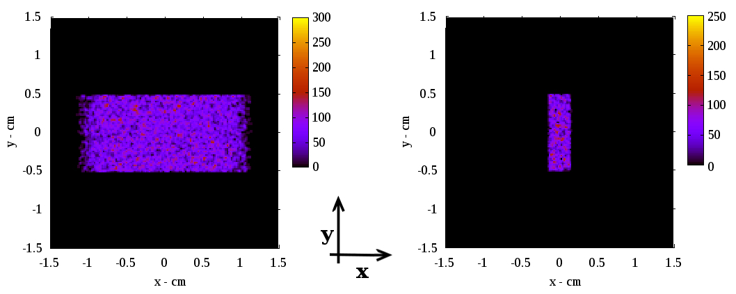
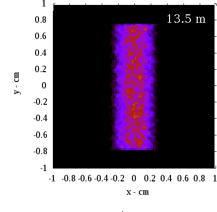
When a infinitely far source impinges over a flat perfect crystal, the radiation encounters the diffractive planes with the same Bragg angle, as the source of radiation has no divergence. The result is that the diffracted image has the same size as the crystal cross section itself. In the case of a mosaic crystals, the mosaic spread results in a defocusing effect and the size of the diffracted image is given by the convolution between the crystal size itself and its mosaicity. Figure 1(left) shows the diffracted signal from the (220) planes of a flat mosaic GaAs crystal with mosaicity of 15 arc seconds, cross section 30 10 mm2, 2 mm thick, when an X-ray beam of dimension 20 10 mm2 impinges on it. The beam size was set smaller than the crystal cross section itself to avoid undesired border effects. The simulated x-rays have a uniform distribution of 106 photons in the energy range 149.7 - 150.3 keV which is roughly the pass-band offered by the defined mosaicity when the Bragg angle is set to diffract the centroid energy of 150 keV.
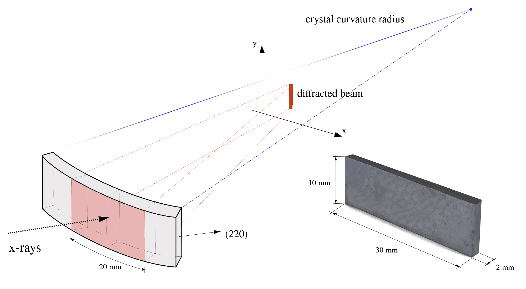
A comparison is made with the simulation of the diffracted beam from the (220) planes of a bent GaAs mosaic crystal having the same dimensions and mosaic spread, but with 40 m curvature radius (Fig. 1, right). As exemplified in the sketch of Fig. 2, the spot dimension is strongly reduced by the focusing effect dictated by the curvature of the crystal in the curvature direction, even if the mosaic defocusing is still present. The result is that for a bent crystal the space distribution of the photons in the focal plane along the x direction is smaller than the crystal length. Differently, no focusing effect is expected in the other direction, thus along the y profile the width of the diffracted image has the same size of the crystal. It is also worth noting that for a bent crystal the energy pass-band is much wider than that shown by a flat GaAs and and for the particular case, it turns out to be in the range 148.5 keV - 151.5 keV.
3 Effects of the source divergence
The focusing effect shown in Fig. 1 (right panel) is obtained for the case of a source of radiation placed at infinite distance. Unfortunately, in the laboratory the source of radiation is at a finite distance from the crystal and the focusing effect as obtained from an astrophysical source cannot be directly observed. It can be demonstrated that the combination of the sample curvature and the divergence of the incoming beam makes the radiation focus at a different focal distance, depending on the separation between the radiation source and the crystal.
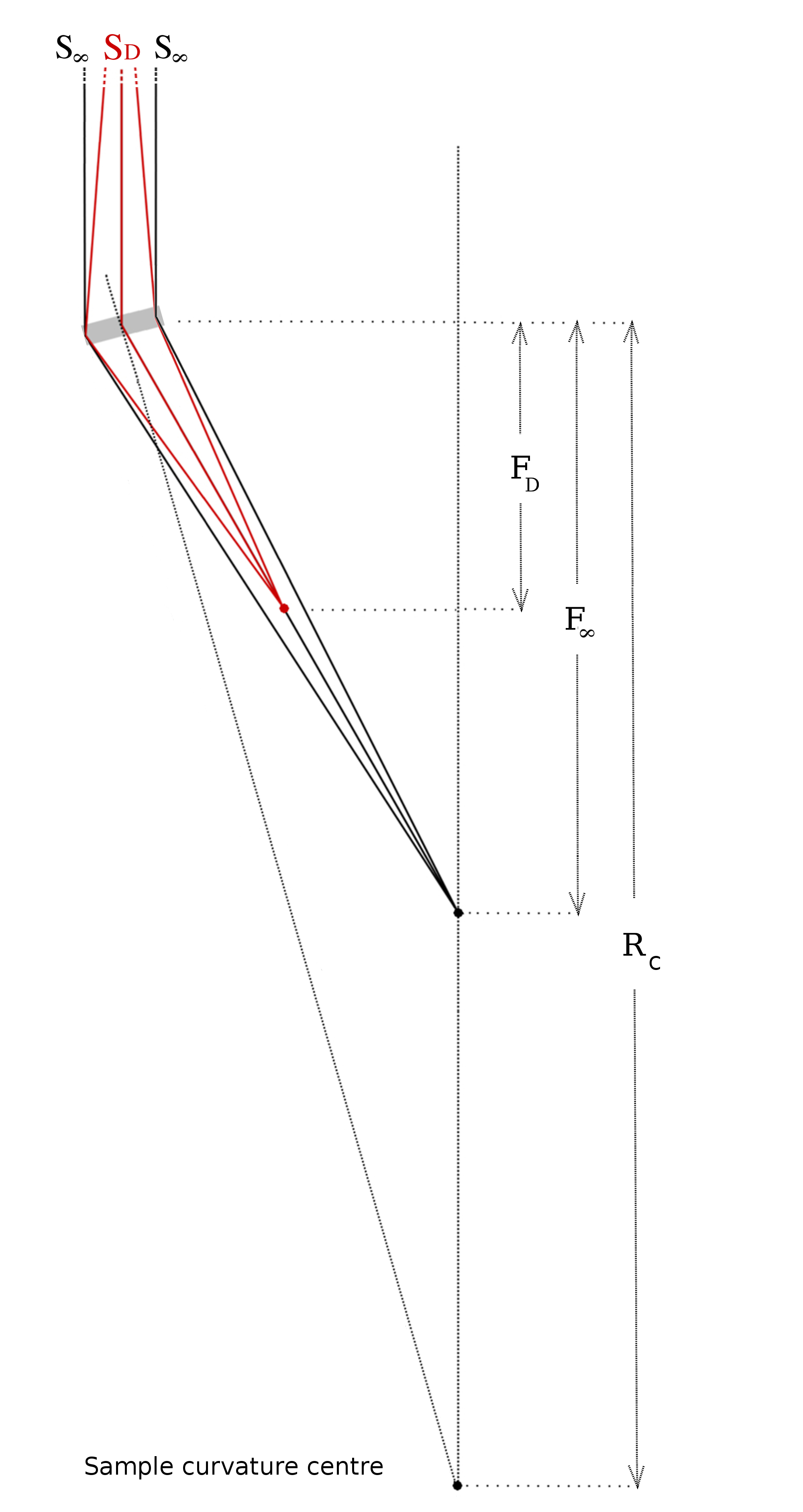
A geometrical explanation of the effect can be deduced. Let us assume a crystal sample with cross section (bent along the direction ) irradiated by a source placed at infinite distance with no divergence. If is the corresponding Bragg angle for the radiation impinging at the center of the sample (Figs. 3 and 4), the Bragg angles at the extreme points of the sample along its length depend on and on the curvature radius of the sample :
| (1) |
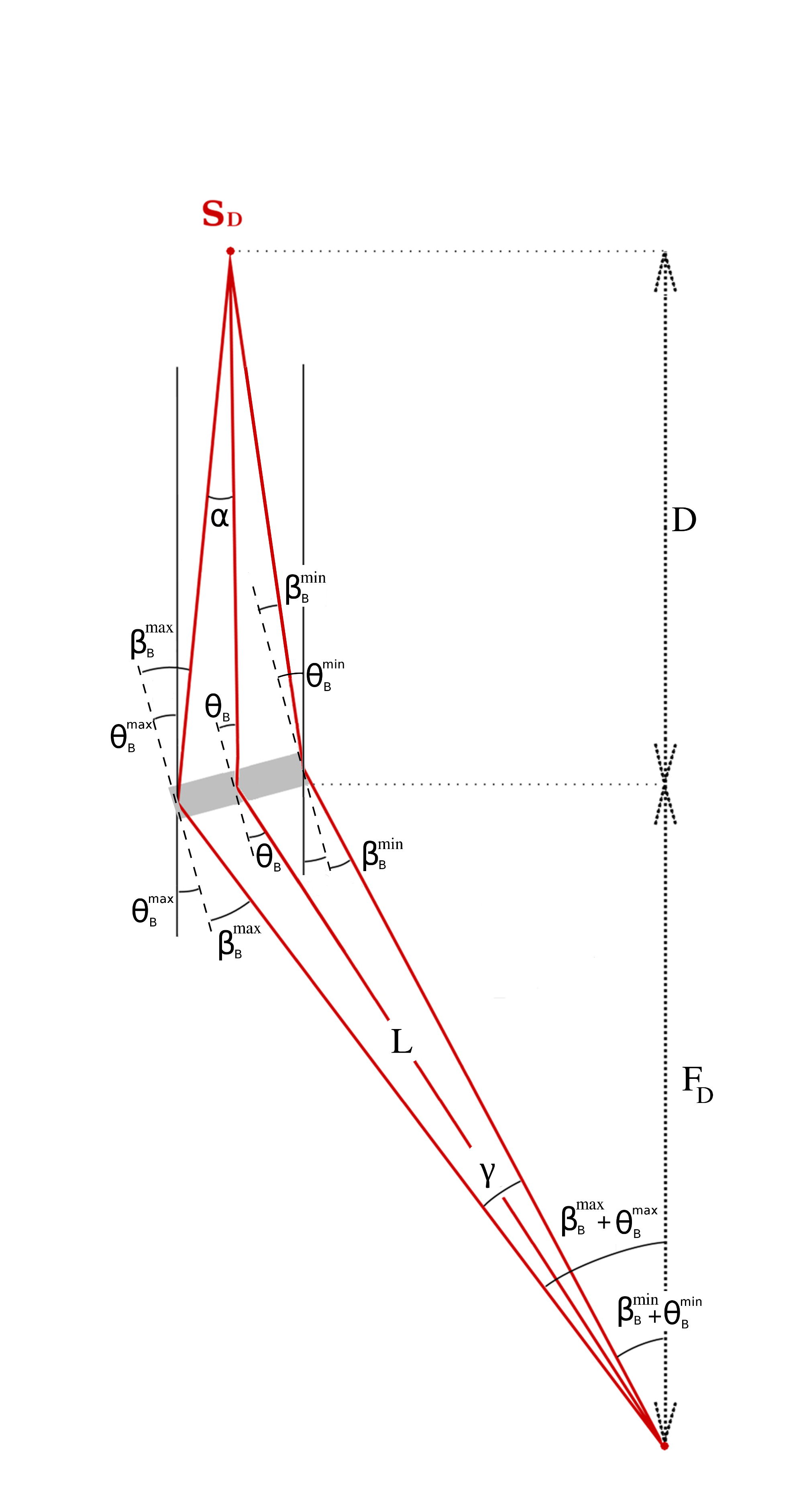
Under these conditions, the diffracted radiation is focused at the point = /2 (see Fig. 3). On the other hand, if the source of radiation is placed at a finite distance (see Fig. 4), the Bragg angle at the center of the crystal does not change with respect to the case of an infinitely far source ( = ) while, due to the combined effect of the divergence angle and the curvature angle , at the extreme points of the sample the diffraction angles are defined as follows:
| (2) |
and the radiation is focused at a different focal distance . To calculate the value of it is convenient to consider the following relations (see Fig. 4):
That together give:
in which the value of is defined as:
| (3) |
The value of the new focal distance is then determined as a function of the sample curvature and the source distance and does not depend on the beam size over the target.
For small diffraction angles () the relation becomes:
| (4) |
Instead, with no approximations, the focal distance depends on energy and its variation is 12 mm 90 keV and 3 mm 200 keV.
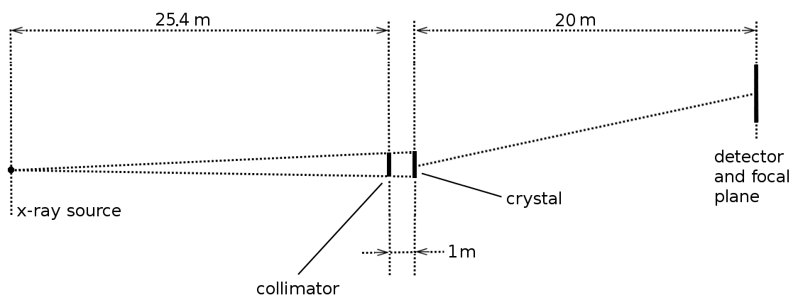
This approach allows the value of the best focal distance to be determined, for a crystal whose curvature radius is known. Indeed the curvature of a sample can be independently estimated by using the method of the K line. The method is based on the estimation of the tilt angle required to diffract the K energy (59.20 keV) along the crystal length. Being curved the crystal surface, the required angle changes along the crystal length and the curvature can be calculated from the slope of the linear relation between the crystal coordinate hit by the radiation and the required tilt angle providing the diffracted energy. The method is extensively described in Liccardo12 where the achieved accuracy in the curvature radius estimation was within 2%. In the case of the larix facility loffredo03 ; Virgilli11a ; larix the source is at the distance distance = 26.40 0.02 m from the sample, then for a crystal sample with a curvature radius of 40 m, the best focal distance is = 11.39 m.
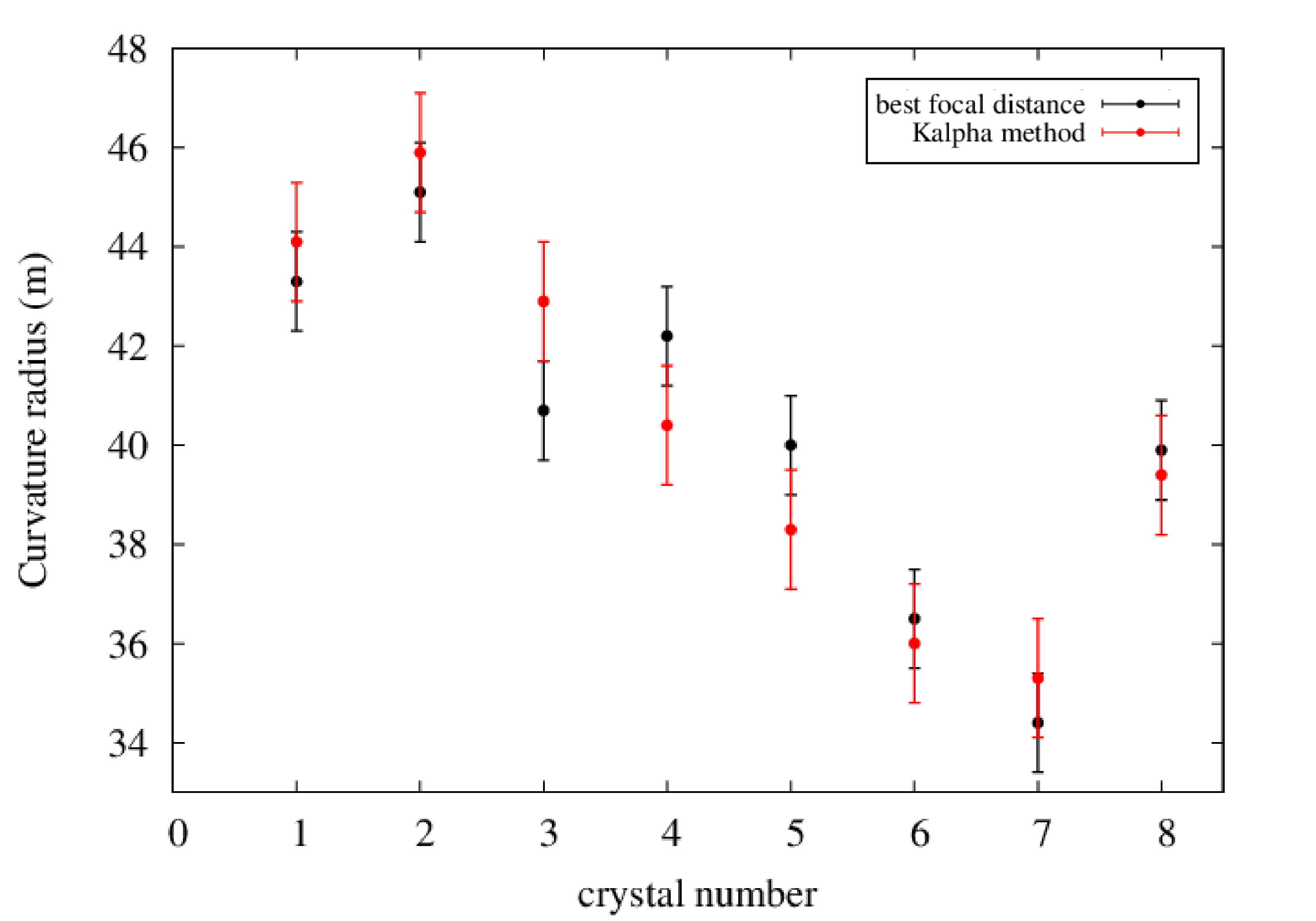
Alternatively, for a fixed value of , it is possible to calculate the curvature radius of a sample by simply measuring the value of that is the distance at which the width of the psf is minimized. The method of the distance can be validated if compared with the described K method and the experimental comparison is shown in in Fig. 5 where the values of the curvature radius have been estimated for a sample of 8 crystals. The methods are in good agreement within the uncertainties.
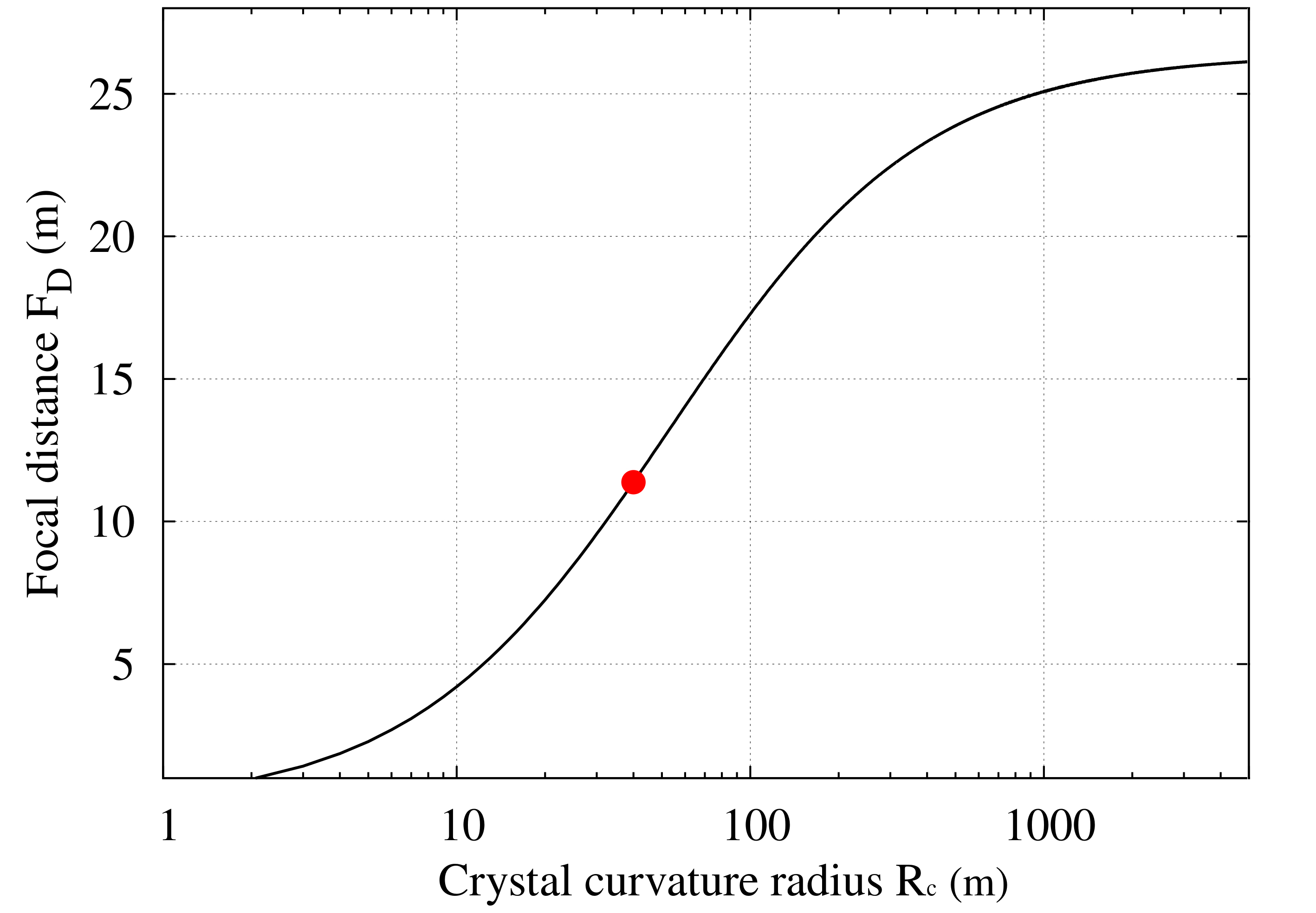
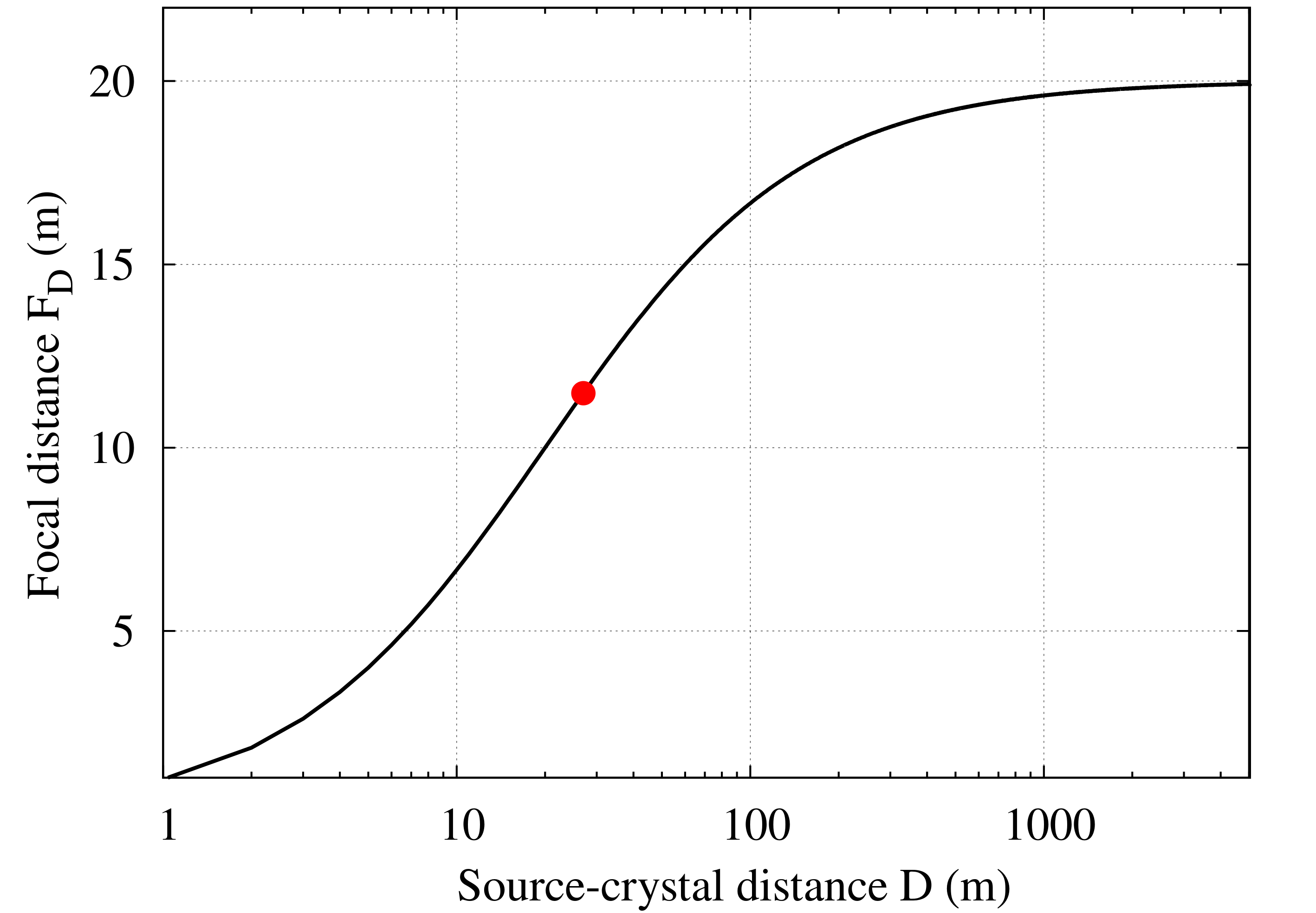
It is interesting to discuss the expectations of Eq. 4 in the limiting cases of a flat crystal or a source placed at infinite distance. In the case of a flat crystal ( ) for a source at finite distance (e.g., = 26.40 m), it turns out that the focusing position occurs at = , as expected (see Fig. 6, left panel). On the other hand, if the crystal curvature radius is fixed, and , then = , also as expected. The dependence of on for a fixed curvature radius is shown in Fig. 6, right panel.
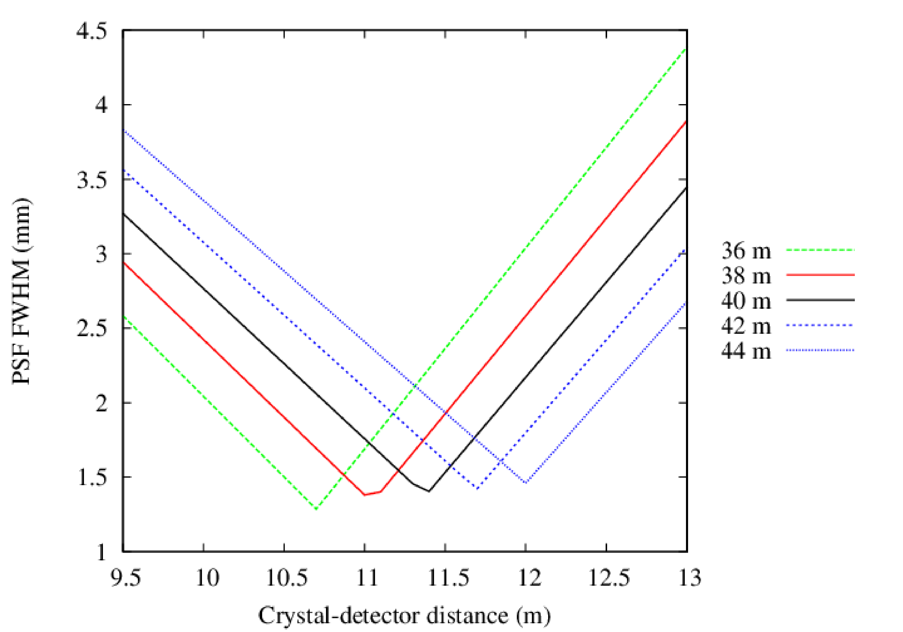
In addition to the ray tracer, a geometrical method have been developed to derive the Full Width at Half Maximum (fwhm) of the Point Spread Function (psf) as a function of the crystal-detector distance for a given value of the curvature radius of the crystal. In this approach the determination of the fwhm is obtained by considering the mutual distance between the diffracted X-rays coming from the two extreme points of the crystal at different distances, taking into account the crystal intrinsic angular spread, the beam divergence, and the curvature effect along the direction. The results based on this analytic/geometric calculation, as a function of the crystal-detector distance and for various crystal curvature radii, are shown in Fig. 7.
4 Effects of the extended dimensions of the X-ray source
The ray tracer have been also used to estimate the effect of an extended source of radiation on the photon distribution on the focal plane and to compare the result with that achievable with a point-like source of radiation. Indeed, a real X-ray tube source has a finite dimension that cannot be neglected. In the larix facility, the X-ray tube employed for the measurements is equipped with two interchangeable targets where the radiation is generated (foci):
-
•
small source (ss): size 0.35 0.45 mm2 (800 W);
-
•
large source (ls): size 0.85 0.95 mm2 (1800 W).
The Monte Carlo simulations allow us to derive the dependence of the psf x profile (i.e., along the diffraction direction) on the source size. A uniform photon distribution in the 100-300 keV energy range was assumed, with the source kept at a distance of 26.40 m from the crystal, while the source size was varied with different size from 0 to 3 mm.
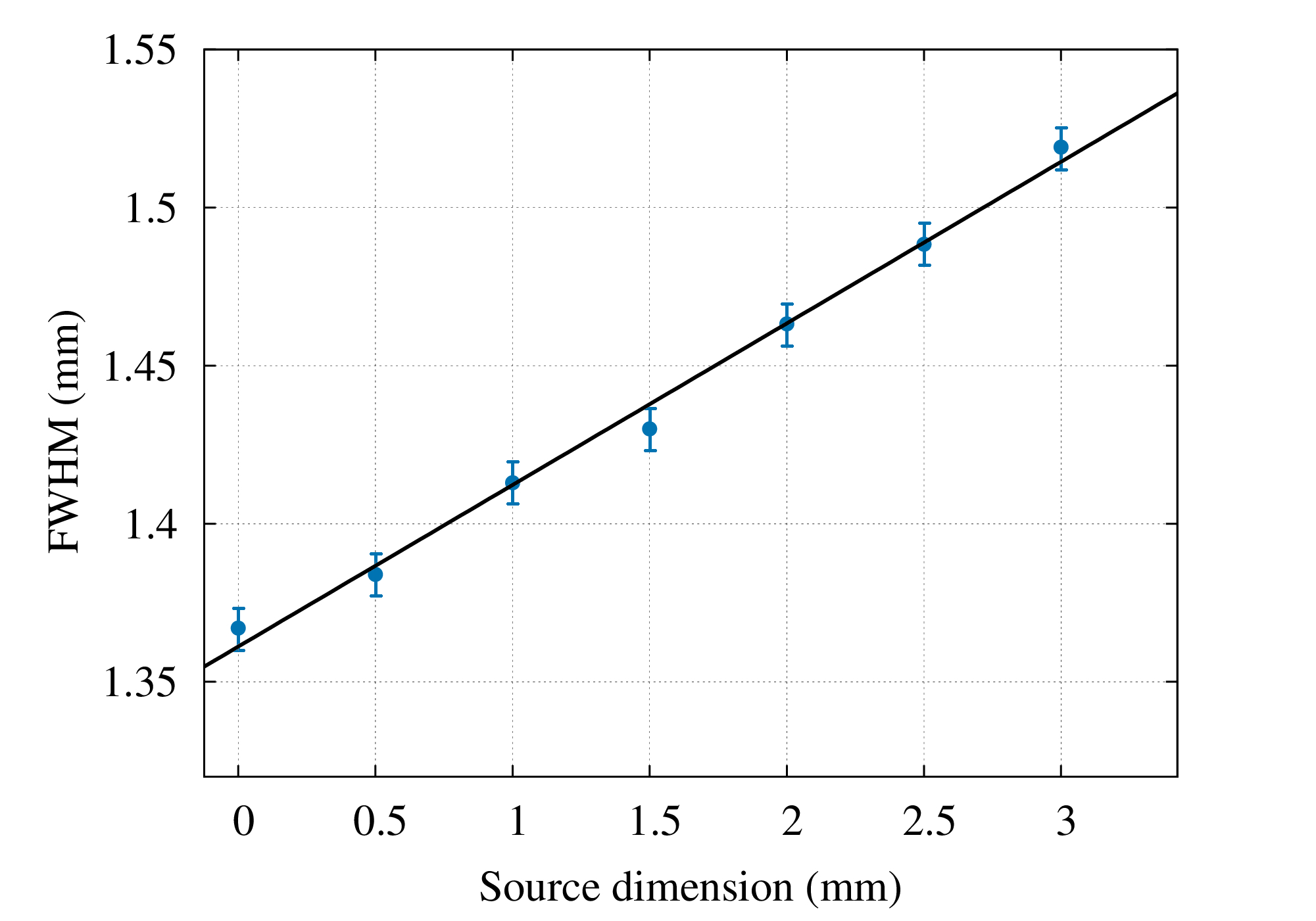
It is evident from Fig. 8 that there is a linear dependence between the dimension of the extended source in the calculation of the psf fwhm. In the ideal case of a point like source the psf fwhm results to be 1.365 mm which only depends on the mosaicity of the sample, assumed for our purposes to be = 20 arc seconds. Instead, for the given value of the mosaicity, the minimum psf fwhm using the equipped ss and ls results fwhmSS 1.38 and fwhmLS 1.41, respectively.
5 Effect of the finite distance of the source
Monte Carlo simulations also provide information on the psf produced by a crystal when the radiation source is placed at a finite distance from the crystal. It is worth noting that a Laue lens for space applications does not suffer of divergence effects, while, being the lens developed on ground, the source is at a finite distance and the beam divergence cannot be neglected.
Simulations have been made assuming a source at infinite distance and at a distance m. In the latter case, it is assumed that the radiation is emitted from the ss of the X-ray tube. In both the cases the radiation impinges over an area of 20 10 mm2 centered on the 30 10 mm2 GaAs (220) crystal with a curvature radius m. The diffracted beam is observed at the nominal focal distance of 20 m. The results are shown in Fig. 9 (top panels), together with the x and y distribution profiles (bottom panels).
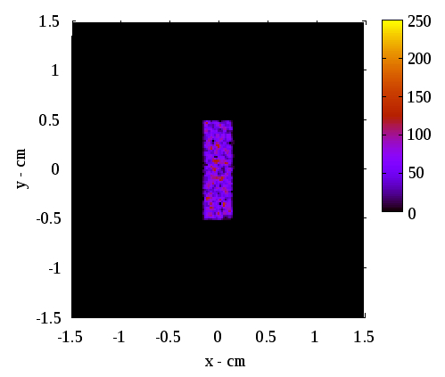
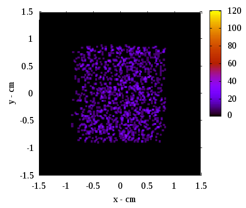
The apexes and indices used in the following definition of fwhm are self-explanatory. Along the y direction, as expected, the focusing effect is not present and the divergence effect is only present in the case of a source placed at finite distance D. Under these conditions we get fwhm 17.5 mm and fwhm 10.0 mm which is the crystal dimension itself along the y direction. Regarding the x direction, the value fwhm 2.9 mm is mainly related to the mosaic spread of the sample. Instead, in the case of the source placed at 26.40 m, it drastically increases (fwhm 16.5 mm) due to a defocusing effect dictated by the combination of the beam divergence with the curvature of the sample.
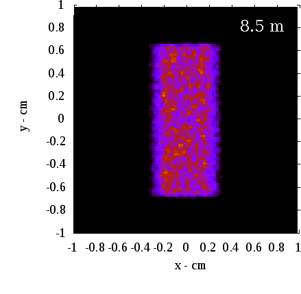
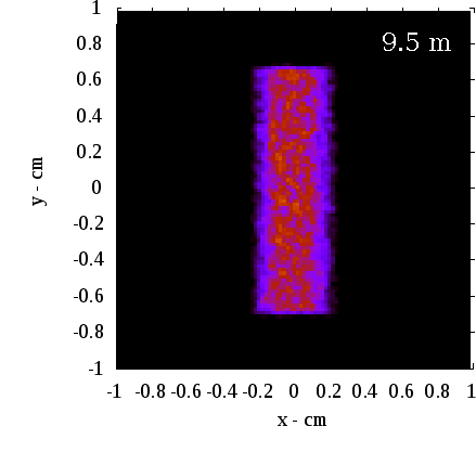


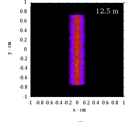
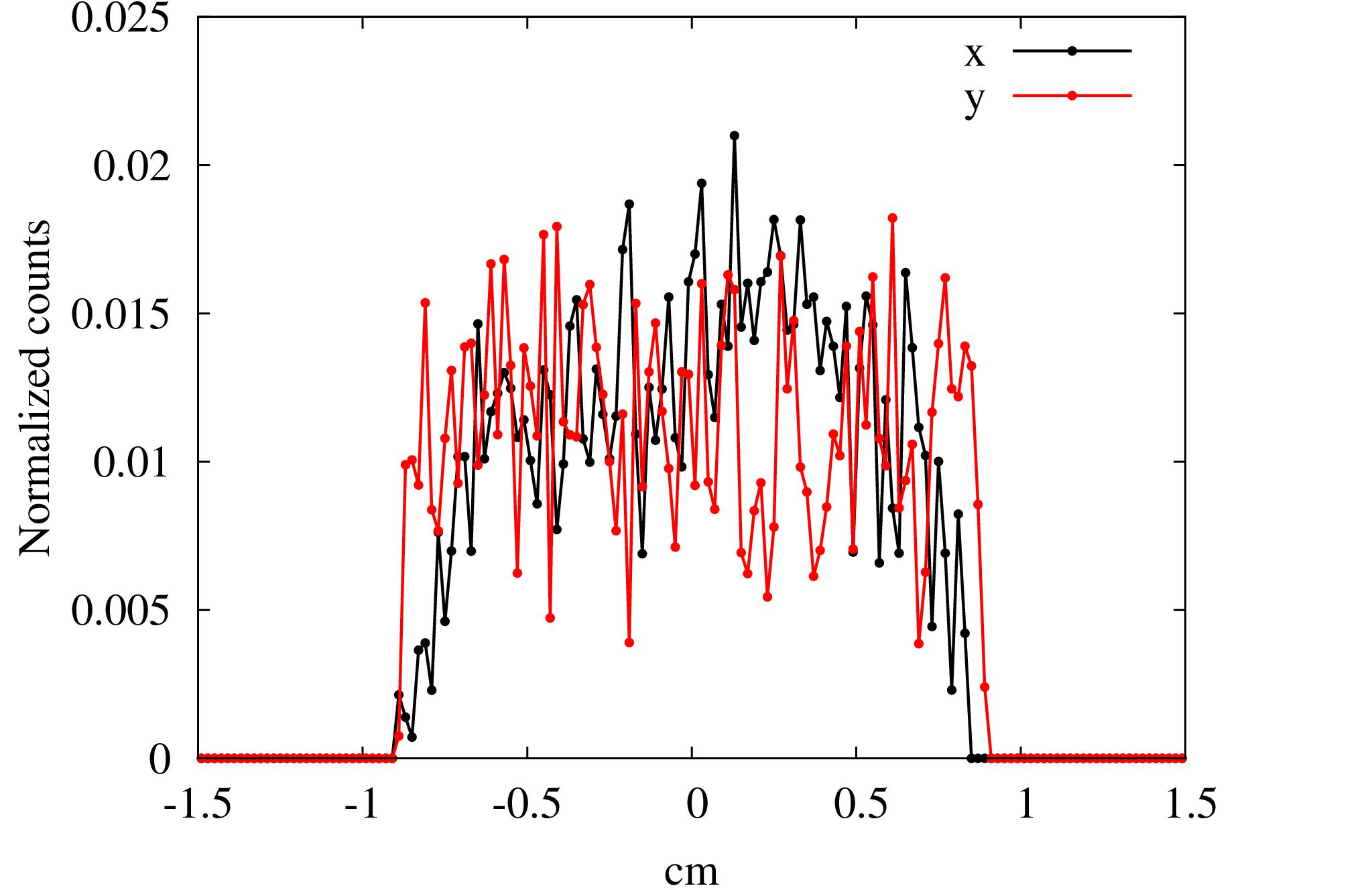
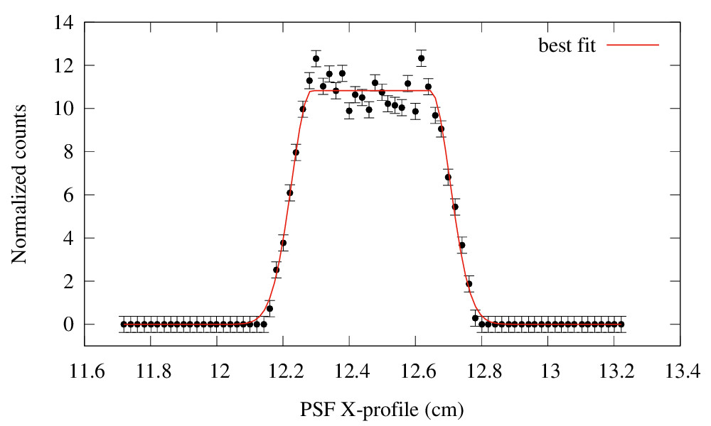
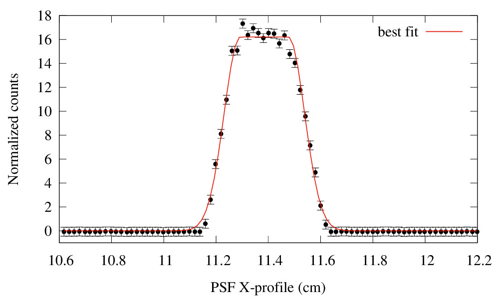
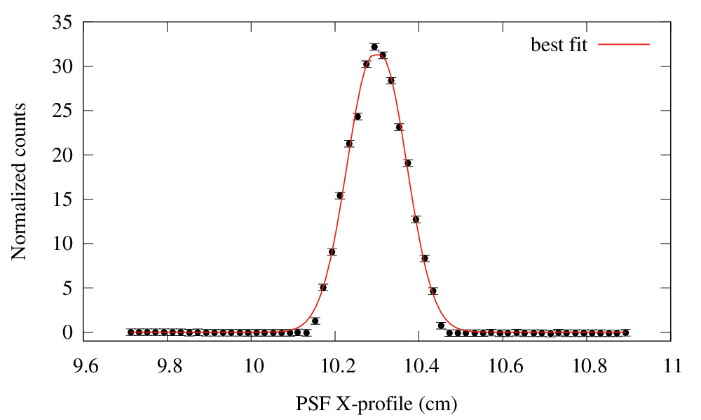
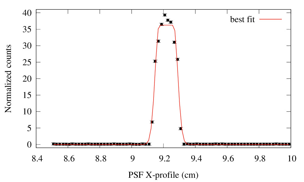
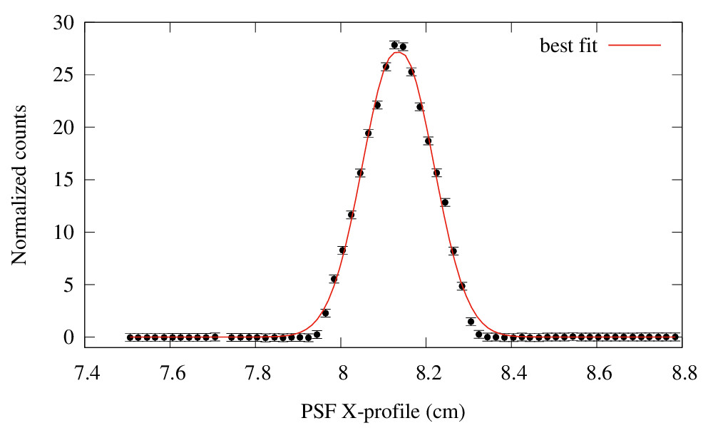
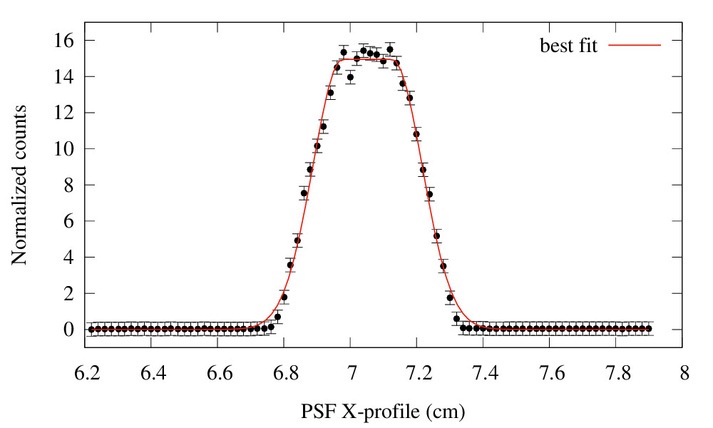
The defocusing effect observed in Fig. 9 (right panels) is expected and can be removed if the diffracted beam is observed at a closer distance from the crystal. Figure 10 shows the spatial distribution of the signal when the diffracted photons are collected at different distances from the sample (from 8.5 m to 13.5 m). The minimum fwhm of the psf is obtained by collecting the photons at 11.4 m from the crystal, in agreement with the analytical calculations (Eq. 4).
In Fig. 11 are also shown the x profiles of the images acquired at different distances with the red line representing is the best fit function. A satisfactory function is represented by a convolution between a Gaussian profile with a fixed value of fwhm and a rectangular function with variable width. Within this explanation, the width of the Gaussian function represents the angular spread which is constant along the entire crystal length. In the experimental case the mosaicity of the sample was of 15 arc seconds. When the diffracted image is acquired at the expected focal distance the spread of the photon distribution is comparable with the Gaussian spread, given that all the rays are converging almost in a point. Instead, out of the focus the Gaussian profile is uniformly spread into a larger area which is analytically described by the rectangular function, whose width depends on the distance of the detector from the best focal distance.
6 Experimental set-up
The results of the simulations have been validated through an experimental run performed in the larix facility. The larix equipment has been extensively described elsewhere Virgilli11b ; virgilli13 . As portrayed in Fig. 12, the distance between the source and the target is 26.40 0.02 m, while the distance between the collimator and crystal is 1 0.02 m. All the degrees of freedom of the subsystems are entirely motorized as required for the alignment procedures. The collimator blades can be also remotely adjusted in order to set the vertical and the horizontal beam dimensions.
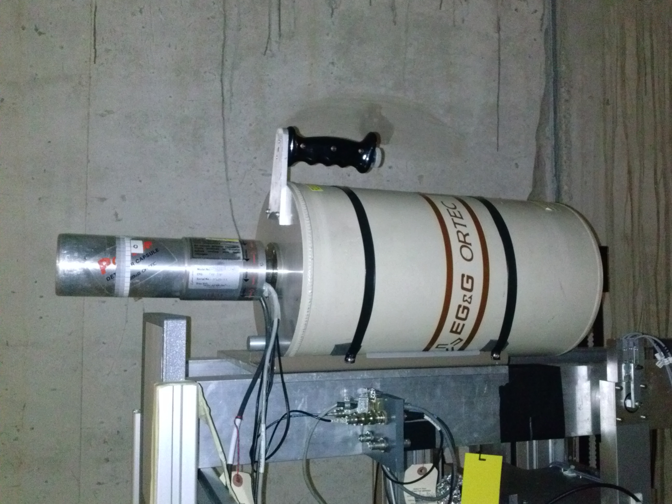
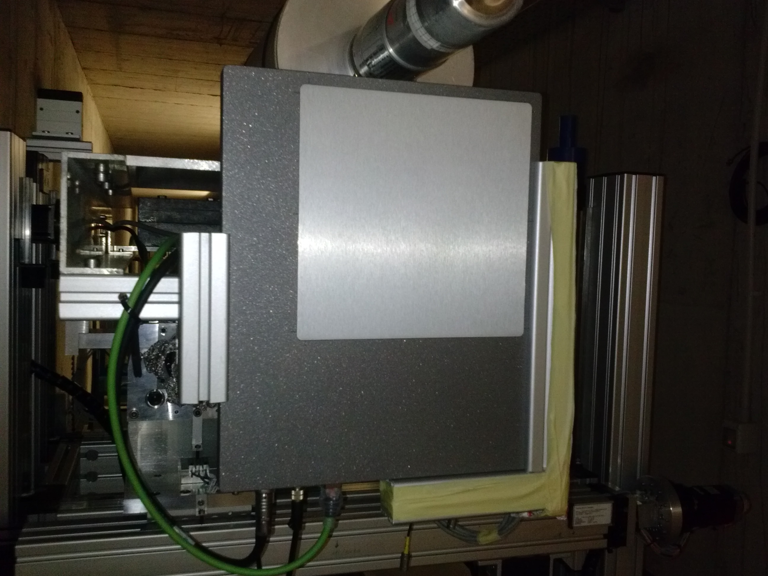
Two detectors have been used in the test campaign (Fig. 13). For spectral analysis a portable High Purity Germanium Spectrometer (HPGe, resolution 500 eV 80 keV; 550 eV 122 keV) with a liquid nitrogen cooling system is available (left panel). A digital X-ray detector with a total collecting area of 20 20 cm2 was used to acquire the diffracted images (right panel). The imager consists of a 800 m thick CsI panel, directly deposited on a Si sensor operating as a two-dimensional photodiode array of 1024 1024 elements, providing a spatial resolution of 200 m. Each frame has a maximum integration time of 17 seconds but multiple frames can be summed off-line in order to increase the total exposure time and the image quality.
7 Test results
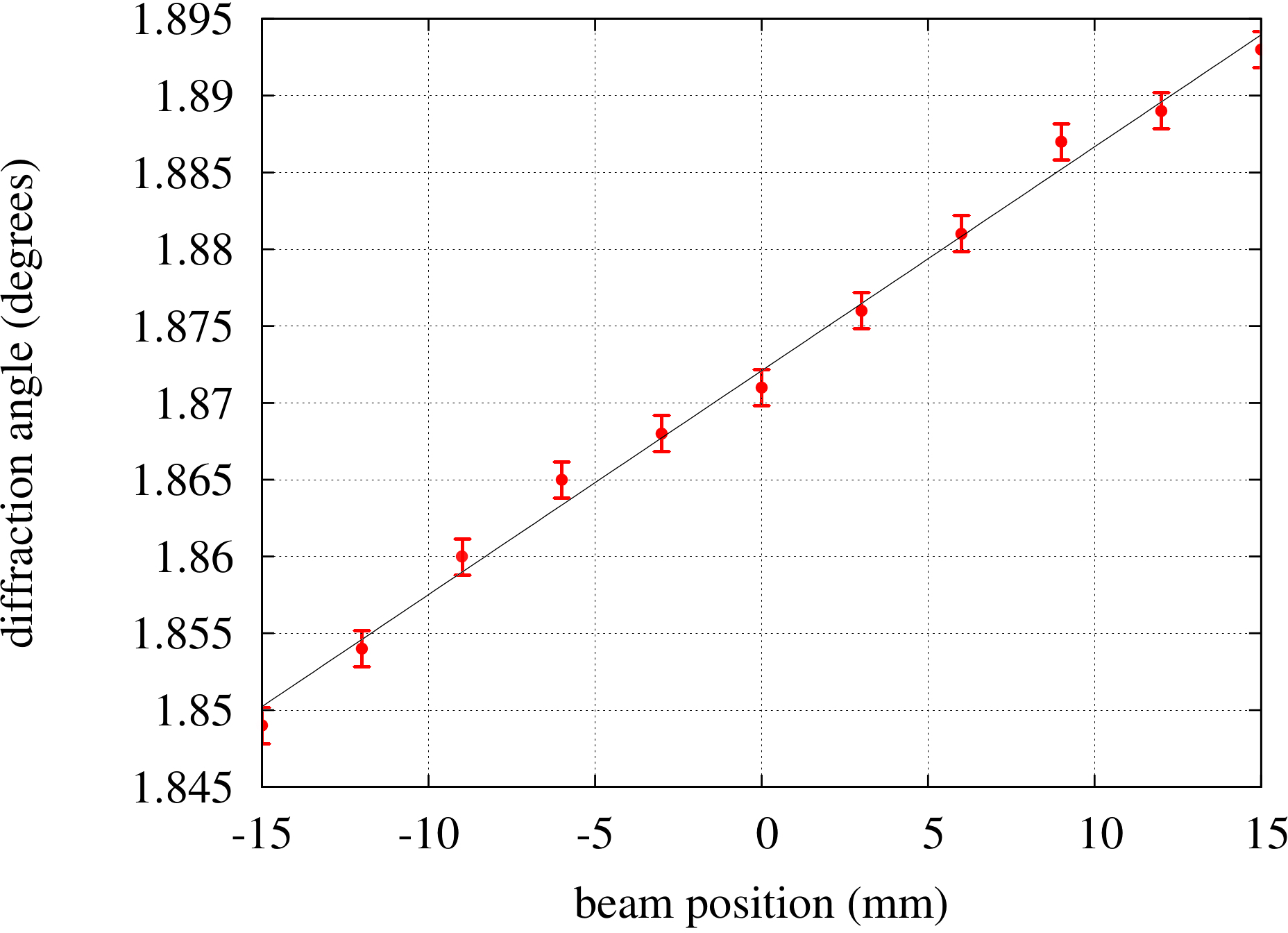
The crystals provided by cnr/imem - Parma have been characterized in terms of efficiency and focusing effect before being mounted on the support of the Laue lens. The presented tests were performed with one crystal sample of the received batch. The curvature radius of the crystal was estimated through the X-ray fluorescence line of the X-ray tube anode available in the facility (Tungsten K = 59.2 keV) with the method already described in Liccardo2014 and it gives a value of = 39.41.5 m (see Fig. 14).
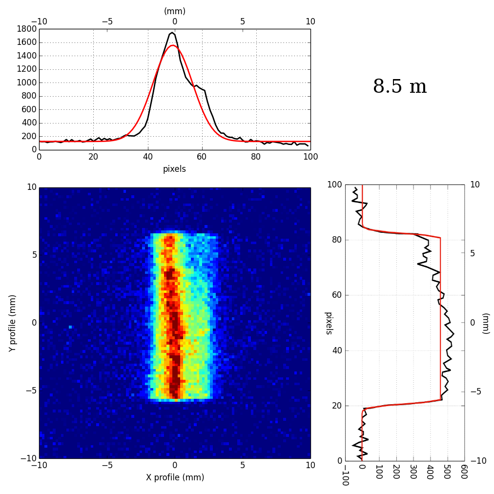
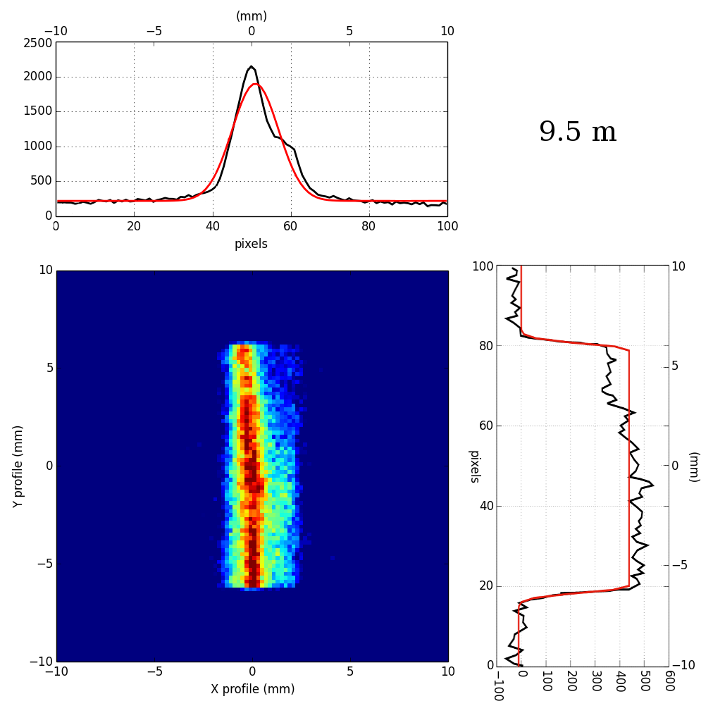
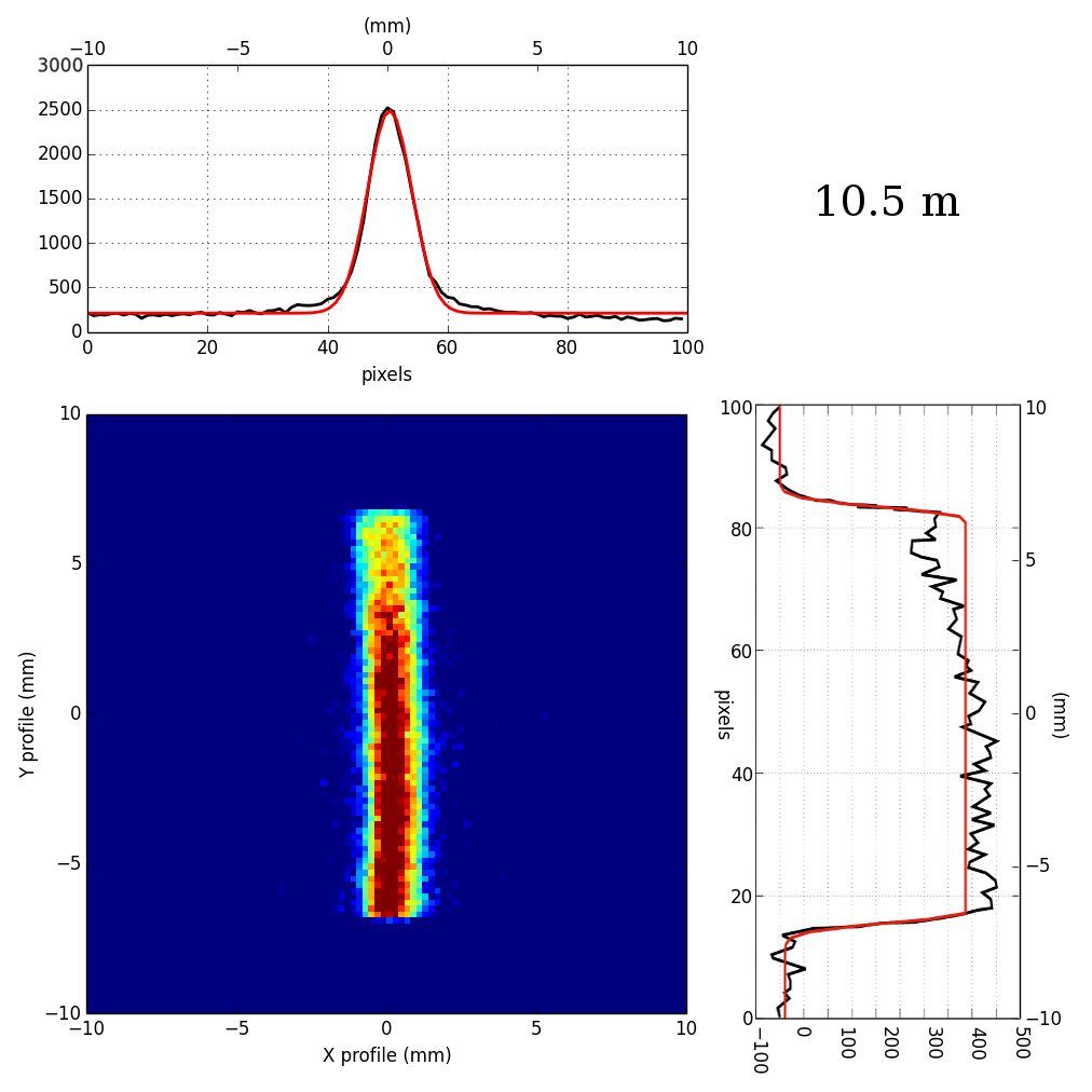
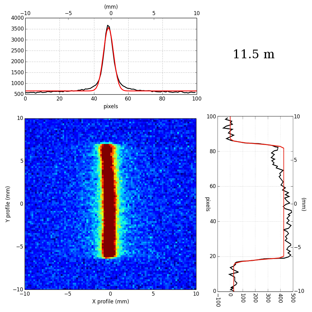
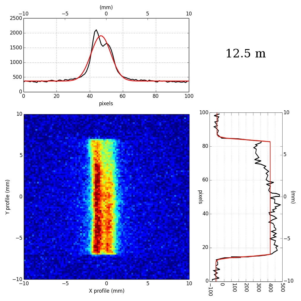
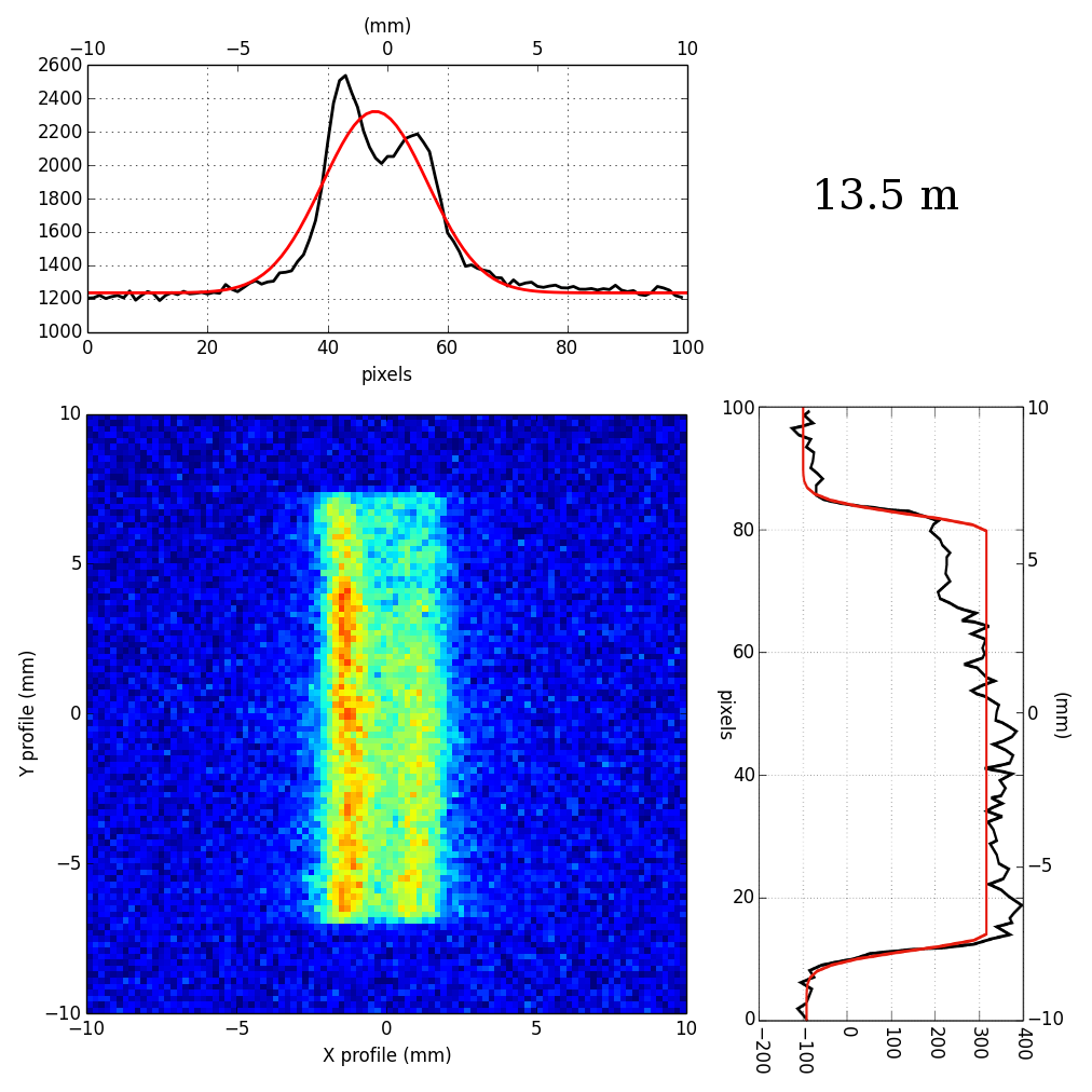
To test the described focusing effect, the beam size on the crystals was set to 20 10 mm2, the longer size in the x coordinate, in order to better demonstrate the focusing effect along that direction. The image of the diffracted signal was studied with a total exposure time of 510 seconds. For comparison with the Monte Carlo simulations, the detector was progressively set at the same distances reported in Sec. 4 (8.5, 9.5, 10.5, 11.5, 12.5, 13.5 m). The results are shown in Fig. 15, where it is evident that the different distance between crystal and detector results in a changing of both image shape and dimensions. The analysis of the x and y profile for each image of the diffracted beam acquired at different distances are also shown. As along the x profile the focusing effect of the GaAs mosaic crystal is present, it can be satisfactory described with a Gaussian function, plus a constant that represents the background counts which have not been subtracted. The function adequately fit the data, mainly at distances close to the nominal distance = 11.40 m, while the fit becomes poor far from the nominal position (e.g. at 8.5 m or 13.5 m). This discordance between fit and data is caused by a not uniform curvature of the specific sample along its axis, which is emphasized particularly out of focus. The y profile was instead modeled with the convolution of a box function with a Gaussian and the width of the curve was measured at half of the peak value. In Tab. 1 the best fit values of the measured fwhm are reported and compared with those obtained from the Monte Carlo calculations (see Sec.5).
| Experimental data | Monte Carlo | |||
| Crystal-detector | x fwhm | y fwhm(a) | x fwhm | y fwhm |
| distance (m) | (mm) | (mm) | (mm) | (mm) |
| 8.5 | 4.950.21 | 12.330.32 | 4.450.07 | 13.160.10 |
| 9.5 | 3.110.25 | 12.470.25 | 3.300.07 | 13.500.10 |
| 10.5 | 1.850.23 | 13.210.34 | 2.250.07 | 14.010.12 |
| 11.5 | 1.370.29 | 13.470.29 | 1.350.08 | 14.350.10 |
| 12.5 | 2.290.24 | 13.930.43 | 2.110.08 | 14.700.09 |
| 13.5 | 3.120.24 | 14.310.32 | 3.260.07 | 15.210.10 |
| 14.5 | 4.630.21 | 14.700.20 | 4.750.07 | 15.460.10 |
(a) the fwhm of the rectangular function is taken at half of the peak value of the curve.
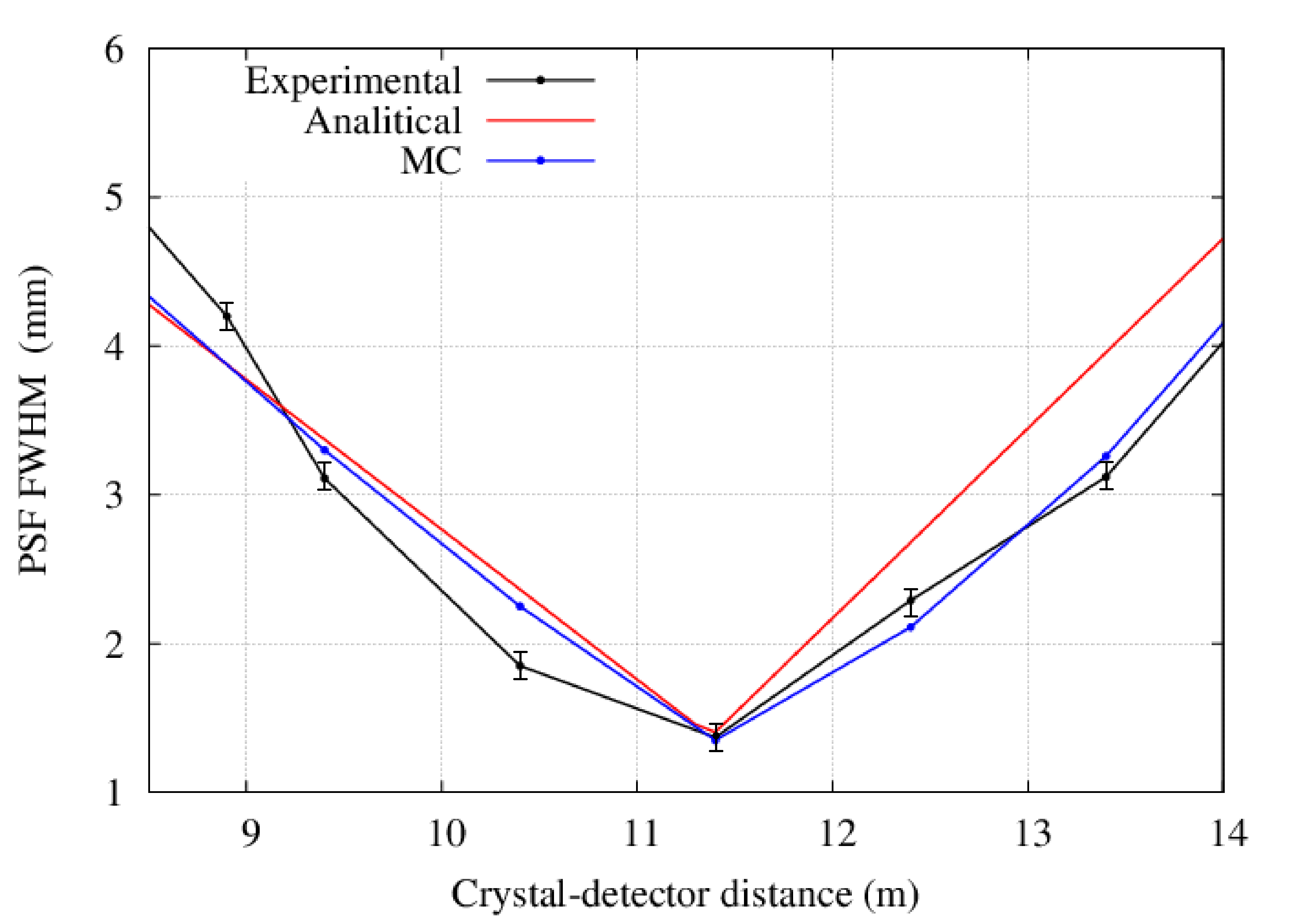
Along the x direction, where the focusing effect is expected, we found a good agreement between experimental and Monte Carlo results. Along the y coordinate, no focusing effect is expected and the diffracted beam suffers a lengthening which is mainly due to the divergence of the beam. It is worth noting that the psf in the y direction broadens with the increase of the distance from the crystal. The agreement between experimental data and Monte Carlo is shown in Fig. 16 where also the results based on the analytical calculations of Sec. 3 have been reported. Within the uncertainties, the agreement is satisfactory.
8 Conclusions
In this paper, a real focusing effect from a bent crystal of Gallium Arsenide (220) has been shown and discussed. The sample, provided by cnr/imem - Parma, was part of a batch of crystals bent by a lapping procedure. The requested curvature can be reproduced with a good precision (5% uncertainty). For the laue project a large number of tiles made of GaAs (220) and Ge (111) are being mounted on a lens petal frame, in order to build for the first time a Laue lens petal capable of operating over a broad energy band ( 90-300 keV). A systematic analysis of the diffracted profiles has been presented, using a Monte Carlo ray tracer with a set of tools capable of describing the focusing effect for both a parallel beam and a diverging beam. Both the cases of flat crystals and bent crystals with 40 m curvature radius have been investigated. All the processes of building and testing a Laue lens are made on ground while the lens is conceived for astrophysical applications. For this reason a detailed study of the behavior in the case of a finite distance between the radiation source and the crystals cannot be avoided. The good agreement found between experimental tests and Monte Carlo results give us the confidence needed about the correctness of the Monte Carlo calculations also for the case of a parallel beam from an astrophysical source, that is the final goal of the laue project.
Acknowledgements.
The laue team wish to tanks the Italian Space Agency for the financial support under the contract I/068/09/0.References
- (1) T. R. Lindquist and W. R. Webber, “A focusing X-ray telescope for use in the study of extraterrestrial X-ray sources in the energy range 20-140 keV,” Canadian Journal of Physics Supplement, vol. 46, p. 1103, 1968.
- (2) R. K. Smither, P. B. Fernandez, T. Graber, P. von Ballmoos, J. Naya, F. Albernhe, G. Vedrenne, and M. Faiz, “Review of Crystal Diffraction and Its Application to Focusing Energetic Gamma Rays,” Experimental Astronomy, vol. 6, pp. 47–56, Dec. 1995.
- (3) H. Halloin, P. von Ballmoos, J. Evrard, G. K. Skinner, J. M. Alvarez, M. Hernanz, N. Abrosimov, P. Bastie, B. Hamelin, P. Jean, J. Knödlseder, R. K. Smither, and G. Vedrenne, “Gamma-Ray Astronomy Starts to see CLAIRE: First Light for a Crystal Diffraction Telescope,” in 5th INTEGRAL Workshop on the INTEGRAL Universe (V. Schoenfelder, G. Lichti, and C. Winkler, eds.), vol. 552 of ESA Special Publication, p. 739, Oct. 2004.
- (4) F. Frontera, G. Loffredo, A. Pisa, L. Milani, F. Nobili, N. Auricchio, V. Carassiti, F. Evangelisti, L. Landi, S. Squerzanti, K. H. Andersen, P. Courtois, L. Amati, E. Caroli, G. Landini, S. Silvestri, J. B. Stephen, J. M. Poulsen, B. Negri, and G. Pareschi, “Development status of a Laue lens project for gamma-ray astronomy,” in Proceedings of the SPIE, vol. 6688, Sept. 2007.
- (5) E. Virgilli, F. Frontera, V. Valsan, V. Liccardo, V. Carassiti, F. Evangelisti, and S. Squerzanti, “Laue lenses for hard x-/soft -rays: new prototype results,” in Proceedings of the SPIE, vol. 8147, id. 81471B 9 pp., 2011.
- (6) W. H. Zachariasen, Theory of X-ray Diffraction in Crystals. Wiley, 1945.
- (7) N. Lund, “An “ESA-Affordable” Laue-lens,” Experimental Astronomy, vol. 20, pp. 211–217, Dec. 2005.
- (8) Malgrange, “X-ray propagation in distorted crystals: From dynamical to kinematical theory,” Crystal Research and Technology, vol. 37, 2002.
- (9) C. Ferrari, E. Buffagni, E. Bonnini, and D. Korytar, “Curved focusing crystals for hard X-ray astronomy,” Crystallography Reports, vol. 58, pp. 1058–1062, Dec. 2013.
- (10) R. K. Smither, K. A. Saleem, D. E. Roa, M. A. Beno, P. von Ballmoos, and G. K. Skinner, “High diffraction efficiency, broadband, diffraction crystals for use in crystal diffraction lenses,” Experimental Astronomy, vol. 20, pp. 201–210, Dec. 2005.
- (11) S. Keitel, C. Malgrange, T. Niemöller, and J. R. Schneider, “Diffraction of 100 to 200 keV X-rays from an Si1-xGex gradient crystal: comparison with results from dynamical theory,” Acta Crystallographica Section A, vol. 55, pp. 855–863, 1999.
- (12) H. Kawata, M. Sato, and Y. Higashi, “Improvements on water-cooled and doubly bent crystal monochromator for compton scattering experiments,” Nucl. Instrum. Meth. A, vol. 467-468, pp. 404–408, 2001.
- (13) V. Bellucci, R. Camattari, V. Guidi, I. Neri, and N. Barrière, “Self-standing bent silicon crystals for very high efficiency Laue lens,” Experimental Astronomy, vol. 31, pp. 45–58, Aug. 2011.
- (14) R. Camattari, E. Dolcini, V. Bellucci, A. Mazzolari, and V. Guidi, “High diffraction efficiency with hard X-rays through a thick silicon crystal bent by carbon fiber deposition,” Journal of Applied Crystallography, vol. 47, pp. 1762–1764, Oct 2014.
- (15) E. Buffagni, C. Ferrari, F. Rossi, L. Marchini, and A. Zappettini, “Preparation of bent crystals as high-efficiency optical elements for hard x-ray astronomy,” Optical Engineering, vol. 51, p. 056501, May 2012.
- (16) E. Virgilli, F. Frontera, V. Valsan, V. Liccardo, V. Carassiti, S. Squerzanti, M. Statera, M. Parise, S. Chiozzi, F. Evangelisti, E. Caroli, J. Stephen, N. Auricchio, S. Silvestri, A. Basili, F. Cassese, L. Recanatesi, V. Guidi, V. Bellucci, R. Camattari, C. Ferrari, A. Zappettini, E. Buffagni, E. Bonnini, M. Pecora, S. Mottini, and B. Negri, “The laue project and its main results,” in Proceedings of the SPIE, vol. 8861, id. 886106 17 pp., 2013.
- (17) C. Ferrari, E. Buffagni, E. Bonnini, and A. Zappettini, “X-ray diffraction efficiency of bent GaAs mosaic crystals for the laue project,” Optical Engineering, vol. 53, p. 047104, Apr. 2014.
- (18) E. Buffagni, E. Bonnini, C. Ferrari, E. Virgilli, and F. Frontera, “X-ray characterization of curved crystals for hard x-ray astronomy,” in Society of Photo-Optical Instrumentation Engineers (SPIE) Conference Series, vol. 9510 of Society of Photo-Optical Instrumentation Engineers (SPIE) Conference Series, p. 6, May 2015.
- (19) R. Camattari, V. Guidi, and I. Neri, “Quasi-mosaicity as a tool for focusing hard x-rays,” in Society of Photo-Optical Instrumentation Engineers (SPIE) Conference Series, vol. 8443 of Society of Photo-Optical Instrumentation Engineers (SPIE) Conference Series, p. 35, Sept. 2012.
- (20) V. Liccardo, E. Virgilli, F. Frontera, and V. Valsan, “Characterization of bent crystals for laue lenses,” in Society of Photo-Optical Instrumentation Engineers (SPIE) Conference Series, vol. 8443, 2012.
- (21) G. Loffredo, C. Pelliciari, F. Frontera, V. Carassiti, S. Chiozzi, F. Evangelisti, L. Landi, M. Melchiorri, S. Squerzanti, S. Brandt, C. Budtz-Joergensen, S. Laursen, N. Lund, J. Polny, and N. J. Westergaard, “X-ray facility for the ground calibration of the X-ray monitor JEM-X on board INTEGRAL,” vol. 411, pp. L239–L242, Nov. 2003.
- (22) E.Virgilli, the larix facility, 2015. http://larixfacility.unife.it.
- (23) E. Virgilli, V. Liccardo, V. Valsan, F. Frontera, E. Caroli, J. Stephen, F. Cassese, L. Recanatesi, and M. Pecora, “The laue project for broad band gamma-ray focusing lenses,” in Optics for EUV, X-Ray, and Gamma-Ray Astronomy V, vol. 8147, 2011.
- (24) V. Liccardo, E. Virgilli, F. Frontera, V. Valsan, E. Buffagni, C. Ferrari, E. Bonnini, A. Zappettini, V. Guidi, V. Bellucci, and R. Camattari, “Study and characterization of bent crystals for Laue lenses,” Experimental Astronomy, vol. 38, pp. 401–416, Dec. 2014.