On the Degrees of Freedom of the Symmetric Multi-Relay MIMO Y Channel
Abstract
In this paper, we study the degrees of freedom (DoF) of the symmetric multi-relay multiple-input multiple-output (MIMO) Y channel, where three user nodes, each with antennas, communicate via geographically separated relay nodes, each with antennas. For this model, we establish a general DoF achievability framework based on linear precoding and post-processing methods. The framework poses a nonlinear problem with respect to user precoders, user post-processors and relay precoders. To solve this problem, we adopt an uplink-downlink asymmetric strategy, where the user precoders are designed for signal alignment and the user post-processors are used for interference neutralization. With the user precoder and post-processor designs fixed as such, the original problem then reduces to a problem of relay precoder design. To address the solvability of the system, we propose a general method for solving matrix equations. Together with the techniques of antenna disablement and symbol extension, an achievable DoF of the considered model is derived for an arbitrary setup of . We show that for , the optimal DoF is achieved for . We also show that the uplink-downlink asymmetric design proposed in this paper considerably outperforms the conventional approach based on uplink-downlink symmetry.
Index Terms:
Multiway relay channel, MIMO, network coding, signal alignment, symbol extensionI Introduction
Various wireless relaying techniques have been extensively studied for decades due to their capability to extend the coverage and enhance the capacity of wireless networks [1, 2, 3, 4]. In particular, two-way relaying based on physical-layer network coding (PNC) has attracted much research interest in the past decade [4, 5, 7, 6, 8]. In the two-way relay channel, two users exchange information via a single relay node. Compared with conventional one-way relaying, PNC potentially doubles the spectral efficiency by allowing a relay node to decode and forward message combinations rather than individual messages. Later, the idea of PNC was extended to support efficient communications over multiway relay channels (mRC) [9], where multiple users exchange data with the help of a single relay. Efficient PNC design has been studied for various data exchange models, including pairwise data exchange [10, 11], full data exchange [10, 12], and clustered pairwise/full data exchange [10, 14, 13, 15]. Multiple-input multiple-output (MIMO) techniques have also been incorporated into PNC-aided relay networks to achieve spatial multiplexing [16].
The capacity of the MIMO mRC generally remains a challenging open problem [17, 18]. Existing work [19, 20, 21, 22, 23, 24, 25, 26] was mostly focused on analyzing the degrees of freedom (DoF) that characterizes the capacity slope at high signal-to-noise ratio (SNR). Various signaling techniques have been developed to intelligently manipulate signals and interference based on the ideas of PNC and interference alignment [27]. Particularly, the authors in [22, 23, 24] studied the DoF of the MIMO Y channel, where three users exchange data in a pairwise manner with the help of a single relay. To derive the DoF of this model, a key difficulty is how to jointly optimize the linear processors, including the precoders at the user transmitters, the precoder at the relay, and the post-processers at user receivers. This problem was elegantly solved in [23] by optimal design of the signal space seen at the relay, where the user precoders and post-processors are constructed by pairwise signal alignment and uplink-downlink symmetry, and the relay precoder by appropriate orthogonal projections. Similar ideas have also been used to derive the DoF of other multiway relay models [13, 17].
In the work on MIMO mRC mentioned above, a major limitation is that a single relay node is employed to serve multiple user nodes simultaneously. This implies that the relay node is usually the performance bottleneck of the overall network [13, 15]. As such, some recent work began to explore the potential of deploying more relay nodes for enhancing the network capacity. For instance, the authors in [28] derived an achievable DoF of the two-relay MIMO mRC in which two pairs of users exchange messages in a pairwise manner via two relays. Later, the work in [29] improved the DoF result in [28] by using the techniques of pairwise signal alignment and uplink-downlink symmetric design. The extension to the case of more than two user pairs was also considered in [29]. However, the DoF characterization of the multi-relay MIMO mRC is still at a very initial stage. The reason is twofold. First, for a multi-relay mRC, the relays are geographically separated and hence cannot jointly process their received signals. This implies that manipulating the relay signal space is far more difficult than that in the single-relay case. Although some of the existing techniques for single-relay mRCs can be directly borrowed for signaling design in a multi-relay mRC, the efficiency of these techniques is no longer guaranteed. Second, for given user precoders and post-processors, the solvability problem for a MIMO mRC (with single or multiple relays) can be converted to a linear system with certain rank constraints. A substantial difference between the single-relay and multiple-relay MIMO mRCs is that the linear system for the multi-relay involves multiple matrix variables, and so solving the corresponding achievability problem is much more challenging. For example, the MIMO multipair two-way relay channel with two relay nodes was considered in [29]. The achievability proof therein relies on some recent progresses on the solvability of linear matrix systems, and is difficult to be extended to the case with more than two relays or to other multi-relay mRCs.
In this paper, we analyze the DoF of the symmetric multi-relay MIMO Y channel, where three user nodes, each with antennas, communicate with each other via relay nodes, each with antennas. Compared with the MIMO Y channel in [22], a critical difference is that our new model contains an arbitrary number of relays, rather than only a single relay. Following [29], we formulate a general DoF achievability problem for the multi-relay MIMO Y channel based on linear processing techniques, involving the design of user precoders, relay precoders, and user post-processors. The main contributions of this paper are as follows.
-
•
In contrast to the conventional uplink-downlink symmetric design which is widely used in single-relay MIMO mRCs, we propose a new uplink-downlink asymmetric approach to solve the DoF achievability problem of the symmetric multi-relay MIMO Y channel. Specifically, in our approach, only user precoders are designed based on signal space alignment; the user post-processors are designed directly for interference neutralization. Furthermore, we show that under certain conditions, the uplink-downlink asymmetry allows the relays to deactivate a portion of receiving (not transmitting) antennas to facilitate the signal space alignment at relays. This implies that under certain conditions, some of the receiving antennas at the relays are redundant to achieve the derived DoF.
-
•
Given the designed user precoders and post-processors, the original problem boils down to a linear system on the relay precoders with certain rank constraints. Due to the presence of multiple relays, the linear system involves multiple matrix variables. To tackle the solvability of this system, we establish a new technique to solve linear matrix equations with rank constraints. We emphasize that this technique can potentially be used to analyze the DoF of other multi-relay MIMO mRCs with various data exchange models, e.g., pairwise data exchange [11] and clustered full data exchange [14, 13, 15].
-
•
Based on the above new techniques, we derive an achievable DoF of the symmetric multi-relay MIMO Y channel with an arbitrary configuration of . Our achievable DoF is considerably higher than that derived by the conventional uplink-downlink symmetric approach. Also, a DoF upper bound is presented by assuming full cooperation among the relays and treating the multiple relays together as a single large relay. We establish the optimality of our achievable DoF for by showing that the achieved DoF matches the upper bound.
Notation: We use bold upper and lower case letters for matrices and column vectors, respectively. denotes the dimensional complex space. and represent the zero matrix and the -dimensional identity matrix, respectively. For any matrix , denotes the vectorization of formed by stacking the columns of into a single column vector. Moreover, represents the Kronecker product operation.
II System Model
II-A Channel Model
Consider a symmetric multi-relay MIMO Y channel as shown in Fig. 1, where three user nodes, each equipped with antennas, exchange information with the help of relay nodes, each with antennas. Pairwise data exchange is employed, i.e., every user delivers two independent messages, one to each of the other two users. We assume that the information delivering is half-duplex, i.e., nodes in the network cannot transmit and receive signals simultaneously in a single frequency band. Every round of data exchange consists of two phases, namely, the uplink phase and the downlink phase. The two phases have equal duration , where is an integer representing the number of symbols within each phase interval.
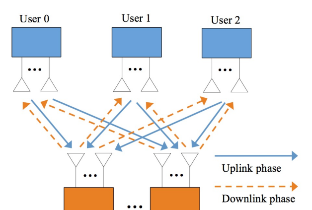
In the uplink phase, the users transmit signals to the relays simultaneously. The received signal at each relay is written by
| (1) |
where denotes the channel matrix from user to relay ; is the transmitted signal of user ; is the received signal at relay ; is the additive white Gaussian noise (AWGN) matrix at relay , with the entries independently drawn from . Note that is the noise power at relay . The power constraint for user is , where is the maximum transmission power allowed at user .
In the downlink phase, the relays broadcast signals to the users. The received signal at each user is represented by
| (2) |
where is the channel matrix from relay to user ; is the transmitted signal from relay ; is the received signal at user ; is the AWGN matrix at user , with entries independently drawn from . Here, is the noise power at user . The power constraint of relay is given by , where is the power budget of relay .
The entries of channel matrices and are drawn from a continuous distribution, implying that the channel matrices are of full column or row rank, whichever is smaller, with probability one. We assume that channel state information (CSI) is globally known at every node in the model, following the convention in [16, 10, 17, 11, 12, 13, 14, 15].111To realize the scheme in this paper, global CSI is sufficient but not necessary for every node. Each node only needs to know its linear processor designed in this scheme. There are many ways to achieve this. For example, we can employ a central controller that collects global CSI, computes the linear processors of the nodes, and then transmits the linear processors to their corresponding nodes. This will reduce to some extent the system overhead of global CSI acquisition at every node, without compromising the DoF. Moreover, for notational convenience, we interpret the user index by modulo 3, e.g., user 3 is the same as user 0.
II-B Degrees of Freedom
The goal of this paper is to analyze the degrees of freedom of the symmetric multi-relay MIMO Y channel described above. For convenience of discussion, we assume the same power constraint at each node, i.e., and , which will not compromise the generality of the DoF results derived in this paper. Let be the message from user to , where is the corresponding information rate, for and . Note that is in general a function of power , denoted by . An information rate is said to be achievable if the error probability of decoding message at receiver approaches zero as . An achievable DoF of user to user is defined as
| (3) |
Intuitively, can be interpreted as the number of independent spatial data streams that user can reliably transmit to user during each round of data exchange. An achievable total DoF of the symmetric multi-relay MIMO Y channel is defined as
| (4) |
Note that the factor in (4) is due to half-duplex communication. The optimal total DoF of the considered model, denoted by , is defined as the supremum of . In this paper, we assume a symmetric DoF setting with for any , . Then the total achievable DoF can be represented by .
We now present a DoF upper bound by assuming full cooperation among the relays. Under this assumption, the system model in (1) and (2) reduces to a single-relay MIMO Y channel, with antennas at the relay. Therefore, the optimal DoF of such a single-relay MIMO Y channel naturally serves as a DoF upper bound of the model considered in (1) and (2). From [23], this upper bound is given by
| (5) |
Note that the optimal DoF in [23] is derived for full-duplex communication. Thus the upper bound in (5) is scaled by a factor of due to the half-duplex loss.
II-C Linear Processing
In this paper, an achievable DoF of the symmetric multi-relay MIMO Y channel is derived by linear processing techniques. The message , , is encoded into , with independent spatial streams in channel uses. The transmitted signal of user is given by
| (6) |
where is the linear precoding matrix for . An amplify-and-forward scheme is employed at the relays. Specifically, the transmitted signal of each relay is represented by
| (7) |
where is the precoding matrix of relay .
With (1), (6), and (7), we can express the received signal of user in (2) as
| (8) |
In the above, consists of four signal components: the desired signal, the self interference, the other interference and the noise. Since user perfectly knows the CSI and the self message , the self-interference term in (II-C) can be pre-cancelled before further processing. Each user is required to decode spatial streams, from each of the other two users. To this end, there must be an interference-free subspace with dimension in the receiving signal space of user . More specifically, denote by a projection matrix, with being the projected image of in the subspace spanned by the row space of . Then, to ensure the decodability of at user , we should appropriately design , , and to satisfy two sets of requirements, as detailed below.
First, should be free of interference. That is, the following interference neutralization requirements should be met:
| (9a) | ||||
| (9b) | ||||
| (9c) | ||||
| Here, “interference neutralization” refers to a special transceiver design strategy for interference cancellation such that a common source of interference from different paths cancels itself at a destination. Second, user needs to decode spatial streams from the projected signal . To ensure the decodability, the desired signal in (II-C) after projection should be of rank . Define | ||||
| Then represents the effective channel for the messages desired by user . To ensure the decodability of spatial streams at each user , we have the following rank requirements: | ||||
| (9d) | ||||
Given an antenna setup and a target DoF , if there exist suitable satisfying (9) for randomly generated channel matrices with probability one, then a total DoF is achieved by the proposed linear processing scheme. Thus, the key issue is to analyze the solvability of the system (9) with respect to , which is the main focus of the rest of this paper.
III Achievable DoF of the Symmetric Multi-Relay MIMO Y Channel
In general, to check the achievability of a certain DoF , we need to jointly design the matrices to meet (9). This is a challenging task since the equations in (9) are nonlinear with respect to . To tackle this problem, we start with a conventional approach based on the idea of uplink-downlink symmetry.
III-A Conventional Approach with Uplink-Downlink Symmetry
Uplink-downlink symmetry has been widely used in precoding design for MIMO mRCs [17, 15, 22, 23, 29]. It is shown to be optimal for many single-relay MIMO mRCs [17, 22, 23], and efficient for some multi-relay MIMO mRCs [29]. In this subsection, we follow the idea of uplink-downlink symmetry to solve (9). Then, for an arbitrary configuration of , we derive an achievable DoF (or an upper bound of the achievable DoF) of the symmetric multi-relay MIMO Y channel. We show that there is a significant DoF gap between this result and the DoF upper bound in (5), implying the inadequacy of the uplink-downlink symmetric precoding design for multi-relay MIMO mRCs.
To start with, we split each projection matrix equally into two parts as
| (10) |
where is the projection matrix for the message . Then the interference neutralization conditions (9a)-(9c) can be rewritten as
| (11) |
Note that for all the 3 users, there are 12 matrix equations in (11) for interference neutralization. Moreover, the rank requirements remain the same as (9d).
We next establish DoF points, namely, and , , by following uplink-downlink symmetric design. The DoF point is achievable, while the points , , are just upper bounds. That is, for any , , the total DoF achieved by the uplink-downlink symmetric design is upper bounded as .
The first DoF point is derived by deactivating of the relays. In this case, the model reduces to a single-relay MIMO Y channel with the antenna number of the relay equal to . Then, the precoding design in [23] can be applied directly. From the result of [23], a total DoF of can be achieved for half-duplex single-relay MIMO Y channel with . That is, is achievable.
We now consider the DoF point . Note that the remaining DoF points can be straightforwardly obtained by deactivating relays, for . Following [29], we apply signal alignment techniques for the design of to reduce the number of linearly independent constraints in (15). First consider the uplink signal alignment design. We align the signals exchanged by user and user at each relay. That is, we design to satisfy
| (12) |
Note that for the single-relay case, it usually suffices to align and in a common subspace. However, for the multi-relay case here, we rely on a more strict constraint (12) for signal alignment, so as to reduce the number of linearly independent equations in (15). We then consider the downlink signal alignment. From (11), we see that the uplink equivalent channel matrix is of the same size as the transpose of downlink equivalent channel matrix , for . This structural symmetry implies that any beamforming design in the uplink phase directly carries over to the downlink phase. Specifically, we design the downlink receiving matrices to satisfy
| (13) |
From the rank-nullity theorem, to ensure the existence of full-rank satisfying (12) and (13), the following conditions must be met:
| (14) |
With (12) and (13), the interference neutralization conditions in (11) reduces to
| (15) |
Note that are already fixed to meet (12) and (13). Thus (15) is a linear system of with equations and unknown variables. The system has a non-zero solution of provided . Together with (14), we obtain the DoF point . Note that by deactivating relays, we immediately obtain the remaining DoF points , for .
We now apply the antenna disablement lemma [20] to the above DoF points, yielding a continuous DoF curve of uplink-downlink symmetric design for an arbitrary value of :
| (16) |
where and the -function is defined as
| (17) |
It is worth noting that the DoF in (16) is not necessarily achievable. To verify its achievability, we still need to check whether the solution of to (15) satisfies the rank requirements (9d). In general, the DoF in (16) serves as an upper bound for the DoF achieved by the uplink-downlink symmetric design described in this subsection. In fact, this bound is enough to illustrate the limitation of the uplink-downlink symmetric design. Specifically, we compare (16) with the upper bound in (5). We see that for a sufficiently large (say, ), in (16) is proportional to while the DoF upper-bound in (5) and the achievable DoF derived in this paper (Theorem 1 in Section III-B) both increase linearly with . This DoF gap implies the inefficiency of the uplink-downlink symmetric design.
III-B Main Result
We now propose a new and more efficient approach to the precoding design for the symmetric multi-relay MIMO Y channel, so as to achieve a higher DoF than the result in (16). The novelty of our approach is as follows. First, instead of following the conventional uplink-downlink symmetry, our approach performs signal alignment only in the uplink phase. This means that, in the design of user precoding and post-processing, only are designed to align signals to reduce the number of linearly independent equations in (9a)-(9c); the post-processors are used directly for the purpose of neutralizing interference, rather than designed by following the uplink-downlink symmetry. This introduces additional freedom for system design. Further, to exploit the advantage of this uplink-downlink asymmetric design, we allow a certain number of receiving (but not transmitting) antennas at each relay to be deactivated. With this treatment, signal alignment can be performed in a larger range of . With the above design of and , the problem reduces to the design of the relay precoders that satisfy the linear system in (9a)-(9c) and the rank requirements in (9d). We then establish a general method to address this solvability problem. We emphasis that this method can be used to analyze the solvability of any linear system with rank constraints, and so, will find applications to the DoF analysis of many other multiway relay networks.
The main result of this paper is presented below, with the proof given in Section IV.
Theorem 1.
For the symmetric multi-relay MIMO Y channel, any total DoF is achievable, where
| (18) |
Corollary 1.
For , any total DoF is achievable, where
| (19) |
Proof.
By setting , Corollary 1 follows directly from Theorem 1. ∎
Remark 1.
For , the result in Theorem 1 is given piecewisely in the following corollaries.
Corollary 2.
For , any total DoF is achievable, where
| (20) |
Proof.
By setting , the result in (20) follows from Theorem 1. ∎
Remark 2.
We see that for , the achievable total DoF in Theorem 1 is given by the minimum of four terms: , , , and . Note that the DoF and are achieved by two different signal alignment approaches, while the DoF is achieved without signal alignment. The achievability of the DoF and is derived by the technique of antenna disablement.
Corollary 3.
For and , the optimal total DoF of the symmetric multi-relay MIMO Y channel is given by
| (21) |
Proof.
For , the achievable total DoF in Corollary 2 coincides with the upper bound (5), and therefore the optimal total DoF is achieved. ∎
Remark 3.
For (with ), our achievable total DoF does not match the upper bound in (5). We conjecture that the upper bound obtained by assuming full cooperation among the relays is loose in general. Tighter DoF upper bounds can be derived by characterizing the DoF degradation due to distributed relaying. This will be an interesting topic for future research.
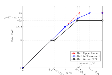
Fig. 2 and Fig. 3 illustrate the achievable total DoF in Corollary 2 with and , respectively, together with the DoF in (16) and the DoF upper bound in (5). We see that our approach significantly outperforms the conventional approach based on the uplink-downlink symmetric design. Particularly, as , the corresponding gap increases unboundedly. For , our achievable total DoF coincides with the DoF upper bound given in (5), indicating that the optimal total DoF of the considered model is achieved. However, for the uplink-downlink symmetric design, the optimal total DoF is achieved only for . We also see that for sufficiently large , there is a constant gap between the achievable total DoF of conventional approach and that of our approach, implying that the uplink-downlink symmetric approach can not make full use of all the relay antennas.
We now study the asymptotic behavior of the achievable total DoF as goes to infinity. It is readily seen from Corollary 2 that, for large and any fixed , the achievable total DoF increases linearly in . What is more interesting is to understand the asymptotic DoF behavior by studying the achievable total DoF normalized by the total number of relay antennas, i.e., , where . This limiting process illustrates how the degree of cooperation among relay antennas affects the DoF of the system. We have the following asymptotic bound.
Corollary 4.
For the symmetric multi-relay MIMO Y channel, as and go to infinity at the same rate, the asymptotic bound of is given by
| (22) |
Proof.

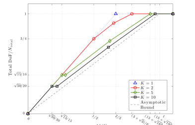
In Fig. 4, we compare the achievable total DoF (normalized by ) with respect to for different values of . Our target is to see the impact on the achievable total DoF when a single -antenna relay is split into relay nodes. Fig. 4 illustrates the normalized achievable DoF for and . Note that the case of assumes that all the antennas at the relay can cooperate, and so serves as an upper bound of the normalized achievable DoF. From Fig. 4, we see that as increases, for a given , the normalized achievable DoF monotonically decreases and approaches the asymptotic bound in Corollary 4.
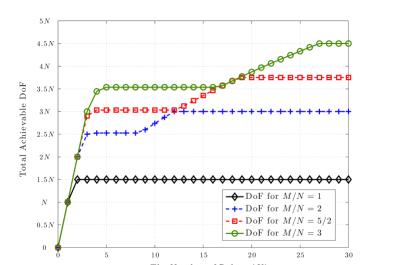
Fig. 5 plots the achievable total DoF versus the number of relays for various values of . Clearly, cannot exceed , the case in which all the user antennas are fully utilized. So, for a fixed value of , it is interesting to explore how the achievable DoF increases with respect to and the number of relay nodes required to achieve . From Fig. 5, we see that the achievable total DoF is roughly a piecewise linear function with respect to . The minimum numbers of relays required to achieve are for , respectively. Fig. 5 also shows that, if a certain amount of inefficiency can be tolerated in utilizing user antennas, then the required number of relays can be considerably reduced. For example, only 5 relays are required to achieve for , while the number is 27 in achieving . It is also worth noting that there are transitional flat DoF curves for the cases of , and 3. This flatness corresponds to the result (that is independent of ).
IV Proof of Theorem 1
This section is dedicated to the proof of Theorem 1. For , Theorem 1 has been proven in [22]. Thus, it suffices to only consider the case of . Based on the linear processing techniques in Section II-B, our goal is to jointly design to satisfy condition (9). We propose two types of signal alignment methods for to generate redundant equations in (9a)-(9c), as detailed below.
IV-A Signal Alignment I
Signal Alignment I is described as follows. For , and are aligned to satisfy
| (24) |
or equivalently
| (25a) | |||
| where | |||
| (25e) | |||
From the rank-nullity theorem, there exist full-rank and satisfying (25a) with probability one, provided
| (26) |
With (24), we see that in (9a)-(9c), the three equations on the left are identical to the three equations on the right respectively. Ignoring the redundant equations, we rewrite (9a)-(9c) as
| (27a) | |||
| For completeness, we repeat (9d) as follows: | |||
| (27b) | |||
What remains is to determine the value of to ensure the existence of and satisfying (27).
IV-B Achievable DoF for Signal Alignment I
Based on the proposed signal alignment in (24), for user , the other interference term in (II-C) is rewritten as
| (28) |
spanning a subspace of -dimension. To neutralize the above interference at every user, we first design to neutralize a portion of the interference, and then design to null the remaining part. Specifically, we split the beamforming matrix as
| (29) |
where and with defined as
| (30) |
We design to neutralize the interference corresponding to for each user. That is, need to satisfy
| (31) |
With (31), the received signal at user in (II-C) still contains a -dimensional desired signal and the -dimensional interference corresponding to . With in (30), we have , implying that the antennas at each user are already fully utilized. Thus, the rank requirement (27b) can be alternatively represented by
| (32) |
We design to null the remaining interference corresponding to for each user. Specifically, we require to satisfy
| (33) |
Note that the left null space of has at least dimensions. Therefore, there always exists with full row rank satisfying (33).
We now show that the above and satisfy (27). We start with (27a) for :
| (34a) | ||||
| (34b) | ||||
| (34c) | ||||
where (34b) and (34c) follow from (31) and (33), respectively. Similarly, condition (27a) also holds for . We then consider (27b) with and obtain
| (35a) | ||||
| (35b) | ||||
where (35a) follows from (33); (35b) is due to the fact that is of full rank from (32). Similarly, (27b) also holds for .
Consequently, to prove that a certain point is achievable for Signal Alignment I, it suffices to show that there exist and satisfying (24), (31), and (32). We have the following lemma:
Proof.
See Appendix I-A. ∎
Note that the DoF in Lemma 1 is not necessarily an integer. A frequently used technique to achieve a rational DoF is symbol extension in which an extended MIMO system is constructed with multiple channel uses. The details can be found in Appendix II.
IV-C Signal Alignment II
The derivation in the preceding subsection is based on the signal alignment (24). However, this alignment imposes the requirement of (26) that may not always be met. In this subsection, we generalize the signal alignment in (24) by allowing the signal to be aligned in a subspace of the receiving signal space seen at each relay. Note that for Signal Alignment I in (24), the full received signal space at each relay is considered in aligning signals. For Signal Alignment II described below, we will only consider the projection of user signals into a subspace of the signal space at each relay. This will relax the signal alignment constraint in (26) at the cost of certain loss of freedom for each relay to process its received signal.
Let
| (36) |
be the dimension of the subspace for signal alignment. Of course, should be chosen to ensure . Then, each relay deactivates antennas for signal reception, with the number of active antennas intact for broadcasting. That is, the number of active antennas of each relay is in the uplink phase and in the downlink phase. This implies that the proposed uplink-downlink precoding design is asymmetric in nature.
A convenient way to select a subspace of dimension is to deactivate the last antennas at each relay. Then the precoding matrix of each relay can be decomposed as
| (37) |
where and . By the deactivation, the effective channel matrix from user to relay is and the processing matrix of relay becomes . As analogous to (24), we aim to design satisfying
| (38) |
or equivalently
| (39a) | |||
| where | |||
| (39e) | |||
Since by the definition of in (36), there exist full-rank matrices and satisfying (38) with probability one.
IV-D Achievable DoF for Signal Alignment II
We now consider the construction of to satisfy (40). Similarly to Signal Alignment I, are designed to neutralize the interference corresponding to , while are designed to null the remaining interference corresponding to . More specifically, as analogous to (31) and (32), we require to satisfy
| (42a) | ||||
| (42b) | ||||
Moreover, is of full row rank and satisfies
| (43) |
It can be readily shown that, with in (30) and in (36), there always exist satisfying (43). Thus, to prove the achievability of a certain DoF point , it suffices to show that there exist satisfying (42). We have the following result.
Proof.
See Appendix I-B. ∎
IV-E Achievable DoF with No Signal Alignment
From Lemmas 1 and 2, we see that both Signal Alignment I and II cannot be realized when is relatively small. We next focus on relatively small values of and show that (or equivalently, ) is achievable for . To start with, we set
| (44) |
We see that, (9a)-(9c) reduce to a linear system of with unknown variables and equations. The system allows non-zero solutions of provided , i.e., . To prove the achievability of , it suffices to show that there exist satisfying all the conditions in (9). We have the following result.
Proof.
See Appendix I-C. ∎
IV-F Achievable DoF Using Antenna Disablement
In the preceding subsections, we have established an achievable DoF for . We now follow the antenna disablement approach [20] to establish the achievable DoF for other ranges of . Specifically, for , we disable antennas at each relay. Then, from Lemma 2, we see that any DoF can be achieved, where is the number of active antennas at each relay. The only issue is that may be not an integer. This issue can be solved by the technique of symbol extension described in Appendix II. Similarly, with symbol extension and antenna disablement, is achievable for .
V Conclusion and Future Work
In this paper, we developed a new formalism to analyze the achievable DoF of the symmetric multi-relay MIMO Y channel. Specifically, we adopted the idea of uplink-downlink asymmetric design and proposed a new method to tackle the solvability problem of linear systems with rank constraints. In the proposed design, we also incorporated the techniques of signal alignment, antenna disablement, and symbol extension. An achievable DoF for an arbitrary configuration of was derived.
The study of multi-relay MIMO mRCs is still in an initial stage. Based on our work, the following directions will be of interest for future research.
V-A Tighter Upper Bounds
For , our achievable total DoF does not match the full relay-cooperation upper bound in (5). We conjecture that the main reason for this mismatch is that the upper bound is too loose in this range of . As such, tighter upper bounds are highly desirable to fully characterize the DoF of the symmetric multi-relay MIMO Y channel. This, however, requires careful analysis on the fundamental performance degradation caused by the separation of relays.
V-B General Antenna and DoF Setups
In this paper, we considered the symmetric multi-relay MIMO Y channel, where the numbers of antennas of all user nodes are assumed to be the same. We also assumed a symmetric DoF setting, where each user transmits the same number of independent spatial data streams. The main purpose of these assumptions is to avoid the combinatorial complexity in manipulating signals and interference. The techniques used in this paper can be extended to the cases with asymmetric antenna and DoF setups. However, this results in a DoF achievability problem far more complicated than (9), since we need to analyze the feasibility of all possible DoF tuples of under an asymmetric antenna configuration. The optimal DoF region for the single-relay case has been recently reported in [30]. We believe that the techniques used in [30] will provide some insights on deriving the DoF region of the multi-relay case.
V-C Cases with More Users
Our approach can be extended to multi-relay MIMO Y channels with more than three users. However, we emphasize that such an extension is not trivial. As seen from [12, 13, 14, 15], for MIMO mRCs with more than three users, more signal alignment patterns than pairwise alignment should be exploited to support efficient data exchanges. This implies that in multi-relay MIMO Y channels with more than three users, we need to combine our uplink-downlink asymmetric approach with more intelligent signal alignment strategies. Therefore, the extension to multi-relay MIMO Y channels with more users will be an interesting research topic worthy of future effort.
Appendix A Proof of Lemmas 1-3
A-A Proof of Lemma 1
We need to prove that for and , there exist and satisfying (24), (31), and (32) with probability one. The main steps of the proof are presented as follows:
- •
-
•
For and in the given ranges, construct a set of channel realizations such that a randomly generated channel realization belongs to with probability one.
-
•
Prove that for almost all elements in , there exist and satisfying (24), (31), and (32). 222Although the term “satisfying (24)” appears both here and in (54), the conditions are different. In (54), we require that there exist satisfying (24) and , while here we require that there exist and satisfying (24), (31), and (32). It is possible that for some channel realization, there exist satisfying (24), but there do not exist , together with these , satisfying (31) and (32).
We first show that the signal alignment (24) can be performed. For , we have
| (46) |
Further, as , we obtain
| (47) |
Therefore, (26) is met, and so there exist full-column-rank satisfying (24) with probability one.
We next show that in (30) is well-defined. That is, holds for chosen sufficiently close to . For , together with and , we obtain
| (48) |
where the last step holds by noting for . On the other hand, as
| (49) |
we can always choose close to to ensure . We henceforth always assume that is appropriately chosen such that .
We now consider step 2 of the proof. Denote the overall channel of the symmetric multi-relay MIMO Y channel by
| (50) |
where
| (51) |
Then, we rewrite (31) using Kronecker product as
| (52) |
where
| (53a) | |||
| (53b) |
We are now ready to define the set . For and , define
| (54) |
where is defined in (25e). We claim that a randomly generated belongs to with probability one. Recall that the entries of are drawn independently from a continuous distribution. Since is a wide matrix, it is of full row rank () with probability one. We next show that for a random and full-column-rank satisfying (24), in (53a) is of full row rank with probability one. To see this, we first note that is a wide matrix since
| (55) |
Second, from the channel randomness, we have and . Then is of rank . Each block-row of consists of submatrices in the form of . From the channel randomness, the rank of each block-row is given by , since . Further, by noting that the three block-rows of are statistically independent of each other, we conclude that is of full row rank () with probability one.
We now consider the last step, i.e., to show that for almost all in , there exist and satisfying (24), (31), and (32). To proceed, we present a useful lemma below.
Lemma 4.
Proof.
Consider a random . By the definition of , there exist satisfying (24) and . Using Gaussian elimination, the general solution of (52) can be written by
| (56) |
where are free variables with , and , , span the right null space of . Recall that Gaussian elimination involves the following arithmetic operations: addition, subtraction, multiplication and division. This implies that each entry of is a rational function of the entries of and . Thus, with proper scaling, we can always express each entry of as a finite-degree polynomial of the entries of and . Following similar arguments, since are designed to satisfy and each is of full row rank, entries of matrices can be represented by polynomials of the entries of and , where are free variables with . This implies that each entry of satisfying (52) can be represented by a finite-degree polynomial of the entries of , , and . Recall that (52) is the Kronecker product form of (31) and consists of the vectorizations of . Therefore, entries of satisfying (31) can be represented by finite-degree polynomials of the entries of , , and .
Now consider the following determinant product:
| (57) |
Note that if and only if the matrix is of full rank for , or equivalently, (32) holds. Therefore, to prove Lemma 4, it suffices to show that for a random , there exist and satisfying (24) and , such that with probability one.
To this end, we first note that is a finite-degree polynomial with respect to entries of , , and , i.e., can be represented by
| (58) |
where is a finite integer, is a polynomial of the entries of , and is a monomial of , . Note that for . By assumption, there exist and satisfying (24), (31), and (32), implying that there exist , , and such that . Thus, is a non-zero polynomial. Let be the index set such that , , is a non-zero polynomial. Denote by the solution set of the polynomial system: , . From algebraic geometry, has Lebesgue measure zero in . That is, for a random generated , the probability of is zero. Thus, for a random , there is at least one , and in (58) is a non-zero polynomial of and with probability one. Therefore, we can always find and such that . That is, there exist and satisfying (24), (31), and (32), which concludes the proof of Lemma 4. ∎
To invoke Lemma 4, we need to show the existence of a certain , , and satisfying (24), (31), and (32). To this end, we set for , and choose and to be random matrices with the entries independently drawn from a continuous distribution. Then, we choose full-rank matrices to satisfy
| (63) |
It can be verified that for , . Then
| (64) |
implying that the null space of the matrix in (63) has at least dimensions. Thus full-column-rank satisfying (63) exist with probability one. Based on the chosen and , we can readily determine the values of and (not necessarily unique). With , are also determined. Finally, is determined by . It can be verified that the constructed belongs to with probability one.
We now show that the above constructed , , and satisfy (24), (31), and (32) with probability one. First, by construction, (24) is automatically met. Further, as , condition (31) reduces to (63) which holds again by construction. Thus (31) holds. To check (32), it suffices to consider the case due to symmetry. Note that are determined by and , which only depend on and . That is, are not functions of . Moreover, both and are independent of . Therefore,
| (65) |
with probability one, where the first equality follows from , , and , while the second equality follows by noting that for . Moreover, as , we obtain
| (66) |
with probability one, and so (32) is met.
A-B Proof of Lemma 2
The proof of Lemma 2 closely follows that of Lemma 1. The main steps of the proof are presented as follows:
- •
-
•
For and , construct a set such that a randomly generated channel realization belongs to with probability one.
- •
We first show that the signal alignment in (38) can be performed for and . From the discussion in Section IV-C, it suffices to show that is well defined. That is, for close to , defined in (36) satisfies . Too see this, note that
| (67) |
implying that for any . Further, for , we have
| (68) |
Therefore, we can always choose close to to ensure . As analogous to Appendix A, we can also verify that for , we can choose close to such that .
We now consider step 2 of the proof. For and , define
| (69) |
where is defined in (39e) and
| (73) |
where as defined in Section IV-C. Similarly to Appendix A-A, we can verify that a random generated belongs to with probability one.
We now consider the last step of the proof, i.e., to show that for almost all in , there exist and satisfying (38) and (42). As analogous to Lemma 4, we have the following result. Note that the proof of Lemma 5 follows that of Lemma 4 step by step, and is omitted for brevity.
Lemma 5.
Based on Lemma 5, to show that for almost all there exist and satisfying (38) and (42), it suffices to find a certain that satisfies the condition. To this end, we set
| (74) |
and randomly generate , with the entries independently drawn from a continuous distribution. Then, we choose full-rank matrices to satisfy
| (79) |
With in (74), is simply the first columns of . For and , we have
| (80) |
implying that the null space of the matrix in (79) has at least dimensions. Thus full-rank exist with probability one. Based on the chosen and , we determine the values of and (not necessarily unique). With , are also determined. Finally, is determined by and it can be verified that with probability one.
We now show that the above constructed , , and satisfy (38) and (42) with probability one. By construction, (38) is automatically met. Further, from (79), we see that (42a) holds with probability one. To check (42b), it suffices to consider the case by symmetry. Note that are determined by and , which only depend on and . That is, are not functions of . Moreover, , , and are independent of each other by construction. Therefore,
| (81) |
As , we obtain
| (82) |
with probability one, and so (42b) is met. We complete the proof of Lemma 2.
A-C Proof of Lemma 3
As analogous to the arguments in Appendix I-A, the general solution of (9a)-(9c) with respect to can be represented by finite-degree polynomials of the entries of . Then similar to Lemma 4, we have the following lemma for the solvability of (9). Note that to ease the notation, we do not define the set , but rephrase its constraints as conditions in the lemma. We omit the proof for brevity.
Lemma 6.
Based on Lemma 6, what remains is to construct and satisfying (9) and . We basically follow the construction in the proof of Lemma 1. Let , for , and be random matrices with entries independently drawn from a continuous distribution. Then we design with full column rank satisfying
| (94) |
where are constructed in (44). From the rank-nullity theorem, there exist full-column-rank satisfying (94) with probability one, provided , (which is true for ). Note that from (44), and are the left columns and the right columns of , respectively. Thus, we can combine them together to form with full column rank. It can be readily verified that, together with and in (44), the above constructed and satisfy (9a)-(9c). Moreover, since are randomly generated, (9d) and are met with probability one, which concludes the proof of Lemma 3.
Appendix B Symbol Extension
With the techniques of symbol extension and antenna disablement, we show that all the results in Section IV hold for any rational DoF . We focus on Signal Alignment I in Section IV-B. The treatments for other signal alignment approaches are similar. Let satisfying . Further, assume that both and are rational numbers satisfying . Let be a positive integer such that both and are integers. Then, we extend the channel by times and disable antennas at each user end. With some abuse of notation, we represent the extended channel of each link in a block-diagonal form as
| (95a) | ||||
| (95b) | ||||
where and are the uplink and downlink channel matrices in the -th channel use respectively, with
Our goal is to show that any DoF with is achievable for the extended channel, implying that an average DoF is achieved per channel use. To this end, we need to design and to satisfy condition (9) (with the rank in (9d) replaced by ). This can be done by performing Signal Alignment I and following the arguments in Appendix I-A step by step, with the only main difference being that and take the block diagonal forms in (95a), which does not change our conclusion. We omit the details for brevity.
References
- [1] T. Cover and A. E. Gamal, “Capacity theorems for the relay channel,” IEEE Trans. Inf. Theory, vol. 25, no. 5, pp. 572-584, Jan. 2003.
- [2] G. Kramer, M. Gastpar, and P. Gupta, “Cooperative strategies and capacity theorems for relay networks,” IEEE Trans. Inf. Theory, vol. 51, no. 9, pp. 3037-3063, Sep. 2005.
- [3] Editors: Y. Hua, D. W. Bliss, S. Gazor, Y. Rong, and Y. Sung, “Theories and methods for advanced wireless relays: Issue I,” IEEE J. Sel. Areas Commun., vol. 30, no. 8, pp. 1361-1367, Sept. 2012.
- [4] S. Zhang, S. C. Liew, and P. P. Lam, “Hot topic: Physical-layer network coding,” in Proc. ACM MobiCom’06, Los Angeles, USA, Sep. 2006.
- [5] W. Nam, S. Y. Chung, and Y. H. Lee, “Capacity of the Gaussian two-way relay channel to within 1/2 bit,” IEEE Trans. Inf. Theory, vol. 56, no. 11, pp. 5488-5495, Nov. 2010.
- [6] T. Cui, F. Gao, T. Ho, and A. Nallanathan, “Distributed space-time coding for two-way wireless relay networks,” IEEE Trans. Signal Processing, vol. 57, no. 2, pp. 658-671, Feb. 2009.
- [7] R. Rankov and A. Witneben, “Achievable rate regions for the two-way relay channel,” in Proc. IEEE ISIT, Seattle, USA, July 2006.
- [8] F. Gao, R. Zhang, and Y.-C. Liang, “Optimal channel estimation and training design for two-way relay networks,” IEEE Trans. Commun., vol. 57, no. 10, pp. 3024-3033, Oct. 2009.
- [9] D. Gündüz, A. Yener, A. Goldsmith, and H. V. Poor, “The multiway relay channel,” IEEE Trans. Inf. Theory, vol. 59, no. 1, pp. 51-63, Jan. 2013.
- [10] K. Liu, M. Tao, Z. Xiang, and X. Long, “Generalized signal alignment: On the achievable DoF for multi-user MIMO two-way relay channels,” IEEE Trans. Inf. Theory, vol. 61, no. 6, pp. 3365-3386, June 2015.
- [11] Z. Xiang, M. Tao, J. Mo, and X. Wang, “Degrees of freedom for MIMO two-way X relay channel,” IEEE Trans. on Signal Process., vol. 61, no. 7, pp. 1711-1720, July 2013.
- [12] B. Yuan, X. Liao, F. Gao, and X. Luo, “Achievable degrees of freedom of the four-user MIMO Y channel,” IEEE Commun. Lett., vol. 18, no. 1, pp. 6-9, Jan. 2014.
- [13] R. Wang, X. Yuan, and M. Tao, “Degrees of freedom of MIMO multiway relay channel with clustered pairwise exchange,” IEEE J. Select. Area. Comm., vol. 33, no. 2, pp. 337-351, Dec. 2014.
- [14] Y. Tian and A. Yener, “Degrees of freedom for the MIMO multi-way relay channel,” IEEE Trans. Inf. Theory, vol. 60, no. 5, pp. 2495-2511, May 2014.
- [15] X. Yuan, “MIMO multiway relaying with clustered full data exchange: Signal space alignment and degrees of freedom,” IEEE Trans. Wireless Commun., vol. 13, no. 12, pp. 6795-6808, May 2015.
- [16] X. Yuan, T. Yang, and I. B. Collings, “Multiple-input multiple-output two-way relaying: A space-division approach,” IEEE Trans. Inf. Theory, vol. 59, no. 10, pp. 6421-6440, Oct. 2013.
- [17] C. Wang, “Beyond one-way communication: Degrees of freedom of multiway relay MIMO interference networks,” IEEE Trans. Inf. Theory, vol. 15, no. 10, pp. 7174-7186, Oct. 2016.
- [18] A. Chaaban, A. Sezgin, and A. S. Avestimehr, “Approximate sum-capacity of the Y-channel,” IEEE Trans. Inf. Theory, vol. 59, no. 9, pp. 5723-5740, Sept. 2013.
- [19] N. Lee and R. W. Heath, “Degrees of freedom for the two-cell two-hop MIMO interference channel: Interference-free relay transmission and spectrally efficient relaying protocol,” IEEE Trans. Inf. Theory, vol. 59, no. 5, pp. 2882-2896, May 2013.
- [20] S. Chen and R. S. Cheng, “On the achievable degrees of freedom of a -user MIMO interference channel with a MIMO relay,” IEEE Trans. Wireless Commun., vol. 12, no. 8, pp. 4118-4128, Aug. 2013.
- [21] R. Wang and X. Yuan, “MIMO multiway relaying with pairwise data exchange: A degrees of freedom perspective,” IEEE Trans. on Signal Process., vol. 62, no. 20, pp., 5294-5307, July 2014.
- [22] N. Lee, J. B. Lim, and J. Chun, “Degrees of freedom of the MIMO Y channel: Signal space alignment for network coding”, IEEE Trans. Inf. Theory, vol. 56, no. 7, pp. 3332-3342, July 2010.
- [23] A. Chaaban, K. Ochs, and A. Sezgin, “The degrees of freedom of the MIMO Y-channel,” in Proc. IEEE ISIT, Istanbul, Turkey, July 2013.
- [24] A. A. Zewail, M. Nafie, Y. Mohasseb, and H. El-Gamal, “Achievable degrees of freedom region of MIMO relay networks using detour schemes,” in Proc. of IEEE Int. Conf. Commun. (ICC), Sydney, Australia, 2014.
- [25] A. Chaaban and Aydin Sezgin, “Cyclic communication and the inseparability of MIMO multi-way relay channels,” IEEE Trans. Inf. Theory, vol. 61, no. 12, pp. 6734-6750, Dec. 2015.
- [26] Z. Cheng, N. Devroye, and T. Liu, “The degrees of freedom of full-duplex bi-directional interference networks with and without a MIMO Relay,” IEEE Trans. Wireless Commun., vol. 15, no. 4, pp. 2912-2924, April 2016.
- [27] V. R. Cadambe and S. A. Jafar, “Interference alignment and degrees of freedom of the -user interference channel,” IEEE Trans. Inf. Theory, vol. 54, no. 8, pp. 3425-3441, Aug. 2008.
- [28] K. Lee, N. Lee, and I. Lee, “Achievable degrees of freedom on MIMO two-way relay interference channels,” IEEE Trans. Wireless Commun., vol. 12, no. 4, pp. 1472-1480, April 2013.
- [29] R. Wang, X. Yuan, and R. W. Yeung, “MIMO multipair two-way relaying with distributed relays: Joint signal alignment and interference neutralization,” IEEE Trans. Inf. Theory, vol. 62, no. 3, pp. 1326-1343, March 2016.
- [30] K. Liu, X. Yuan, and M. Tao, “Optimal degrees of freedom region for the asymmetric MIMO Y channel,” IEEE Commun. Lett., vol. 20, no. 12, pp. 2454-2457, Dec. 2016.
- [31] T. Ding, X. Yuan, and S. C. Liew, “Degrees of freedom of MIMO Y channel with multiple relays,” in Proc. IEEE ISIT, Barcelona, Spain, July 2016.