Visibility of Young’s interference fringes: Scattered light from small ion crystals
Abstract
We observe interference in the light scattered from trapped 40Ca+ ion crystals. By varying the intensity of the excitation laser, we study the influence of elastic and inelastic scattering on the visibility of the fringe pattern and discriminate its effect from that of the ion temperature and wave-packet localization. In this way we determine the complex degree of coherence and the mutual coherence of light fields produced by individual atoms. We obtain interference fringes from crystals consisting of two, three and four ions in a harmonic trap. Control of the trapping potential allows for the adjustment of the interatomic distances and thus the formation of linear arrays of atoms serving as a regular grating of microscopic scatterers.
pacs:
37.10.Ty, 37.10.Vz, 42.50.CtThe seminal double slit experiment by Young Shamos (1959) is one of the most prominent experiments in physics. Originally, it formed the basis for understanding that light is a wave giving rise to phenomena like interference and diffraction, whereas in its modern interpretation it displays in a compact form the notion of wave-particle duality Dirac (1989).
The original Young experiment employed transversally coherent light using a small aperture placed in front of the light source (in fact the sun Shamos (1959)). This results in electromagnetic waves at the two slits oscillating in phase and a visibility of the fringe pattern . The use of laser-driven atoms as “slits” enables the formation of more complex light fields, ranging from fully coherent to partially coherent and even fully incoherent fields. This transition arises from the fundamental process of photon scattering by the atoms. In the quantum theory of light Loudon (2000); Cohen-Tannoudji et al. (2004); Scully and Zubairy (1997) the scattering event involves the destruction of an incoming photon and the creation of an outgoing photon. For low intensities the elastic process dominates such that the outgoing photon has the same frequency and a fixed phase relationship with the incoming one Diedrich and Walther (1987); Eschner et al. (2001). Interferences in this regime have been observed in a seminal experiment by Wineland and coworkers involving two mercury atoms trapped in an ion trap and only weakly excited by a near-resonant laser Eichmann et al. (1993) (see also Itano et al. (1998); Ficek and Swain (2005); DeVoe and Brewer (1996); Wong et al. (1997); Skornia et al. (2001); Schön and Beige (2001)).
However, when increasing the intensity of the laser, the atomic emitters undergo internal dynamics which may alter the emitted photon frequency and phase. Such inelastic scattering processes lead to a reduced mutual coherence of the light fields, i.e., the emission of partially coherent light, resulting in a decrease of the visibility of the interference fringes. In the case of a very intense driving laser, the atoms emit fully incoherent fluorescence light Mollow (1969); in this case the visibility of the fringe pattern disappears.
Aside from the internal dynamics, the driving laser affects additionally the external degrees of freedom of the ions as the laser is used likewise for laser cooling of the particles. The ion temperature plays an important role for the fringe visibility as it determines the localization of the scatterers, i.e., of the “slits”. Since an increased laser intensity alters both the ratio of elastic to inelastic scattering as well as the localization of the atoms, the influence of inelastic scattering on the mutual coherence of the scattered light has not been observed experimentally.
In this letter we study the visibility of Young interference fringes produced by individual atoms employing a gated detection method to clearly separate the effect of inelastic scattering from that of reduced atom localization. A theoretical model to explain the measured fringe patterns is developed taking into account the multi-level structure of the atoms and the presence of a repumping laser. Experimentally, we investigate ion crystals with up to four ions in a harmonic trap potential or in specially shaped trapping fields that allow for the adjustment of the interatomic distances. In this way we are able to form linear arrays of ions serving as a regular grating of atomic scatterers.
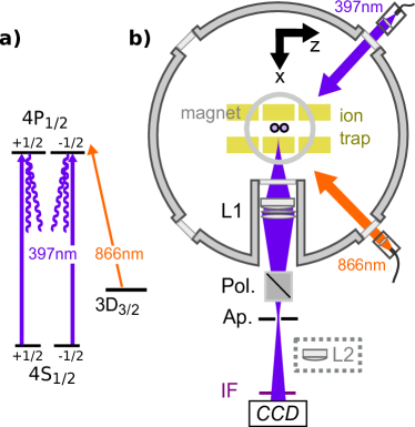
For the experiments we employ 40Ca+ ions trapped in a segmented Paul trap Jacob et al. (2014). With trap frequencies )=(1.853, 2.620, 0.977) MHz the ions form linear crystals which align along the weakest trap axis . The electric dipole transition 42S 42P1/2 of 40Ca+ near 397 nm is used for Doppler cooling and light scattering. The 42P1/2 state decays with a probability of 7% to the metastable 32D3/2 level Hettrich et al. (2015), therefore we use a laser near 866 nm for repumping to maintain continuous Doppler cooling (see Fig. 1a). The radial modes are aligned along the direction, respectively, whereas the cooling and repumping laser illuminate the ion crystals along the (x,y,z)=(1,0,-1) direction, respectively, so that the k-vectors of the laser beams have a projection on all vibrational axes of the ion crystal (see Fig. 1b).
A magnetic field of mT oriented along , generated by a permanent magnet ring placed on top of the vacuum chamber, determines the quantization axis. The laser beam near 397 nm, having a waist of about m at the ions’ positions, is linearly polarized along this axis and thus excites the transitions (see Fig. 1a). The light scattered by the ions is collected by a f/1.6 objective L1 (focal length 67 mm) at a working distance of 48.5 mm and focused at a distance of about 770 mm, after being sent through a polarization beam splitter (Pol.) oriented along , i.e., the same axis as the cooling laser (see Fig. 1b). An aperture (Ap.) (diameter 400 m) is placed at the back focal plane of the objective suppressing unwanted stray light in combination with an infrared filter (IF, center wavelenght nm). The scattered light is finally recorded by a CCD camera positioned 100 mm behind the back focal plane of the objective to observe the light in the far field, i.e., the Fourier plane of the ions. We use either an electron multiplier gain intensifier enhanced CCD camera (EMCCD, Andor iXon 860) or alternatively an intensified CCD camera (ICCD, Andor iStar 334T) with pixels (pixel size 24.5 m) and pixels (pixel size 13 m), respectively. A lens L2 (focal length f=25 mm), optionally placed in the scattered light beam behind the aperture, focuses the back focal plane onto the CCD allowing one to image and observe the ions individually, e.g. to check for the number of ions, to determine the magnification of the optical system or to adjust the axial potential.
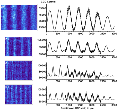
The results of the interference measurements for two, three and four ions are shown in Fig. 2. The inner parts of the CCD images ( pixels) are rotated and corrected for field distortions measured independently by observing the distance of a two-ion crystal at different positions within the field of view of the CCD. Remaining stray light and background are subtracted from the CCD images, determined by shutting off the repumping laser. The fringe patterns at the right hand side of Fig. 2 are obtained from the CCD images by integration over the vertical axis; the error bars of are deduced from photon shot noise. The fits to the interference patterns are derived from the source distribution via Fourier transformation, taking into account the resolution of the imaging device. From the fit parameters we determine the distance between the ions, the width of the point spread function (PSF), and the visibility of the interference fringes. From Fig. 2a, we obtain a distance m and a width of the PSF m for the two-ion crystal. Note, that the calculated magnification of the optical system - derived from the image of the back focal plane of L1 on the CCD by use of L2 - depends on the exact x-position of L2 which can be positioned with an accuracy of 2 mm. In view of this uncertainty we see good agreement of the determined value with the independently deduced m, based on (i) a spectroscopic determination of the COM-mode frequency of the crystal and (ii) the calculation according to James (1998).
Key for the further studies is the gated cooling probe detection (GCPD) of the scattered photons made possible by our intensifier enhanced CCD camera. The GCPD scheme works as follows (see Fig. 3): The ion crystals are initialized during 175 s via Doppler cooling under optimum conditions for the saturation and of the cooling and repumping lasers at 397 nm and 866 nm, i.e., well below the respective saturation intensities, and with a cooling and repumping laser detuning of MHz and MHz, respectively. We choose the laser detuning for the laser at 866 nm to the blue side of the resonance in order to avoid complications from dark resonances. Thereafter the saturation of the cooling laser is switched to a different value using an acousto-optical modulator. After a delay of 5 s to allow for proper switching of the laser, the CCD is gated for 10 s to observe the scattered light at 397 nm. As the motional states of the ion crystals evolve over much longer time scales (see Fig. 4), they are unable to adapt to the modified cooling laser saturation within this detection time. In this way the mutual coherence of the scattered light fields is solely determined by the internal degrees of freedom of the ions. We can thus investigate the visibility of the interference pattern as a function of the laser saturation without being affected by the ion temperature.
In the paraxial approximation and for scalar fields, i.e., for identical polarization of excitation and detection, the intensity produced by a two-ion crystal at the CCD is Mandel and Wolf (1995)
| (1) |
where () is the intensity at r if ion 2 (ion 1) is absent, denotes the real part and is the relative phase accumulated by the fields at r. In Eq. (1), corresponds to the complex degree of coherence which describes the mutual coherence of the two light fields and , generated by ion 1 at and ion 2 at , respectively. We assume identical excitation strength and thus equal intensities of the two ions. The visibility of the interference fringes is then equal to the modulus of the complex degree of coherence and the fringe modulation determined by the phase .
In a three-level model and with the ions at fixed positions, the intensity distribution on the CCD is (see Supplemental Material)
| (2) |
where denotes the single atom coherence between states s = S1/2 and p = P1/2, and is the population of the excited state decaying either to s or level d = D3/2. According to Eq. (2) the visibility of the interference pattern is given by
| (3) |
A reduction of is thus predicted for growing and reduced . If we model the ions as two-level atoms (for which Eqs. (2) and (3) equally hold) this occurs for increased laser saturation . However, the two-level model does not take into account the modification of and due to the additional decay channel to d. In this case and , and thus Eq. (3), become more involved functions of the laser parameters.
The measured produced by two-ion crystals as a function of is shown in Fig. 3. A reduction of , corresponding to the emission of partially coherent light, is observed when increasing , which agrees well with the two-level model. When the saturation of the repumping laser is increased by a factor of we observe, however, an increased visibility. This behavior is well described by the three-level model fit curves in Fig. 3 (see Supplemental Material).
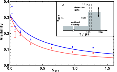
The visibilities displayed in Fig. 3 are limited by a constant prefactor of 0.3. Assuming this factor is only due to the motional excitation of the ion crystal results in a mean wavepacket size (r.m.s. of breathing and rocking modes) of 96(5) nm Itano et al. (1998). This is, however, about a factor 2.3 larger than that expected for the Doppler cooling limit, calculated for the given trap frequencies and unsaturated cooling; we measured a mean wavepacket size of 42(11) nm using sideband spectroscopy Häffner et al. (2008). We suspect therefore that the prefactor is also affected by misalignment of the quantization axis.
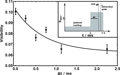
The GCPD scheme can also be employed to investigate the modification of the fringe visibility due to vibrational excitations in the ion crystal. Again, we initialize the crystal by Doppler cooling under optimum conditions (s, s). The laser saturation is then rapidly increased by a factor of while keeping the detuning unchanged. Here the CCD is gated to observe the scattered photons in a time interval of 250 s while we shift the beginning of this time interval from ms to 2.5 ms (see inset of Fig. 4). As the crystal is exposed to a higher saturation, the Doppler cooling limit and the mean phonon number in the breathing and rocking modes increases Eichmann et al. (1993). The visibility of the fringe pattern is proportional to the Debye Waller factor , where denotes the fluctuation about the equilibrium positions of ion i=1,2, is the k-vector difference of the absorbed and emitted photons and denotes the average over the thermal distributions Itano et al. (1998).
In the experiment the decrease of the fringe visibility as a function of is clearly visible (see Fig. 4), following an exponential decay with a time constant ms. The long time constant confirms our assumption that the time evolution of internal and external degrees of freedom of the ions can be separated by use of the GCPD approach. We have obtained similar data for the increase of when an initially higher crystal temperature is reduced by Doppler cooling.
Modern trap technology Brownnutt et al. (2012); Home et al. (2009), where the DC trap potential is shaped by multiple control segments, allows one to modify the trap potential along and thus the inter-ion distances. This becomes particularly relevant for crystals with ions. If a crystal with four ions is kept in a harmonic trap the equilibrium positions of the ions are non-equidistant James (1998), e.g., for trap frequencies )=(1.978, 2.180, 0.429) MHz the distance between the innermost ions is 7.2 m and between the outer and the inner ions 7.6 m, respectively. This results in an interference fringe signal with two spatial frequencies (see Fig. 2c). By adjusting the trap control electrode voltages we are able to generate a non-harmonic potential Ruster et al. (2014) such that a regular crystal with equal ion separation of 9.1 m is obtained (see Fig. 2d). The corresponding fringe pattern matches the intensity distribution of a coherently illuminated 4-slit grating.
In conclusion, we studied the mutual coherence of light fields emitted by individual atoms at the crossover from elastic to inelastic scattering. We implemented a detection scheme allowing to observe the degree of mutual coherence as a function of the saturation of the observed S P1/2 transition at fixed ion crystal temperatures. The decrease of the visibility of the interference patterns due to motional effects of the ions was investigated separately. The method could pave the way towards temperature measurements of ion crystals at low trap frequencies where standard sideband methods, highly successful in tightly confining potentials Häffner et al. (2008), become increasingly hard. We also see applications when the trap potential is adiabatically lowered Poulsen et al. (2012), e.g., when ions are loaded into optical potentials Schneider et al. (2010); Schmiegelow et al. (2016); Linnet et al. (2014). The experiment also provides opportunities to investigate multi-ion entanglement Thiel et al. (2007); Bastin et al. (2009); Moehring et al. (2007); Ritter et al. (2012); Hofmann et al. (2012); Bernien et al. (2013) or measurements of photon-photon correlations and their back action on the ion crystals Oppel et al. (2012); Gatto Monticone et al. (2014); Oppel et al. (2014).
Acknowledgements.
We gratefully acknowledge the support of LOT-QuantumDesign for lending the ICCD. We thank S.T. Dawkins for carefully reading the text. FSK and SW acknowledge the financial support of the Cluster of excellence PRISMA at the Johannes-Gutenberg Universität Mainz and the DFG within the project BESCOOL. JvZ gratefully acknowledges funding by the Erlangen Graduate School in Advanced Optical Technologies (SAOT) by the German Research Foundation (DFG) in the framework of the German excellence initiative.References
- Shamos (1959) M. H. Shamos, Great experiments in physics: firsthand accounts from Galileo to Einstein (Courier Corporation, 1959).
- Dirac (1989) P. A. M. Dirac, The Principles of Quantum Mechanics (Oxford Science Publications, 1989).
- Loudon (2000) R. Loudon, The Quantum Theory of Light (Oxford Univ. Press, 2000).
- Cohen-Tannoudji et al. (2004) C. Cohen-Tannoudji, J. Dupont-Roc, and G. Grynberg, Photons and Atoms: Introduction to Quantum Electrodynamics (Wiley-VCH, 2004).
- Scully and Zubairy (1997) M. O. Scully and M. S. Zubairy, Quantum Optics (Cambridge Univ. Press, 1997).
- Diedrich and Walther (1987) F. Diedrich and H. Walther, Phys. Rev. Lett. 58, 203 (1987).
- Eschner et al. (2001) J. Eschner, C. Raab, F. Schmidt-Kaler, and R. Blatt, Nature 413, 495 (2001).
- Eichmann et al. (1993) U. Eichmann, J. C. Bergquist, J. J. Bollinger, J. M. Gilligan, W. M. Itano, D. J. Wineland, and M. G. Raizen, Phys. Rev. Lett. 70, 2359 (1993).
- Itano et al. (1998) W. M. Itano, J. C. Bergquist, J. J. Bollinger, D. J. Wineland, U. Eichmann, and M. G. Raizen, Phys. Rev. A 57, 4176 (1998).
- Ficek and Swain (2005) Z. Ficek and S. Swain, Quantum interference and coherence: theory and experiments, Vol. 100 (Springer Science & Business Media, 2005).
- DeVoe and Brewer (1996) R. G. DeVoe and R. G. Brewer, Phys. Rev. Lett. 76, 2049 (1996).
- Wong et al. (1997) T. Wong, S. M. Tan, M. J. Collett, and D. F. Walls, Phys. Rev. A 55, 1288 (1997).
- Skornia et al. (2001) C. Skornia, J. von Zanthier, G. S. Agarwal, E. Werner, and H. Walther, Phys. Rev. A 64, 063801 (2001).
- Schön and Beige (2001) C. Schön and A. Beige, Phys. Rev. A 64, 023806 (2001).
- Mollow (1969) B. R. Mollow, Phys. Rev. 188, 1969 (1969).
- Jacob et al. (2014) G. Jacob, K. Groot-Berning, S. Wolf, S. Ulm, L. Couturier, U. G. Poschinger, F. Schmidt-Kaler, and K. Singer, arxiv.org:1405.6480 (2014).
- Hettrich et al. (2015) M. Hettrich, T. Ruster, H. Kaufmann, C. F. Roos, C. T. Schmiegelow, F. Schmidt-Kaler, and U. G. Poschinger, Phys. Rev. Lett. 115, 143003 (2015).
- James (1998) D. F. James, Appl. Phys. B: Lasers and Optics 66, 181 (1998).
- Mandel and Wolf (1995) L. Mandel and E. Wolf, Optical Coherence and Quantum Optics (Cambridge Univ. Press, 1995).
- Häffner et al. (2008) H. Häffner, C. Roos, and R. Blatt, Physics Reports 469, 155 (2008).
- Brownnutt et al. (2012) M. Brownnutt, M. Harlander, W. Hänsel, and R. Blatt, Appl. Phys. B 107, 1125 (2012).
- Home et al. (2009) J. Home, D. Hanneke, J. Jost, J. Amini, D. Leibfried, and D. Wineland, Science 325, 1227 (2009).
- Ruster et al. (2014) T. Ruster, C. Warschburger, H. Kaufmann, C. T. Schmiegelow, A. Walther, M. Hettrich, A. Pfister, V. Kaushal, F. Schmidt-Kaler, and U. G. Poschinger, Phys. Rev. A 90, 033410 (2014).
- Poulsen et al. (2012) G. Poulsen, Y. Miroshnychenko, and M. Drewsen, Phys. Rev. A 86, 051402 (2012).
- Schneider et al. (2010) C. Schneider, M. Enderlein, T. Huber, and T. Schätz, Nature Photonics 4, 772 (2010).
- Schmiegelow et al. (2016) C. T. Schmiegelow, H. Kaufmann, T. Ruster, J. Schulz, V. Kaushal, M. Hettrich, F. Schmidt-Kaler, and U. G. Poschinger, Phys. Rev. Lett. 116, 033002 (2016).
- Linnet et al. (2014) R. Linnet, I. Leroux, A. Dantan, and M. Drewsen, Appl. Phys. B 114, 295 (2014).
- Thiel et al. (2007) C. Thiel, J. von Zanthier, T. Bastin, E. Solano, and G. S. Agarwal, Phys. Rev. Lett. 99, 193602 (2007).
- Bastin et al. (2009) T. Bastin, C. Thiel, J. von Zanthier, L. Lamata, E. Solano, and G. S. Agarwal, Phys. Rev. Lett. 102, 053601 (2009).
- Moehring et al. (2007) D. L. Moehring, P. Maunz, S. Olmschenk, K. C. Younge, D. N. Matsukevich, L.-M. Duan, and C. Monroe, Nature 449, 68 (2007).
- Ritter et al. (2012) S. Ritter, C. Nolleke, C. Hahn, A. Reiserer, A. Neuzner, M. Uphoff, M. Mucke, E. Figueroa, J. Bochmann, and G. Rempe, Nature 484, 195 (2012).
- Hofmann et al. (2012) J. Hofmann, M. Krug, N. Ortegel, L. Gérard, M. Weber, W. Rosenfeld, and H. Weinfurter, Science 337, 72 (2012).
- Bernien et al. (2013) H. Bernien, B. Hensen, W. Pfaff, G. Koolstra, M. S. Blok, L. Robledo, T. H. Taminiau, M. Markham, D. J. Twitchen, L. Childress, and R. Hanson, Nature 497, 86 (2013).
- Oppel et al. (2012) S. Oppel, T. Büttner, P. Kok, and J. von Zanthier, Phys. Rev. Lett. 109, 233603 (2012).
- Gatto Monticone et al. (2014) D. Gatto Monticone, K. Katamadze, P. Traina, E. Moreva, J. Forneris, I. Ruo-Berchera, P. Olivero, I. P. Degiovanni, G. Brida, and M. Genovese, Phys. Rev. Lett. 113, 143602 (2014).
- Oppel et al. (2014) S. Oppel, R. Wiegner, G. S. Agarwal, and J. von Zanthier, Phys. Rev. Lett. 113, 263606 (2014).
- Cohen-Tannoudji et al. (1998) C. Cohen-Tannoudji, J. Dupont-Roc, and G. Grynberg, Atom-Photon Interactions: Basic Processes and Applications (Wiley-VCH, 1998).
- Agarwal (2013) G. S. Agarwal, Quantum Optics (Cambridge University Press, 2013).
I Supplemental Material: Visibility of the interference pattern
I.1 Optical Bloch equations
The interaction of an atom with laser light can be described by the optical Bloch equations Cohen-Tannoudji et al. (1998).
For a two-level system with a ground state and an excited state and an exciting laser field with Rabi frequency and detuning , they read
| (4) | ||||
where is the decay rate of the s-p-transition and .
In the three level system under investigation, there is an additional metastable state and a laser field with Rabi frequency and detuning driving the --transition. For this configuration, one obtains the following system of equations:
| (5) | ||||
where , and .
I.2 Intensity and visibility in the far field
The far field intensity of the light emitted by two coherently driven atoms is given by Agarwal (2013)
| (6) |
where , and denote the raising and lowering operators and position of atom , the wave vector of the driving laser and the direction of observation.
In the steady state, one obtains:
| (7) | ||||
with . The visibility of the interference pattern is thus given by
| (8) |
The steady state density matrix elements are obtained by setting the time derivatives to zero and solving the resulting linear system of equations. For the two level model, this yields
| (9) | ||||
where is the saturation parameter
| (10) |
This results in a visibility
| (11) |
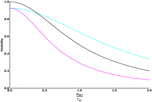
In the three level model, the expression for the visibility reads
| (12) | ||||
In Figure 1, the visibility in the three level model is shown for two different sets of laser parameters and compared to the visibility in the two level model. It can be seen that the additional decay channel towards the -state can both increase and decrease the visibility, depending on the laser parameters.