Enhanced Non-Adiabaticity in Vortex Cores due to the Emergent Hall Effect
Abstract
We present a combined theoretical and experimental study, investigating the origin of the enhanced non-adiabaticity of magnetic vortex cores. Scanning transmission X-ray microscopy is used to image the vortex core gyration dynamically to measure the non-adiabaticity with high precision, including a high confidence upper bound. Using both numerical computations and analytical derivations, we show that the large non-adiabaticity parameter observed experimentally can be explained by the presence of local spin currents arising from a texture-induced emergent Hall effect. This enhanced non-adiabaticity is only present in two- and three-dimensional magnetic textures such as vortices and skyrmions and absent in one-dimensional domain walls, in agreement with experimental observations.
The electrical control of magnetic textures through spin angular momentum transfer has attracted a massive amount of interest in the past ten years Boulle et al. (2011). As spin torque-induced magnetization manipulation exhibits favorable scaling Yamaguchi et al. (2004); Yamada et al. (2007), it underlies novel concepts to store information in non-volatile devices, such as the race-track memory Parkin et al. (2008) or the spin-transfer torque random access memory Kent and Worledge (2015). Recent progress includes the manipulation of two and three-dimensional chiral magnetic textures, known as magnetic skyrmions Jonietz et al. (2010); Woo et al. (2015), which constitute an inspiring paradigm for potential applications Fert et al. (2013). The dynamics of a magnetic texture , with Ms being the saturation magnetization, induced by spin transfer torque is usually modeled by the extended phenomenological Landau-Lifshitz-Gilbert (LLG) equation Zhang and Li (2004); Thiaville et al. (2005)
| (1) |
where the first two terms describe the damped precession of magnetization around the effective magnetic field , with denoting the gyromagnetic ratio and being the viscous Gilbert damping parameter. In the present work, refers to the damping of the homogeneous magnetic texture, which is different from the effective damping felt by the vortex core, as discussed below. The third term describes the adiabatic momentum transfer from the spin polarized conduction electrons to the local magnetization Tatara and Kohno (2004), where is the spin drift velocity and is the spin polarization of the conduction electrons. The last term () is the so-called non-adiabatic spin transfer torque, which describes the (possibly non-local) torques that do not result from the adiabatic spin transfer Zhang and Li (2004); Thiaville et al. (2005). The magnitude of the non-adiabaticity parameter and in particular the ratio determine the efficiency of the spin transfer torque for current-induced domain wall motion, as it governs for instance the domain wall velocity and thus plays a crucial role in the device performance Zhang and Li (2004); Thiaville et al. (2005). However, the physical origin and magnitude of the non-adiabaticity parameter are still under debate and an in-depth understanding of spin transport in magnetic textures is necessary to achieve efficient electrical control of the magnetization.
It has been experimentally shown that the ratio depends on the domain wall structure, transverse or vortex domain walls in soft magnetic nanostructures Kläui (2008); Heyne et al. (2010); Eltschka et al. (2010); Pollard et al. (2012), or -Bloch or Néel domain walls in materials with perpendicular magnetic anisotropy Burrowes et al. (2009). Namely, vortex walls and vortex cores in discs and rectangular elements exhibit a large non-adiabaticity Heyne et al. (2010); Eltschka et al. (2010); Pollard et al. (2012) compared to transverse domain walls Eltschka et al. (2010), albeit with some uncertainty. This large non-adiabaticity is usually attributed to mistrack between the itinerant spin momentum and the local magnetization Tatara and Kohno (2004) due to the large texture gradients present in the vortex core (radius of the vortex core ). On the other hand, the non-adiabaticity in very narrow Bloch domain walls (domain wall width of about ) in FePt nanowires is not significantly increased Burrowes et al. (2009), suggesting that spin mistracking might not be the dominant mechanism for non-adiabaticity.
In this Letter, we present a combined theoretical and experimental effort to uncover the origin of non-adiabaticity in magnetic vortex cores. Using scanning transmission X-ray microscopy to image the dynamics of a magnetic vortex core, we first measure the non-adiabaticity parameter with high precision and deduce a high confidence upper bound . Then, based on analytical and numerical considerations, we explain such an enhanced non-adiabaticity by the emergence of a local Hall effect due to the magnetic texture, an effect absent in one-dimensional domain walls.
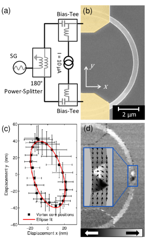
To measure the non-adiabaticity of the vortex core, we dynamically imaged the steady state gyration of the vortex core within a vortex domain wall, induced by alternating spin-polarized currents. We study vortex domain walls in a thick and wide permalloy () half-ring with a radius of , see Fig. 1(b). The half-rings were fabricated on top of a nm thick silicon nitride () membrane by electron-beam lithography, molecular beam evaporation in UHV and lift-off processing. To improve cooling, a thick aluminum nitride layer was deposited on top of the structures and on the backside of the membrane. The wires are connected by contacts, which are placed more than from the center of the nanowire [see Fig. 1(b)], to minimize in-plane Oersted fields from vertical electrical currents flowing from the contacts into the nanowire Bisig et al. (2010). At the position of the vortex wall, the in-plane field component is negligible () Bisig et al. (2010), and therefore, we can assume that the vortex gyration is purely induced by the spin transfer torque. After saturation with a magnetic field along the horizontal direction, a vortex domain wall is formed at the center of the nanowire, as shown in Fig. 1(d). Alternating currents are then injected into the nanowire with different frequencies , while measuring the sample resistance with a small direct current , to measure the microwave power within the nanowire and keep the current density constant at all frequencies Bedau et al. (2007), see Fig. 1(a). The response of the magnetization to the spin currents was imaged employing time-resolved scanning transmission X-ray microscopy (STXM) at the Advanced Light Source in Berkeley, CA, USA (beamline 11.0.2) Kilcoyne et al. (2003) and at the MAXYMUS endstation, Helmholtz Zentrum Berlin, BESSY II, Germany. In-plane magnetic contrast is obtained by tilting the sample by with respect to the X-ray beam and by taking advantage of the X-ray magnetic circular dichroism (XMCD) Schütz et al. (1987). The data is recorded at the Ni absorption edge ( eV). The lateral resolution is nm and the limiting temporal resolution is given by the width of the X-ray photon flashes ().
The injection of alternating spin-polarized currents through a vortex structure results in the resonant gyrotropic motion of the vortex core. Kasai et al. (2006); Bolte et al. (2008) To analyze the acting torques, we use Thiele’s model Thiele (1973); Huber (1982); Thiaville et al. (2005); Shibata et al. (2006), which describes the motion of the vortex core as a quasi-particle in a restoring potential
| (2) |
where is the gyrovector, is the diagonal dissipation tensor Guslienko et al. (2006) and is the damping of the vortex core associated with the Gilbert damping parameter. In a vortex domain wall the parabolic restoring potential is asymmetric and tilted with respect to the current flow , where , are the potential stiffnesses and is the displacement of the vortex core from its equilibrium position Moriya et al. (2008); Buchanan et al. (2006); Bisig et al. (2010). The coordinate system is tilted by an angle with respect to the nanowire and aligns with the parabolic potential (without loss of generality ). The resulting motion of the vortex core follows an elliptical trajectory Moriya et al. (2008).
Equation (2) describes the motion of the vortex core as a quasi particle in a restoring potential under the excitation of the force from spin-polarized currents that act via the (non-) adiabatic spin-transfer torque on the vortex core Moriya et al. (2008); Heyne et al. (2010); Heyne and Kläui (2011). The direction of this force, given by the angle , can be calculated in the quasi-static limit for . It depends on the strength of the non-adiabaticity , on the tilt angle and the asymmetry of the parabolic potential
| (3) |
Therefore, when the shape of the restoring potential and the direction of the force is known, we can calculate the non-adiabaticity of the vortex core . Both, and are a priori unknown for the particular vortex domain wall under investigation and must be determined experimentally, in our case by recording the elliptical vortex core trajectory close to resonance at Bisig et al. (2010). The positions of the vortex core and the elliptical vortex core trajectory are plotted in Fig. 1(c). The error bars indicate the uncertainty of the individual vortex core positions from the experimental images. By fitting an elliptical vortex core trajectory we find rad and , the error bars include the uncertainty of the resonance frequency.
The phase response of the vortex core to alternating spin-polarized currents (measured along the y-direction), directly depends on the direction of the driving force, and therefore on the non-adiabaticity , see Fig. 2. Knowing and , we can fit the phase response with the Thiele model to determine the resonance frequency , the non-adiabaticity and damping . The fit also depends on the ratio between the magnitudes of the gyrovector and the dissipation tensor , which only moderately depend on the sample geometry Heyne et al. (2010); Krüger et al. (2010). Experimentally, this phase response was measured by fitting a sinusoidal response through the dynamic differential XMCD contrast at the position of the vortex core. The differential images are obtained by the division of each time-resolved image by the sum of all images. The differential intensity at the region of the vortex core gyration is directly proportional to the displacement of the vortex core in vertical direction. The error bars include the systematic timing error of the individual time-resolved snapshots given by the electron bunch length and the excitation frequency.
In addition, equation (3) allows to deduce a maximum bound for the non-adiabaticity from the qualitative behavior of the phase response and through the sign of the denominator by defining a critical non-adiabaticity when the denominator vanishes
| (4) |
The direction of the force is discontinuous and jumps from () to (), for fixed tilt angle . Experimentally, we observe , hence, we can qualitatively determine that . Therefore constitutes a high confidence upper limit for the non-adiabaticity that only depends on the angle .
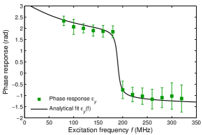
This high value for , and in particular the ratio , is in good agreement with the values obtained by measuring the steady state vortex core displacement Heyne et al. (2010), by observing thermally assisted domain wall dynamics Eltschka et al. (2010), or by imaging the frequency dependent vortex core trajectories Pollard et al. (2012). However, such a high non-adiabaticity at the vortex core is in contrast with the much lower non-adiabaticity measured for one dimensional domain walls Burrowes et al. (2009); Eltschka et al. (2010) and to the best of our knowledge, none of the existing models properly account for such a large enhancement. Spin relaxation produces a local non-adiabatic torque Zhang and Li (2004); Eltschka et al. (2010) that dominates in smoothly varying magnetic textures Tserkovnyak et al. (2006) but cannot explain the observed non-adiabaticity in vortices. Spin mistracking Tatara and Kohno (2004) is only significant for extremely sharp domain walls and exponentially vanishes for textures smoother than the spin precession length Tatara et al. (2007); Xiao et al. (2006); Lee et al. (2013). For instance, Ref. Lee et al., 2013 estimates for a domain wall width of . Such spin mistracking-induced non-adiabaticity can be dramatically enhanced in presence of spin-independent disorder Akosa et al. (2015), but it is questionable whether this effect remains efficient in textures much sharper than the mean free path. Finally, anomalous Hall effect produces non-adiabaticity in vortex cores only Manchon and Lee (2011) but in our system this contribution is negligible () due to the small Hall angle of permalloy () Nagaosa et al. (2010). Therefore, it appears that none of the models proposed to date reasonably explain the experimental observations Eltschka et al. (2010); Heyne et al. (2010); Pollard et al. (2012).
We look for a non-adiabatic torque that is present in vortices only, absent in transverse walls and that does not require extreme magnetization gradients nor strong disorder. Let us consider a clean magnetic system, free from disorder and spin relaxation, with a texture smooth enough so that spin mistracking (i.e. linear momentum transfer) can be neglected. In such a system, the itinerant electron spin experiences an emerging electromagnetic field in the frame of the local quantization axis Barnes and Maekawa (2007). This field can be expressed in terms of the magnetization spatio-temporal gradient as Tserkovnyak and Mecklenburg (2008); Zhang and Zhang (2009)
| (5) | |||
| (6) |
where refers to the spin projection on the local quantization axis , is Levi-Civita’s symbol and . This local electromagnetic field acts oppositely on the two opposite spins and emerges in the presence of magnetization gradient. As a result, the spin-dependent charge current reads
| (7) |
where is the conductivity of spin , is the electron density and is the applied electric field. The first term is the conventional Ohm’s law, the second term is induced by the so-called spin-motive force Barnes and Maekawa (2007), while the last term is the Hall effect generated by the local magnetic field. This emerging Hall effect is responsible for the topological Hall effect observed in topologically non-trivial magnetic textures such as skyrmions Neubauer et al. (2009). The induced spin current tensor can be then written
| (8) | |||||
where we defined , and is the conductivity. The absorption of this spin current produces a torque on the texture, such that , which reads
| (9) | |||||
The first term is the conventional adiabatic torque. The second term, proportional to the temporal gradient of the magnetization () is a correction to the magnetic damping Zhang and Zhang (2009) and the third term is the contribution from the emerging Hall effect.
To evaluate the effect of these torques on the magnetic vortex dynamics, we consider an isolated vortex core defined by , with for , for , and , where () is the inner (outer) radius of the vortex core. Assuming rigid vortex core motion Thiele (1973), where , we obtain the velocity of the vortex core
| (10) | |||||
| (11) |
where , and are the renormalized damping and non-adiabatic coefficient. Here, is the constant non-adiabaticity parameter measured, e.g., in transverse walls. Using m-1, m-3, , and emu/cc, we get nm2 and nm2. As a consequence, we obtain 0.055 and 0.017. These estimations, derived in the framework of the - model, disregard the hybridization usually encountered in transition metals. Furthermore, they assume adiabatic spin transport, neglecting spin mistracking and thereby underestimating the non-adiabaticity. Nevertheless, it clearly indicates that the local spin current induced by the emergent Hall effect dramatically enhances the non-adiabaticity of the spin-texture, an effect absent in one-dimensional domain walls, where only the magnetic damping is enhanced. Indeed, this local Hall effect involves a two-dimensional derivative [ in Eq. (9)], which vanishes for gradients along one dimension only.
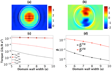
To obtain a more accurate estimate of the non-adiabaticity of the vortex core, we numerically compute the spin transport in a vortex core using the tight-binding model described in Ref. Akosa et al., 2015. The torque is obtained from the local nonequilibrium spin density , such that , being the exchange parameter. It is then parsed into adiabatic and non-adiabatic components, , reported on Fig. 3(a) and (b), respectively. While is distributed homogeneously around the center of the core, is asymmetric along the direction transverse to the applied electric field, reflecting the Hall effect origin of the torque. To evaluate the effective non-adiabaticity parameter, the torque components must be averaged over the volume of the core texture according to Thiele’s equation
| (12) | |||||
| (13) |
The results are shown in Fig. 3(c) as a function of the width of the core (red symbols). To compare, we also inserted the values obtained in the case of a transverse Néel domain wall of same width (black symbols). While the adiabatic torques are about the same order, the non-adiabaticity in the vortex core is much larger than in the transverse wall, which results in a large non-adiabaticity ratio [see Fig. 3(d)]. While only spin mistracking is present for the transverse wall, in vortex cores in addition the emergent Hall effect is present.
In conclusion, we have determined the non-adiabaticity locally of the vortex core using a highly sensitive phase shift method. In addition to the known minimum bound of the non-adiabaticity Pollard et al. (2012), we derived a maximum bound by analyzing the qualitative behaviour of the phase response, in summary we conclude . To explain such a high non-adiabaticity at the vortex core we proposed that the texture-induced emergent Hall effect generates non-local non-adiabatic torques. The values obtained by the theory are consistent with the experimental observations. These results are particularly encouraging for the manipulation of current-driven two and three dimensional textures such as skyrmions.
Acknowledgements.
The authors acknowledge support by the German Science Foundation (DFG SFB 767, KL1811, MAINZ GSC 266), the ERC (MASPIC 2007-Stg 208162), the EU (RTN Spinswitch, MRTN CT-2006-035327 , MAGWIRE FP7-ICT-2009-5 257707), COMATT and the Swiss National Science Foundation. Part of this work was carried out at the MAXYMUS scanning X-ray microscope at HZB, BESSY II in Berlin. The Advanced Light Source is supported by the Director, Office of Science, Office of Basic Energy Sciences, of the U.S. Department of Energy under Contract No. DE-AC02-05CH11231. A.M. and C.A. are supported by the King Abdullah University of Science and Technology (KAUST).References
- Boulle et al. (2011) O. Boulle, G. Malinowski, and M. Kläui, Mater. Sci. .Eng. R: Rep. 72, 159 (2011).
- Yamaguchi et al. (2004) A. Yamaguchi, T. Ono, S. Nasu, K. Miyake, K. Mibu, and T. Shinjo, Phys. Rev. Lett. 92, 077205 (2004).
- Yamada et al. (2007) K. Yamada, S. Kasai, Y. Nakatani, K. Kobayashi, H. Kohno, A. Thiaville, and T. Ono, Nat. Mater. 6, 270 (2007).
- Parkin et al. (2008) S. S. P. Parkin, M. Hayashi, and L. Thomas, Science 320, 190 (2008).
- Kent and Worledge (2015) A. D. Kent and D. C. Worledge, Nat. Nanotechnol. 10, 187 (2015).
- Jonietz et al. (2010) F. Jonietz, S. Mühlbauer, C. Pfleiderer, A. Neubauer, W. Münzer, A. Bauer, T. Adams, R. Georgii, P. Böni, R. a. Duine, K. Everschor, M. Garst, and A. Rosch, Science 330, 1648 (2010).
- Woo et al. (2015) S. Woo, K. Litzius, B. Krüger, M.-y. Im, L. Caretta, M. Mann, A. Krone, R. Reeve, M. Weigand, P. Agrawal, P. Fischer, M. Kläui, and G. S. D. Beach, , 1 (2015), arXiv:1502.07376v1 .
- Fert et al. (2013) A. Fert, V. Cros, and J. Sampaio, Nat. Nanotechnol. 8, 152 (2013).
- Zhang and Li (2004) S. Zhang and Z. Li, Phys. Rev. Lett. 93, 127204 (2004).
- Thiaville et al. (2005) A. Thiaville, Y. Nakatani, J. Miltat, and Y. Suzuki, Europhys. Lett. 69, 990 (2005).
- Tatara and Kohno (2004) G. Tatara and H. Kohno, Phys. Rev. Lett. 92, 086601 (2004).
- Kläui (2008) M. Kläui, J. Phys.: Condens. Matter 20, 313001 (2008).
- Heyne et al. (2010) L. Heyne, J. Rhensius, D. Ilgaz, A. Bisig, U. Rüdiger, M. Kläui, L. Joly, F. Nolting, L. J. Heyderman, J. U. Thiele, and F. Kronast, Phys. Rev. Lett. 105, 187203 (2010).
- Eltschka et al. (2010) M. Eltschka, M. Wötzel, J. Rhensius, S. Krzyk, U. Nowak, M. Kläui, T. Kasama, R. E. Dunin-Borkowski, L. J. Heyderman, H. J. van Driel, and R. A. Duine, Phys. Rev. Lett. 105, 056601 (2010).
- Pollard et al. (2012) S. D. Pollard, L. Huang, K. S. Buchanan, D. A. Arena, and Y. Zhu, Nat. Commun. 3, 1028 (2012).
- Burrowes et al. (2009) C. Burrowes, A. P. Mihai, D. Ravelosona, J.-V. Kim, C. Chappert, L. Vila, A. Marty, Y. Samson, F. Garcia-Sanchez, L. D. Buda-Prejbeanu, I. Tudosa, E. E. Fullerton, and J.-P. Attané, Nat. Phys. 6, 17 (2009).
- Bisig et al. (2010) A. Bisig, J. Rhensius, M. Kammerer, M. Curcic, H. Stoll, G. Schütz, B. Van Waeyenberge, K. W. Chou, T. Tyliszczak, L. J. Heyderman, S. Krzyk, A. von Bieren, and M. Kläui, Appl. Phys. Lett. 96, 152506 (2010).
- Bedau et al. (2007) D. Bedau, M. Kläui, S. Krzyk, U. Rüdiger, G. Faini, and L. Vila, Phys. Rev. Lett. 99, 146601 (2007).
- Kilcoyne et al. (2003) A. L. D. Kilcoyne, T. Tyliszczak, W. F. Steele, S. Fakra, P. Hitchcock, K. Franck, E. Anderson, B. Harteneck, E. G. Rightor, G. E. Mitchell, A. P. Hitchcock, L. Yang, T. Warwick, and H. Ade, J. Synchrotron Rad. 10, 125 (2003).
- Schütz et al. (1987) G. Schütz, W. Wagner, W. Wilhelm, P. Kienle, R. Zeller, R. Frahm, and G. Materlik, Phys. Rev. Lett. 58, 737 (1987).
- Kasai et al. (2006) S. Kasai, Y. Nakatani, K. Kobayashi, H. Kohno, and T. Ono, Phys. Rev. Lett. 97, 107204 (2006).
- Bolte et al. (2008) M. Bolte, G. Meier, B. Krüger, A. Drews, R. Eiselt, L. Bocklage, S. Bohlens, T. Tyliszczak, A. Vansteenkiste, B. Van Waeyenberge, K. W. Chou, A. Puzic, and H. Stoll, Phys. Rev. Lett. 100, 176601 (2008).
- Thiele (1973) A. A. Thiele, Phys. Rev. Lett. 30, 230 (1973).
- Huber (1982) D. L. Huber, Phys. Rev. B 26, 3758 (1982).
- Shibata et al. (2006) J. Shibata, Y. Nakatani, G. Tatara, H. Kohno, and Y. Otani, Phys. Rev. B 73, 020403 (2006).
- Guslienko et al. (2006) K. Y. Guslienko, X. F. Han, D. J. Keavney, R. Divan, and S. D. Bader, Phys. Rev. Lett. 96, 067205 (2006).
- Moriya et al. (2008) R. Moriya, L. Thomas, M. Hayashi, Y. B. Bazaliy, C. Rettner, and S. S. P. Parkin, Nat. Phys. 4, 368 (2008).
- Buchanan et al. (2006) K. S. Buchanan, P. E. Roy, F. Y. Fradin, K. Y. Guslienko, M. Grimsditch, S. D. Bader, and V. Novosad, J. Appl. Phys. 99, 08C707 (2006).
- Heyne and Kläui (2011) L. Heyne and M. Kläui, J. Appl. Phys. 109, 07C908 (2011).
- Krüger et al. (2010) B. Krüger, M. Najafi, S. Bohlens, R. Frömter, D. P. F. Möller, and D. Pfannkuche, Phys. Rev. Lett. 104, 077201 (2010).
- Tserkovnyak et al. (2006) Y. Tserkovnyak, H. J. Skadsem, A. Brataas, and G. E. W. Bauer, Phys. Rev. B 74, 144405 (2006).
- Tatara et al. (2007) G. Tatara, H. Kohno, J. Shibata, Y. Lemaho, and K.-J. Lee, J. Phys. Soc. Jpn. 76, 054707 (2007).
- Xiao et al. (2006) J. Xiao, A. Zangwill, and M. D. Stiles, Phys. Rev. B 73, 054428 (2006).
- Lee et al. (2013) K.-J. Lee, M. Stiles, H.-W. Lee, J.-H. Moon, K.-W. Kim, and S.-W. Lee, Phys. Rep. 531, 89 (2013).
- Akosa et al. (2015) C. A. Akosa, W.-S. Kim, A. Bisig, M. Kläui, K.-J. Lee, and A. Manchon, Phys. Rev. B 91, 094411 (2015).
- Manchon and Lee (2011) A. Manchon and K.-J. Lee, Appl. Phys. Lett. 99, 022504 (2011).
- Nagaosa et al. (2010) N. Nagaosa, J. Sinova, S. Onoda, A. H. MacDonald, and N. P. Ong, Rev. Mod. Phys. 82, 1539 (2010).
- Barnes and Maekawa (2007) S. E. Barnes and S. Maekawa, Phys. Rev. Lett. 98, 246601 (2007).
- Tserkovnyak and Mecklenburg (2008) Y. Tserkovnyak and M. Mecklenburg, Phys. Rev. B 77, 134407 (2008).
- Zhang and Zhang (2009) S. Zhang and S. S.-L. Zhang, Phys. Rev. Lett. 102, 086601 (2009).
- Neubauer et al. (2009) A. Neubauer, C. Pfleiderer, B. Binz, A. Rosch, R. Ritz, P. G. Niklowitz, and P. Böni, Phys. Rev. Lett. 102, 186602 (2009).