Nonreciprocal conversion between microwave and optical photons in electro-optomechanical systems
Abstract
We propose to demonstrate nonreciprocal conversion between microwave and optical photons in an electro-optomechanical system where a microwave mode and an optical mode are coupled indirectly via two non-degenerate mechanical modes. The nonreciprocal conversion is obtained in the broken time-reversal symmetry regime, where the conversion of photons from one frequency to the other is enhanced for constructive quantum interference while the conversion in the reversal direction is suppressed due to destructive quantum interference. It is interesting that the nonreciprocal response between the microwave and optical modes in the electro-optomechanical system appears at two different frequencies with opposite directions. The proposal can be used to realize nonreciprocal conversion between photons of any two distinctive modes with different frequencies. Moreover, the electro-optomechanical system can also be used to construct a three-port circulator for three optical modes with distinctively different frequencies by adding an auxiliary optical mode coupled to one of the mechanical modes.
pacs:
42.50.Wk, 42.50.Ex, 07.10.Cm, 11.30.ErI Introduction
Photons with wide range of frequencies play an important role in the quantum information processing and quantum networks YouJQPT05 ; DevoretSci13 ; KimbleNat08 ; RitterNat12 . Microwave photons can be fast manipulated for information processing YouJQPT05 ; DevoretSci13 , while the optical photons are more suitable for information transfer over long distance KimbleNat08 ; RitterNat12 . However, the microwave and optical systems are not compatible with each other naturally. In order to harness the advantages of photons with different frequencies, quantum interfaces are needed to convert photons of microwave and optical modes. A hybrid quantum system should be built by combining two or more physical systems XiangZLRMP13 ; JZhouSR14 .
Optomechanical (electromechnical) system is a very good candidate to serve as a quantum interface since the mechanical resonators can be easily coupled to various electromagnetic fields with distinctively different wavelengths through radiation pressure (for reviews, see Refs. KippenbergSci08 ; MarquardtPhy09 ; AspelmeyerPT12 ; AspelmeyerARX13 ). In recent years, enormous progresses have been made in the optomechanical (electromechnical) systems, such as normal-mode splitting in the strong coupling regime GroblacherNat09 ; TeufelNat11a , ground-state cooling of mechanical resonators TeufelNat11 ; ChanNat11 ; VerhagenNat12 , and coherent state transfer between itinerant microwave (optical) fields and a mechanical oscillator FiorePRL11 ; PalomakiNat13 . A hybrid electro-optomechanical system wherein a mechanical resonator is coupled to both microwave and optical modes simultaneously, provides us a quantum interface between microwave and optical systems RegalJPCS11 ; TianAPB15 . It was proposed theoretically that high fidelity quantum state transfer between microwave and optical modes can be realized by using the mechanically dark mode, which is immune to mechanical dissipation WangPRL12 ; TianPRL12 ; HKLiPRA13 ; ZhangKYPRL15 , and this proposal was demonstrated experimentally very soon HillNC12 ; DongSci12 ; LiuYPRL13 . The conversion between microwave and optical fields via electro-optomechanical systems has been achieved in several different experimental setups BochmannNPy13 ; BagciNat14 ; AndrewsNPy14 and it was shown that the wavelength conversion process is coherent and bidirectional AndrewsNPy14 . The electro-optomechanical systems have also been studied for strong entanglement generation between microwave photon and optical photon BarzanjehPRL12 ; WangYDPRL13 ; LTianPRL13 ; BarzanjehPRL15 , and such a strong continuous-variable (CV) entanglement can be exploited for the implementation of reversible CV quantum teleportation with a fidelity exceeding the no-cloning limit BarzanjehPRL12 and microwave quantum illumination BarzanjehPRL15 .
Nonreciprocal effect is the fundamental of isolators and circulators which are very important devices for information processing. Such effect appears usually due to the broken time-reversal symmetry PottonRPP04 ; ShadrivovNJP11 . There are two main avenues to break the time-reversal symmetry for photons: (i) using magneto-optical effects (e.g., Faraday rotation) FujitaAPL00 ; EspinolaOL04 ; ZamanAPL07 ; HaldanePRL08 ; ShojiAPL08 ; ZWangNat09 ; HadadPRL10 ; KhanikaevPRL10 ; LBiNPo11 ; ShojiOE12 and (ii) non-magnetic strategies by employing optical nonlinearity GalloAPL01 ; MingaleevJOSAB02 ; SoljacicOL03 ; RostamiOLT07 ; AlberucciOL08 ; LFanSci12 ; LFanOL13 ; AnandNL13 ; BiancalanaJAP08 ; MiroshnichenkoAPL10 ; CWangOE11 ; CWangSR12 ; KXiaOE13 ; LenferinkOE14 ; YYuarX14 or dynamic modulation YuNP09 ; KFangNPo12 ; ELiNC14 ; DoerrOL11 ; DoerrOE14 ; LiraPRL12 ; KFangPRL12 ; TzuangNPt14 ; MunozPRL14 ; YYangOE14 ; WangOE10 ; MSKangNP11 ; EuterNP10 ; RamezaniPRA10 ; LFengSci11 ; BPengNP14 ; WangPRL13 ; JHWuPRL14 ; HorsleyPRL13 . Non-magnetic optical nonreciprocity based on dynamic modulation has drawn more and more attentions in recent years and many structures have been demonstrated experimentally YuNP09 ; KFangNPo12 ; ELiNC14 ; DoerrOL11 ; DoerrOE14 ; LiraPRL12 ; TzuangNPt14 ; MunozPRL14 ; YYangOE14 ; MSKangNP11 ; EuterNP10 ; LFengSci11 ; BPengNP14 ; WangPRL13 or proposed theoretically JHWuPRL14 ; KFangPRL12 ; WangOE10 ; RamezaniPRA10 ; HorsleyPRL13 .
Nonreciprocal effect has also been developed in the context of optomechanical systems. Optical nonreciprocal effect was proposed in an optomechanical system consisting of an in-line Fabry-Perot cavity with one movable mirror and one fixed mirror based on the momentum difference between forward and backward-moving light beams ManipatruniPRL09 . Nonreciprocity was also studied in a microring optomechanical system when the optomechanical coupling is enhanced in one direction and suppressed in the other one by optically pumping the ring resonator HafeziOE12 or by resonant Brillouin scattering KimNPy15 ; CHDongNC15 . Some of us (Xu and Li) demonstrated the possibility of optical nonreciprocal response in a three-mode optomechanical system XuXWPRA15 where one mechanical mode is optomechanically coupled to two linearly-interacted optical modes simultaneously and the time-reversal symmetry of the system can be broken by tuning the phase difference between the two optomechanical coupling rates KochPRA10 ; HabrakenNJP12 ; SliwaPRX15 ; SchmidtOpt15 . As discussed in the theoretical outlook of a recent experiment FangKArx15 , optical nonreciprocity can be achieved in the distantly-coupled optomechanical systems with a waveguide that can mediate a tight-binding-type coupling for both the mechanical and optical cavity modes. It is worth mentioning that the two cavity modes given in Refs. XuXWPRA15 ; FangKArx15 are coupled to each other directly, so that the optical modes need to be resonant or nearly resonant. On how to obtain the nonreciprocal response between two cavity modes of distinctively different wavelengths (such as a microwave mode and an optical mode), there is still a lack of studies.
More recently, Metelmann and Clerk gave a general method for generating nonreciprocal behavior in cavity-based photonic devices by employing reservoir engineering MetelmannPRX15 . In the spirit of the general approach of Ref. MetelmannPRX15 , here we propose an optomechanical nonreciprocal device which allows photon routing with uni-directional links combining mechanically-mediated coherent and dissipative couplings. In our proposal, the links convert the signal carrier frequency from the microwave to the optical domain (or vice versa). The transmission of photons from one mode to the other is determined by the quantum interference between the two paths through the mechanically-mediated coherent and dissipative couplings. Due to the broken time-reversal symmetry, the nonreciprocity is obtained when the transmission of photons from one mode to the other is enhanced for constructive quantum interference while the transmission in the reversal direction is suppressed with destructive quantum interference. It is interesting that the electro-optomechanical system shows nonreciprocal response between the optical and microwave modes at two different frequencies with opposite directions. Moreover, after adding an auxiliary optical mode to couple to one of the mechanical modes, the electro-optomechanical system can be used as a three-port circulator for three optical modes with distinctively different frequencies.
This paper is organized as follows: In Sec. II, the Hamiltonian of an electro-optomechanical system is introduced and the spectra of the optical output fields are given. The Nonreciprocal conversion between the microwave and optical photons is shown in Sec. III and a three-port circulator for three optical modes with distinctively different frequencies is discussed in Sec. IV. Finally, we summarize the results in Sec. V.
II Model
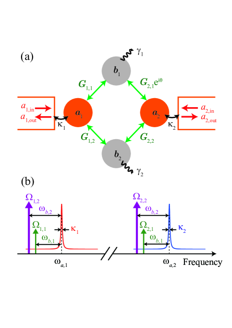
As schematically shown in Fig. 1(a), the electro-optomechanical system is composed of two cavity modes (a microwave mode and an optical mode), each of which is coupled to two non-degenerate mechanical modes. The two cavity modes cannot couple to each other directly because of the vast difference of their wavelengths. The Hamiltonian of the electro-optomechanical system is ()
| (1) | |||||
where () is the bosonic annihilation (creation) operator of the cavity mode with resonance frequency , () is the bosonic annihilation (creation) operator of the mechanical mode with resonance frequency , and is the electromechanical (optomechanical) coupling strength between the cavity mode and the mechanical mode (). The cavity mode is driven by a two-tone laser at two frequencies and with amplitudes and in the well resolved sidebands () as schematically shown in Fig. 1(b), where is the decay rate of the cavity mode and is the damping rate of the mechanical mode . is the phase of the driving field. We can write each operators for the cavity modes as the sum of its quantum fluctuation operator and classical mean value, . In the condition that min, the classical part can be given approximately as , where the classical amplitude is determined by solving the classical equation of motion with only cavity drive at frequency WangYDPRL13 ; LTianPRL13 ; KronwaldPRA13 ; OjanenPRA14 . To linearize the Hamiltonian (1), we take so that we can only keep the first-order terms in the small quantum fluctuation operators, then the linearized Hamiltonian in the interaction picture with respect to is obtained as
| (2) | |||||
where is the effective electromechanical (optomechanical) coupling strength and the non-resonant and counter-rotating terms have been neglected. The phase of can be controlled by tuning the phases of the driving fields. Actually, here the phases of (three of them) have been absorbed by redefining the operators and , and only the total phase difference between them has physical effects. Without loss of generality, is only kept in the terms of and in Eq. (2) and the following derivation.
By the Heisenberg equation and taking into account the damping and corresponding noise terms, we get the quantum Langevin equations (QLEs) for the operators of the optical and mechanical modes:
| (3) |
with the vector of fluctuation operators, the vector of input operators, the diagonal damping matrix , and the coefficient matrix
| (4) |
and are the input quantum fields with zero mean values. The system is stable only if the real parts of all the eigenvalues of matrix are positive. The stability conditions can be given explicitly by using the Routh-Hurwitz criterion DeJesusPRA87 ; Gradshteyn80 ; PaternostroNJP06 ; VitaliPRL07 ; GhobadiPRA11 . However, they are too cumbersome to be given here. All of the parameters used in the following satisfy the stability conditions.
Let us introduce the Fourier transform for an operator
| (5) |
| (6) |
then the solution to the QLEs (3) in the frequency domain can be given by
| (7) |
where denotes the identity matrix. Using the standard input-output theory GardinerPRA85 , the Fourier transform of the output vector is obtained as AgarwalPRA12
| (8) |
where
| (9) |
The spectrum of the field with operator is defined as
| (10) |
then the spectra of the input quantum fields, , are obtained as and , where the term “1” results from the effect of vacuum noise and () is the Fourier transform of () (for ). The relation between the vector of the spectrum of the output fields and the vector of the spectrum of the input fields is given by
| (11) |
where , . Here is the transmission matrix with the element (for ) denoting the scattering probability from mode to mode . In the next section, we will focus on the photon scattering probability between the two cavity modes. For simplicity, we define and , where represents the element at the -th row and -th column of the matrix given in Eq. (9).
III Optical nonreciprocity
We assume that the effective optomechanical coupling strengths , the decay rates of the cavity modes and the damping rate of the two mechanical modes satisfy the relation
| (12) |
i.e., the damping of the mechanical mode is much slower than the decay of the cavity modes and this is usually satisfied; the damping of the mechanical mode is much faster than the decay of the cavity modes and this condition can be realized by coupling the mechanical mode to an auxiliary cavity mode (more details are shown in next section). Under the assumption (12), the operators of the mechanical mode can be eliminated from QLE (3) adiabatically JahnePRA09 ; XWXuPRA15 , then we have
| (13) |
with the vector of fluctuation operators, the vector of input operators, the diagonal damping matrices , and the coefficient matrix
| (14) |
where the dissipative coupling strength , and the decay rates and are induced by the mechanical mode . Using the Fourier transform and the standard input-output relation, we can get the output vector in the frequency domain as
| (15) |
where
| (16) |
| (17) |
The explicit expressions of the transmission coefficients between the two cavity modes are of the form
| (18) |
| (19) |
where
| (20) | |||||
Here is the total damping rate of the cavity mode given by
| (21) |
The -dependent effective coupling strength () (coherent coupling), the effective damping rate , and the frequency shift induced by the mechanical mode , are given by
| (22) |
| (23) |
| (24) |
| (25) |
We would like to note that the coherent coupling strength () and damping rates induced by the mechanical mode are dependent on the frequency of the input photons, while the dissipative coupling strength and decay rates induced by the mechanical mode are independent on the frequency . Moreover, there are frequency shifts induced by the mechanical mode but there are almost no frequency shifts induced by the mechanical mode .
Equations (18) and (19) imply that the transmission coefficients between the two cavity modes are determined by the quantum interference of the two paths through the mechanically-mediated coherent and dissipative couplings [i.e., () and ]. In constructive interference, the transmission rates will be enhanced; in contrast, the transmission rate will be suppressed with destructive interference. The nonreciprocity is obtained in the condition that one of the transmission coefficients [ or ] is enhanced and the other one is suppressed. The nonreciprocity can be intuitively understood from the schematic diagram shown in Fig. 1(a). The input photons from one cavity mode to the other one undergo a Mach-Zehnder-type interference: one path is the hopping through the mechanical mode and the other path is the hopping through the mechanical mode . The phase of the first path is determined by the driven fields as shown in Eq. (2). The nonreciprocal response of the electro-optomechanical system is induced by this phase, which is gauge invariant and is associated with the broken time-reversal symmetry for the system KochPRA10 ; HabrakenNJP12 ; SliwaPRX15 .
The perfect nonreciprocity is obtained as or . In order to satisfy or , from Eqs. (18) and (19), we should have
| (26) |
Under the assumption (12), i.e., , we have
| (27) |
and
| (28) |
After substituting Eq. (26) into Eqs. (18) and (19), we obtain the condition for or as
| (29) |
For simplicity we choose
| (30) |
then the condition in Eq. (29) reduces to
| (31) |
Thus with the assumption (12), the nonreciprocity is obtained as the effective electromechanical (optomechanical) coupling strengths satisfy the conditions (for simplicity, we choose and )
| (32) | |||||
| (33) |
and the perfect nonreciprocity appears around the frequencies
| (34) |
As a specific example, under the conditions given in Eqs. (12), (32) and (33), by choosing , the transmission coefficients at frequency are given by
| (35) |
and the transmission coefficients at frequency are given by
| (36) |
Under the same conditions given in Eqs. (12), (32) and (33), if we choose , when , the transmission coefficients are given by
| (37) |
and when , the transmission coefficients are given by
| (38) |
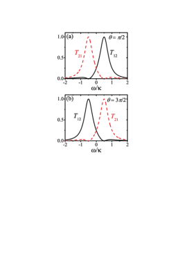
In Fig. 2, the scattering probabilities between the two cavity modes and are plotted as functions of the frequency of the incoming signal for different phase difference, where the parameters are given as , , , , and . When ( is an integer), the time-reversal symmetry is broken and the electro-optomechanical system exhibits a non-reciprocal response. The optimal optical nonreciprocal response is obtained when or . As shown in Fig. 2, the electro-optomechanical system shows nonreciprocal response between the optical and microwave modes at two different frequencies with opposite directions: when as shown in Fig. 2 (a), we have , at and , at ; when as shown in Fig. 2 (b), we have , at and , at .
IV Optical circulator
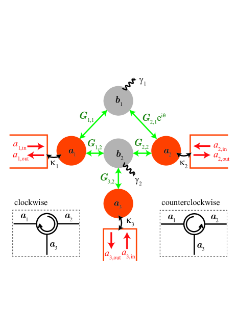
In the derivation of Sec. III, we have assumed that , where should be the total damping rate of the mechanical mode . This assumption seems counterintuitive since usually the damping rate of the mechanical mode is smaller than the decay rate of the cavity mode. In this section, we will show that even when the intrinsic damping rate of the mechanical mode (denoted by ) is much smaller than the cavity decay rate , the total damping rate of the mechanical mode can also satisfy the condition (12) when the mechanical resonator is coupled to an auxiliary cavity mode (cavity mode ), as shown in Fig. 3. Moreover, we will present the spectra of the output optical fields from the hybrid system which involves the electro-optomechanical system and the auxiliary cavity mode. We will show that the hybrid system can be used as a three-port circulator for three optical modes with distinctively different wavelengths at two different frequencies with opposite directions.
The Hamiltonian of the hybrid system for the electro-optomechanical system with the auxiliary cavity mode is given by
| (39) |
and
| (40) | |||||
where () is the bosonic annihilation (creation) operator of the auxiliary cavity mode with resonance frequency and is the electromechanical (optomechanical) coupling strength between the cavity mode and the mechanical mode . The cavity mode is driven with strength at frequency . In the interaction picture with respect to , the linearized Hamiltonian of Eq. (39) can be written as
| (41) |
with the effective optomechanical coupling strength . Without loss of generality, is assumed to be real. The classical amplitude is determined by solving the classical equation of motion with only the cavity drive at frequency .
The QLEs for the operators of the hybrid system is given as
| (42) |
with the vector of fluctuation operators, the vector of input operators, the diagonal damping matrix , and the coefficient matrix
| (43) |
Using the Fourier transform and the standard input-output relation, we can express the output vector as
| (44) |
where
| (45) |
Under the assumption that the decay rate of the cavity mode is much larger than the intrinsic damping rate of the mechanical mode and the effective optomechanical coupling strength between the mechanical mode and the cavity mode , i.e., , we can adiabatically eliminate the cavity mode , then we obtained the QLEs (3) with the replacement
| (46) |
in the coefficient matrix, and the replacement
| (47) |
in the input operators vector . Here is the effective damping rate of the mechanical mode induced by the auxiliary cavity mode ,
| (48) |
can be controlled by tuning the strength of the driving field on the cavity mode . Even if the intrinsic damping rate of the mechanical mode is much smaller than the decay rates of the cavity modes, i.e., , the total damping rate of the mechanical mode (i.e., ) still can satisfy the condition (12) when .
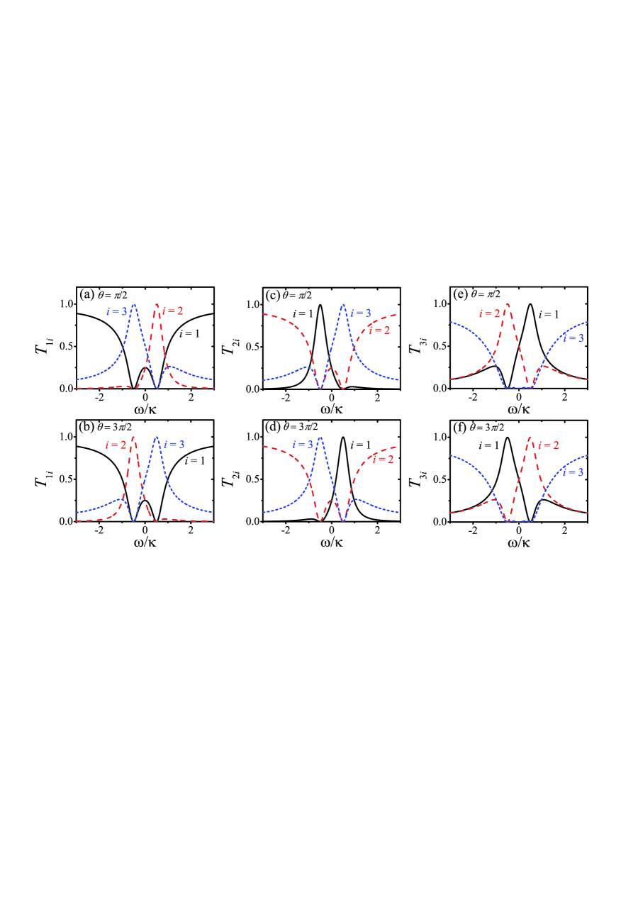
In the following, we will study the scattering probability between the three cavity modes. For convenience of discussion, we set (). Using Eq. (45), we now show the numerical results of the scattering probabilities between the three cavity modes. As shown in Fig. 4, the electro-optomechanical system shows optical circulator behavior for the three cavity modes at two different frequencies () with opposite directions. When as shown in Figs. 4 (a), (c) and (e), at frequency , and the other scattering probabilities equal to zero; at frequency , and the other scattering probabilities equal to zero. When , as shown in Figs. 4 (b), (d) and (f), at frequency , and the other scattering probabilities equal to zero; at frequency , and the other scattering probabilities equal to zero. That is when , the signal is transferred from one cavity mode to another either clockwisely () at frequency or counterclockwisely () at frequency . In contrast to , when , the signal is transferred either counterclockwisely at frequency or clockwisely at frequency .
V Conclusions
In summary, we have demonstrated the nonreciprocal conversion between microwave and optical photons in electro-optomechanical systems. The electro-optomechanical system shows nonreciprocal response between the microwave and optical modes at two different frequencies with opposite directions. The proposal is general and can be used to realize nonreciprocal conversion between photons of two arbitrarily different frequencies. Moreover, the electro-optomechanical system with an auxiliary optical mode can be used as a three-port circulator for three optical modes with arbitrarily different frequencies at two different frequencies with opposite directions. The electro-optomechanical system with broken time-reversal symmetry will open up a different kind of quantum interface in the quantum information processing and quantum networks.
Acknowledgement
X.-W.X. thanks Professor Nian-Hua Liu for fruitful discussions. Y.L. is supported by the National Basic Research Program of China (973 Program) under Grants No. 2014CB921403. A.-X.C. is supported by the National Natural Science Foundation of China (NSFC) under Grants No. 11365009. Y.-x.L. is supported by NSFC under Grant Nos. 61328502 and 61025022, the Tsinghua University Initiative Scientific Research Program, and the Tsinghua National Laboratory for Information Science and Technology (TNList) Cross-discipline Foundation. X.-W.X. is supported by the Startup Foundation for Doctors of East China Jiaotong University, under Grant No. 26541059.
References
- (1) J. Q. You and F. Nori, Superconducting circuits and quantum information, Phys. Today 58(11), 42 (2005).
- (2) M. H. Devoret and R. J. Schoelkopf, Superconducting Circuits for Quantum Information: An Outlook, Science 339, 1169 (2013).
- (3) H. J. Kimble, The quantum internet, Nature (London) 453, 1023 (2008).
- (4) S. Ritter, C. Nolleke, C. Hahn, A. Reiserer, A. Neuzner, M. Uphoff, M. Mucke, E. Figueroa, J. Bochmann, and G. Rempe, An elementary quantum network of single atoms in optical cavities, Nature (London) 484, 195 (2012).
- (5) Z. L. Xiang, S. Ashhab, J. Q. You, and F. Nori, Hybrid quantum circuits: Superconducting circuits interacting with other quantum systems, Rev. Mod. Phys. 85, 623 (2013).
- (6) J. Zhou, Y. Hu, Z. Q. Yin, Z. D. Wang, S. L. Zhu, and Z. Y. Xue, High fidelity quantum state transfer in electromechanical systems with intermediate coupling, Sci. Rep. 4, 6237 (2014).
- (7) T. J. Kippenberg and K. J. Vahala, Cavity Optomechanics: Back-Action at the Mesoscale, Science 321, 1172 (2008).
- (8) F. Marquardt and S. M. Girvin, Optomechanics, Physics 2, 40 (2009).
- (9) M. Aspelmeyer, P. Meystre, and K. Schwab, Quantum optomechanics, Phys. Today 65(7), 29 (2012).
- (10) M. Aspelmeyer, T. J. Kippenberg, and F. Marquardt, Cavity Optomechanics, Rev. Mod. Phys. 86, 1391 (2014).
- (11) S. Groblacher, K. Hammerer, M. R. Vanner, and M. Aspelmeyer, Observation of strong coupling between a micromechanical resonator and an optical cavity field, Nature (London) 460, 724 (2009).
- (12) J. D. Teufel, D. Li, M. S. Allman, K. Cicak, A. J. Sirois, J. D. Whittaker, and R. W. Simmonds, Circuit cavity electromechanics in the strong-coupling regime, Nature (London) 471, 204 (2011).
- (13) J. D. Teufel, T. Donner, D. Li, J. W. Harlow, M. S. Allman, K. Cicak, A. J. Sirois, J. D. Whittaker, K. W. Lehnert, and R. W. Simmonds, Sideband cooling of micromechanical motion to the quantum ground state, Nature (London) 475, 359 (2011).
- (14) J. Chan, T. P. M. Alegre, A. H. Safavi-Naeini, J. T. Hill, A. Krause, S. Groblacher, M. Aspelmeyer, and O. Painter, Laser cooling of a nanomechanical oscillator into its quantum ground state, Nature (London) 478, 89 (2011).
- (15) E. Verhagen, S. Deleglise, S. Weis, A. Schliesser, and T. J. Kippenberg, Quantum-coherent coupling of a mechanical oscillator to an optical cavity mode, Nature (London) 482, 63 (2012).
- (16) V. Fiore, Y. Yang, M. C. Kuzyk, R. Barbour, L. Tian, and H. Wang, Storing Optical Information as a Mechanical Excitation in a Silica Optomechanical Resonator, Phys. Rev. Lett. 107, 133601 (2011).
- (17) T. A. Palomaki, J. W. Harlow, J. D. Teufel, R. W. Simmonds, and K. W. Lehnert, Coherent state transfer between itinerant microwave fields and a mechanical oscillator, Nature (London) 495, 210 (2013).
- (18) C. A. Regal and K.W. Lehnert, From cavity electromechanics to cavity optomechanics, J. Phys. Conf. Ser. 264, 012025 (2011).
- (19) L. Tian, Optoelectromechanical transducer: Reversible conversion between microwave and optical photons, Ann. Phys. (Berlin) 527, 1 (2015).
- (20) Y. D. Wang and A. A. Clerk, Using Interference for High Fidelity Quantum State Transfer in Optomechanics, Phys. Rev. Lett. 108, 153603 (2012).
- (21) L. Tian, Adiabatic State Conversion and Pulse Transmission in Optomechanical Systems, Phys. Rev. Lett. 108, 153604 (2012).
- (22) H. K. Li, X. X. Ren, Y. C. Liu, and Y. F. Xiao, Photon-photon interactions in a largely detuned optomechanical cavity, Phys. Rev. A 88, 053850 (2013).
- (23) K. Y. Zhang, F. Bariani, Y. Dong, W. P. Zhang, and P. Meystre, Proposal for an Optomechanical Microwave Sensor at the Subphoton Level, Phys. Rev. Lett. 114, 113601 (2015).
- (24) J. T. Hill, A. H. Safavi-Naeini, J. Chan, O. Painter, Coherent optical wavelength conversion via cavity optomechanics, Nat. Comm. 3, 1196 (2012).
- (25) C. Dong, V. Fiore, M. C. Kuzyk, and H. Wang, Optomechanical Dark Mode, Science 338, 1609 (2012).
- (26) Y. Liu, M. Davanço, V. Aksyuk, and K. Srinivasan, Electromagnetically Induced Transparency and Wideband Wavelength Conversion in Silicon Nitride Microdisk Optomechanical Resonators, Phys. Rev. Lett. 110, 223603 (2013).
- (27) T. Bagci, A. Simonsen, S. Schmid, L. G. Villanueva, E. Zeuthen, J. Appel, J. M. Taylor, A. Sørensen, K.Usami, A. Schliesser, and E. S. Polzik, Optical detection of radio waves through a nanomechanical transducer, Nature (London) 507, 81 (2014).
- (28) R. W. Andrews, R. W. Peterson, T. P. Purdy, K. Cicak, R. W. Simmonds, C. A. Regal, and K. W. Lehnert, Bidirectional and efficient conversion between microwave and optical light, Nature Phys. 10, 321 (2014).
- (29) J. Bochmann, A. Vainsencher, D. D. Awschalom, and A. N. Cleland, Nanomechanical coupling between microwave and optical photons, Nature Phys. 9, 712 (2013);
- (30) Sh. Barzanjeh, M. Abdi, G. J. Milburn, P. Tombesi, and D. Vitali, Reversible Optical-to-Microwave Quantum Interface, Phys. Rev. Lett. 109, 130503 (2012)
- (31) Y. D. Wang and A. A. Clerk, Reservoir-Engineered Entanglement in Optomechanical Systems, Phys. Rev. Lett. 110, 253601 (2013).
- (32) L. Tian, Robust Photon Entanglement via Quantum Interference in Optomechanical Interfaces, Phys. Rev. Lett. 110, 233602 (2013).
- (33) Sh. Barzanjeh, S. Guha, C. Weedbrook, D. Vitali, J. H. Shapiro, and S. Pirandola, Microwave Quantum Illumination, Phys. Rev. Lett. 114, 080503 (2015).
- (34) R. J. Potton, Reciprocity in optics, Rep. Prog. Phys. 67, 717 (2004).
- (35) I. V. Shadrivov, V. A. Fedotov, D. A. Powell, Y. S. Kivshar, and N. I. Zheludev, Electromagnetic wave analogue of an electronic diode, New J. Phys. 13, 033025 (2011).
- (36) J. Fujita, M. Levy, R. M. Osgood, L.Wilkens, and H. Dötsch, Waveguide optical isolator based on Mach-Zehnder interferometer, Appl. Phys. Lett. 76, 2158 (2000).
- (37) R. L. Espinola, T. Izuhara, M. C. Tsai, R. M. Osgood Jr., H. Dötsch, Magneto-optical nonreciprocal phase shift in garnet/silicon-on-insulator waveguides, Opt. Lett. 29, 941 (2004).
- (38) T. R. Zaman, X. Guo, R. J. Ram, Faraday rotation in an InP waveguide, Appl. Phys. Lett. 90, 023514 (2007).
- (39) F. D. M. Haldane and S. Raghu, Possible Realization of Directional Optical Waveguides in Photonic Crystals with Broken Time-Reversal Symmetry, Phys. Rev. Lett. 100, 013904 (2008).
- (40) Y. Shoji, T. Mizumoto, H. Yokoi, I. Hsieh, and R. M. Osgood Jr., Magneto-optical isolator with silicon waveguides fabricated by direct bonding, Appl. Phys. Lett. 92, 071117 (2008).
- (41) Z. Wang, Y. Chong, J. D. Joannopoulos, and M. Soljačić, Observation of unidirectional backscattering-immune topological electromagnetic states, Nature (London) 461, 772 (2009).
- (42) Y. Hadad and B. Z. Steinberg, Magnetized Spiral Chains of Plasmonic Ellipsoids for One-Way Optical Waveguides, Phys. Rev. Lett. 105, 233904 (2010).
- (43) A. B. Khanikaev, S. H. Mousavi, G. Shvets, and Y. S. Kivshar, One-Way Extraordinary Optical Transmission and Nonreciprocal Spoof Plasmons, Phys. Rev. Lett. 105, 126804 (2010).
- (44) L. Bi, J. Hu, P. Jiang, D. H. Kim, G. F. Dionne, L. C. Kimerling, and C. A. Ross, On-chip optical isolation in monolithically integrated non-reciprocal optical resonators, Nat. Photon. 5, 758 (2011).
- (45) Y. Shoji, M. Ito, Y. Shirato, and T. Mizumoto, MZI optical isolator with Si-wire waveguides by surface-activated direct bonding, Opt. Express 20, 18440 (2012).
- (46) K. Gallo, G. Assanto, K. R. Parameswaran, and M. M. Fejer, All-optical diode in a periodically poled lithium niobate waveguide, Appl. Phys. Lett. 79, 314 (2001).
- (47) S. F. Mingaleev, Y. S. Kivshar, Nonlinear transmission and light localization in photonic-crystal waveguides, J. Opt. Soc. Am. B 19, 2241 (2002).
- (48) M. Soljačić, C. Luo, J. D. Joannopoulos, S. Fan, Nonlinear photonic crystal microdevices for optical integration, Opt. Lett. 28, 637 (2003).
- (49) A. Rostami, Piecewise linear integrated optical device as an optical isolator using two-port nonlinear ring resonators, Opt. Laser Technol. 39, 1059 (2007).
- (50) A. Alberucci and G. Assanto, All-optical isolation by directional coupling, Opt. Lett. 33, 1641 (2008).
- (51) L. Fan, J. Wang, L. T. Varghese, H. Shen, B. Niu, Y. Xuan, A. M. Weiner, and M. Qi, An All-Silicon Passive Optical Diode, Science 335, 447 (2012).
- (52) L. Fan, L. T. Varghese, J. Wang, Y. Xuan, A. M. Weiner, and M. Qi, Silicon optical diode with 40 dB nonreciprocal transmission, Opt. Lett. 38, 1259 (2013).
- (53) B. Anand, R. Podila, K. Lingam, S. R. Krishnan, S. S. S. Sai, R. Philip, and A. M. Rao, Optical Diode Action from Axially Asymmetric Nonlinearity in an All-Carbon Solid-State Device, Nano Lett. 13, 5771 (2013).
- (54) F. Biancalana, All-optical diode action with quasiperiodic photonic crystals, J. Appl. Phys. 104, 093113 (2008).
- (55) A. E. Miroshnichenko, E. Brasselet, and Y. S. Kivshar, Reversible optical nonreciprocity in periodic structures with liquid crystals, Appl. Phys. Lett. 96, 063302 (2010).
- (56) C. Wang, C. Zhou, and Z. Li, On-chip optical diode based on silicon photonic crystal heterojunctions, Opt. Express 19, 26948 (2011).
- (57) C. Wang, X. Zhong, and Z. Li, Linear and passive silicon optical isolator, Sci. Rep. 2, 674 (2012).
- (58) K. Xia, M. Alamri, and M. S. Zubairy, Ultrabroadband nonreciprocal transverse energy flow of light in linear passive photonic circuits, Opt. Express 21, 25619 (2013).
- (59) E. J. Lenferink, G. Wei, and N. P. Stern, Coherent optical non-reciprocity in axisymmetric resonators, Opt. Express 22, 16099 (2014).
- (60) Y. Yu, Y. Chen, H. Hu, W. Xue, K. Yvind, and J. Mork, Nonreciprocal transmission in a nonlinear photonic-crystal Fano structure with broken symmetry, Laser Photonics Rev. 9, 241 (2015).
- (61) Z. F. Yu and S. H. Fan, Complete optical isolation created by indirect interband photonic transitions, Nat. Photon. 3, 91 (2009).
- (62) K. Fang, Z. Yu, and S. Fan, Realizing effective magnetic field for photons by controlling the phase of dynamic modulation, Nat. Photon. 6, 782 (2012).
- (63) E. Li, B. J. Eggleton, K. Fang, and S. Fan, Photonic Aharonov-Bohm effect in photon-phonon interactions, Nat. Commun. 5, 3225 (2014).
- (64) C. R. Doerr, N. Dupuis, and L. Zhang, Optical isolator using two tandem phase modulators, Opt. Lett. 36, 4293 (2011).
- (65) C. R. Doerr, L. Chen, and D. Vermeulen, Silicon photonics broadband modulation-based isolator, Opt. Express 22, 4493 (2014).
- (66) H. Lira, Z. F. Yu, S. H. Fan, and M. Lipson, Electrically Driven Nonreciprocity Induced by Interband Photonic Transition on a Silicon Chip, Phys. Rev. Lett. 109, 033901 (2012).
- (67) L. D. Tzuang, K. Fang, P. Nussenzveig, S. Fan, and M. Lipson, Non-reciprocal phase shift induced by an effective magnetic flux for light, Nat. Photon. 8, 701 (2014).
- (68) M. Castellanos Munoz, A. Y. Petrov, L. O’Faolain, J. Li, T. F. Krauss, and M. Eich, Optically Induced Indirect Photonic Transitions in a Slow Light Photonic Crystal Waveguide, Phys. Rev. Lett. 112, 053904 (2014).
- (69) Y. Yang, C. Galland, Y. Liu, K. Tan, R. Ding, Q. Li, K. Bergman, T. Baehr-Jones, and M. Hochberg, Experimental demonstration of broadband Lorentz non-reciprocity in an integrable photonic architecture based on Mach-Zehnder modulators, Opt. Express 22, 17409 (2014).
- (70) M. S. Kang, A. Butsch, and P. S. J. Russell, Reconfigurable light-driven opto-acoustic isolators in photonic crystal fibre, Nat. Photonics 5, 549 (2011).
- (71) C. Eüter, K. G. Makris, R. EI-Ganainy, D. N. Christodoulides, M. Segev, and D. Kip, Observation of parity-time symmetry in optics, Nat. Phys. 6, 192 (2010).
- (72) L. Feng, M. Ayache, J. Q. Huang, Y. L. Xu, M. H. Lu, Y. F. Chen, Y. Fainman, and A. Scherer, Nonreciprocal Light Propagation in a Silicon Photonic Circuit, Science 333, 729 (2011).
- (73) B. Peng, S. K. Özdemir, F. Lei, F. Monifi, M. Gianfreda, G. L. Long, S. H. Fan, F. Nori, C. M. Bender, and L. Yang, Parity-time-symmetric whispering-gallery microcavities, Nat. Phys. 10, 394 (2014).
- (74) D. W. Wang, H. T. Zhou, M. J. Guo, J. X. Zhang, J. Evers, and S. Y. Zhu, Optical Diode Made from a Moving Photonic Crystal, Phys. Rev. Lett. 110, 093901 (2013).
- (75) Q. Wang, F. Xu, Z. Y. Yu, X. S. Qian, X. K. Hu, Y. Q. Lu, and H. T. Wang, A bidirectional tunable optical diode based on periodically poled LiNbO3, Opt. Express 18, 7340 (2010).
- (76) H. Ramezani, T. Kottos, R. El-Ganainy, and D. N. Christodoulides, Unidirectional nonlinear -symmetric optical structures, Phys. Rev. A 82, 043803 (2010).
- (77) K. Fang, Z. Yu, and S. Fan, Photonic Aharonov-Bohm Effect Based on Dynamic Modulation, Phys. Rev. Lett. 108, 153901 (2012).
- (78) S. A. R. Horsley, J. H. Wu, M. Artoni, and G. C. La Rocca, Optical Nonreciprocity of Cold Atom Bragg Mirrors in Motion, Phys. Rev. Lett. 110, 223602 (2013).
- (79) J. H. Wu, M. Artoni, and G. C. La Rocca, Non-Hermitian Degeneracies and Unidirectional Reflectionless Atomic Lattices, Phys. Rev. Lett. 113, 123004 (2014).
- (80) S. Manipatruni, J. T. Robinson, and M. Lipson, Optical Nonreciprocity in Optomechanical Structures, Phys. Rev. Lett. 102, 213903 (2009).
- (81) M. Hafezi and P. Rabl, Optomechanically induced non-reciprocity in microring resonators, Opt. Express 20, 7672 (2012).
- (82) J. Kim, M. C. Kuzyk, K. Han, H. Wang, and G. Bahl, Non-reciprocal Brillouin scattering induced transparency, Nat. Phys. 11, 275 (2015).
- (83) C. H. Dong, Z. Shen, C. L. Zou, Y. L. Zhang, W. Fu, and G. C. Guo, Brillouin-scattering-induced transparency and non-reciprocal light storage, Nature Commun. 6, 6193 (2015).
- (84) X. W. Xu and Y. Li, Optical nonreciprocity and optomechanical circulator in three-mode optomechanical systems, Phys. Rev. A 91, 053854 (2015).
- (85) J. Koch, A. A. Houck, K. L. Hur, and S. M. Girvin, Time-reversal-symmetry breaking in circuit-QED-based photon lattices, Phys. Rev. A 82, 043811 (2010).
- (86) S. J. M. Habraken, K. Stannigel, M. D. Lukin, P. Zoller, and P Rabl, Continuous mode cooling and phonon routers for phononic quantum networks, New J. Phys. 14, 115004 (2012).
- (87) K. M. Sliwa, M. Hatridge, A. Narla, S. Shankar, L. Frunzio, R. J. Schoelkopf, and M. H. Devoret, Reconfigurable Josephson Circulator/Directional Amplifier, Phys. Rev. X 5, 041020 (2015).
- (88) M. Schmidt, S. Kessler, V. Peano, O. Painter, and F. Marquardt, Optomechanical creation of magnetic fields for photons on a lattice, Optica 2, 635 (2015).
- (89) K. Fang, M. H. Matheny, X. Luan, and O. Painter, Phonon routing in integrated optomechanical cavity-waveguide systems, arXiv:1508.05138v1 [physics.optics].
- (90) A. Metelmann and A. A. Clerk, Nonreciprocal Photon Transmission and Amplification via Reservoir Engineering, Phys. Rev. X 5, 021025 (2015).
- (91) A. Kronwald, F. Marquardt and A. A. Clerk, Arbitrarily large steady-state bosonic squeezing via dissipation, Phys. Rev. A 88, 063833 (2013).
- (92) T. Ojanen and K. Børkje, Ground-state cooling of mechanical motion in the unresolved sideband regime by use of optomechanically induced transparency, Phys. Rev. A 90, 013824 (2014).
- (93) E. X. DeJesus and C. Kaufman, Routh-Hurwitz criterion in the examination of eigenvalues of a system of nonlinear ordinary differential equations, Phys. Rev. A 35, 5288 (1987).
- (94) I. S. Gradshteyn and I. M. Ryzhik, in Table of Integrals, Series and Products (Academic, Orlando, 1980), p. 1119.
- (95) M. Paternostro, S. Gigan, M. S. Kim, F. Blaser, H. R. Böhm, and M. Aspelmeyer, Reconstructing the dynamics of a movable mirror in a detuned optical cavity, New J. Phys. 8, 107 (2006).
- (96) D. Vitali, S. Gigan, A. Ferreira, H. R. Böhm, P. Tombesi, A. Guerreiro, V. Vedral, A. Zeilinger, and M. Aspelmeyer, Optomechanical Entanglement between a Movable Mirror and a Cavity Field, Phys. Rev. Lett. 98, 030405 (2007).
- (97) R. Ghobadi, A. R. Bahrampour, and C. Simon, Quantum optomechanics in the bistable regime, Phys. Rev. A 84, 033846 (2011).
- (98) C. W. Gardiner and M. J. Collett, Input and output in damped quantum systems: Quantum stochastic differential equations and the master equation, Phys. Rev. A 31, 3761 (1985).
- (99) G. S. Agarwal and S. Huang, Optomechanical systems as single-photon routers, Phys. Rev. A 85, 021801(R) (2012).
- (100) K. Jähne, C. Genes, K. Hammerer, M. Wallquist, E. S. Polzik, and P. Zoller, Cavity-assisted squeezing of a mechanical oscillator, Phys. Rev. A 79, 063819 (2009).
- (101) X. W. Xu, Y. X. Liu, C. P. Sun, and Y. Li, Mechanical symmetry in coupled optomechanical systems, Phys. Rev. A 92, 013852 (2015).