New insights into mode behaviours in waveguides with impedance boundary conditions

WenPing Bi, Vincent Pagneux
Abstract

In this paper we investigate mode nonorthogonal properties and their effects on the sound power attenuation in a waveguide with impedance boundary conditions. By introducing two quantities: self-nonorthogonality Kpsubscript𝐾𝑝K_{p}, which measures the nonorthogonality between left and right eigenfunctions of a mode, and mutual-nonorthogonality Sijsubscript𝑆𝑖𝑗S_{ij}, which measures the nonorthogonality between modes i𝑖i and j𝑗j, two opposite limiting cases are clearly identified in the boundary impedance \mathbb{Z} plane: one is non-dissipation, i.e., acoustic rigid, pressure-release, and purely reactive impedance; the other is Cremer’s optimum impedances which are exceptional points — a subject has attracted much attention in recent years in different physical domains. Variations along an arbitrary path in the complex boundary impedance plane, Kpsubscript𝐾𝑝K_{p} and Si,jsubscript𝑆𝑖𝑗S_{i,j} varies between the two opposite extremes. It is found that Kpsubscript𝐾𝑝K_{p} and Si,jsubscript𝑆𝑖𝑗S_{i,j} play crucial roles in sound power attenuation.

Laboratoire d’Acoustique de l’Université du Maine,

UMR CNRS 6613

Av. O Messiaen, 72085 LE MANS Cedex 9,

France

1 Introduction

Modes in an infinite Waveguide with Impedance Boundary Conditions (WIBC) are a basic concept in acoustic textbooks, such as Refs. [1] and  [2], and a powerful tool to understand the complex sound field in applications, such as ducts lined with locally-reacting acoustically absorbent materials, for review articles in aircraft engine duct systems see, for example, Refs. [3] and the references therein. Mode method in a WIBC has been the subject of much research for more than 50 years. It is remarkable that there remain fundamental open questions; e.g., how to measure the nonorthogonality between modes when the boundary impedance is complex, and what are their effects on sound power attenuation?

Another fundamental problem which is not full understood is the Cremer’s optimum impedance. The optimization defined by Cremer[4] is relative to the modal axial sound attenuation rates in an infinite WIBC. The maximum sound attenuation rate of individual mode is achieved by choosing the corresponding optimum wall impedance. Cremer[4] investigated only the least attenuation mode. Tester[5] generalised this concept to arbitrary higher order modes. Cremer’s optimum impedance has been one of the most important liner design method[5, 7, 8, 9, 6, 14, 10, 11, 12, 13, 15, 16, 17, 18]. Its optimum condition leads to double eigenvalues of the dispersion equation. These double eigenvalues of dispersion equation have been inquired by Morse[19], and studied by Tester[5], Zorumski[6], Mechel [8, 9], and Shendrov[20]. They form square-root branch points in the complex admittance plane[5, 8, 9]. However, nothing is known about the eigenfunction behaviors in the vicinity of the branch points or optimum impedances up to now.

Due to the nonorthogonality, total sound power is no longer the sum of sound power in individual modes, when multimodes propagate in a WIBC. Cross-powers make contribution to the total sound power. Creamer’s optimum impedance aimes only at the maximum attenuation of individual mode. No attempt has been made to investigate the cross-power. Little was known about what are the effects of source and impedance boundary conditions on the cross-power propagations.

In this paper, we study mode nonorthogonal properties and their effects on the sound power attenuation in a WIBC. The paper is organised as follows. In Sec. 2, we show that Cremer’s optimum impedances are exceptional points, at which not only eigenvalues but also the associated eigenfunctions coalesce, the left eigenfunctions and right eigenfunctions of the coalescent modes are orthogonal. We introduce two physical quantities: self-nonorthogonality Kpsubscript𝐾𝑝K_{p}, to measure the nonorthogonality between left and right eigenfunctions of individual mode; and mutual-nonorthogonality Sijsubscript𝑆𝑖𝑗S_{ij}, to measure the nonorthogonality between modes i𝑖i and j𝑗j. Two opposite limiting cases: Kp=1subscript𝐾𝑝1K_{p}=1, Sij=0subscript𝑆𝑖𝑗0S_{ij}=0 and Kp=subscript𝐾𝑝K_{p}=\infty, Si,j=1subscript𝑆𝑖𝑗1S_{i,j}=1 are clearly identified in the whole complex boundary impedance \mathbb{Z} plane, correspond to: non-dissipation, i.e., acoustic rigid, pressure-release, and purely reactive impedance, and the Cremer’s optimum impedances, respectively. Variations along an arbitrary path in the complex boundary impedance plane, Kpsubscript𝐾𝑝K_{p} varies between 111 and \infty, and Si,jsubscript𝑆𝑖𝑗S_{i,j} varies between 00 and 111. The roles of Kpsubscript𝐾𝑝K_{p} and Sijsubscript𝑆𝑖𝑗S_{ij} in sound power attenuation in a semi-infinite WIBC are illustrated in Sec. 3.

The model of the present paper is chosen to be a cylindrical waveguide with circular cross-section. Such model is the most common in practical applications. The extensions to rectangular or annular waveguides are straightforward. Flow effects will be considered in the further work.

2 Mode behaviors

We consider an infinite long cylindrical waveguide, of uniform and circular cross section, having locally reactive impedance wall boundary conditions. The impedance is assumed uniform along axial and circumferential directions, respectively. Linear and lossless sound propagation in air is assumed. With time dependence exp(jωt)𝑗𝜔𝑡\exp(j\omega t) omitted, the eigenvalues γ𝛾\gamma and eigenfunctions ϕ~~italic-ϕ\tilde{\phi} of modes satisfies the Laplacian eigenvalue problem

2ϕ~mn=γmn2ϕ~mn,subscriptsuperscript2bottomsubscript~italic-ϕ𝑚𝑛superscriptsubscript𝛾𝑚𝑛2subscript~italic-ϕ𝑚𝑛\nabla^{2}_{\bot}\tilde{\phi}_{mn}=-\gamma_{mn}^{2}\tilde{\phi}_{mn}, (1)

where

2=1rr(rr)+1r22θ2,subscriptsuperscript2bottom1𝑟𝑟𝑟𝑟1superscript𝑟2superscript2superscript𝜃2\nabla^{2}_{\bot}=\frac{1}{r}\frac{\partial}{\partial r}(r\frac{\partial}{\partial r})+\frac{1}{r^{2}}\frac{\partial^{2}}{\partial\theta^{2}},

with the boundary condition

ϕ~mnr=Yϕ~mn,atr=1,formulae-sequencesubscript~italic-ϕ𝑚𝑛𝑟𝑌subscript~italic-ϕ𝑚𝑛at𝑟1\frac{\partial\tilde{\phi}_{mn}}{\partial r}=Y\tilde{\phi}_{mn},\;\;\mathrm{at}\;\;r=1, (2)

where m𝑚m and n𝑛n refer to, respectively, the circumferential and radial mode indices. Y=jKβ0𝑌𝑗𝐾subscript𝛽0Y=-jK\beta_{0}. β0=1/Z0subscript𝛽01subscript𝑍0\beta_{0}=1/Z_{0}, where Z0subscript𝑍0Z_{0} and β0subscript𝛽0\beta_{0} are wall boundary impedance and admittance, respectively. They are complex number. K=ωR/c0𝐾𝜔𝑅subscript𝑐0K=\omega R/c_{0} refers to the dimensionless frequency, R𝑅R is the radius of the waveguide. By assuming the solution

ϕ~mn(r,θ)=Jm(γmnr)Jm(γmn){cos(mθ)sin(mθ),subscript~italic-ϕ𝑚𝑛𝑟𝜃subscript𝐽𝑚subscript𝛾𝑚𝑛𝑟subscript𝐽𝑚subscript𝛾𝑚𝑛cases𝑚𝜃𝑚𝜃\tilde{\phi}_{mn}(r,\theta)=\frac{J_{m}(\gamma_{mn}r)}{J_{m}({\gamma_{mn}})}\left\{\begin{array}[]{l}\cos(m\theta)\\ \sin(m\theta),\end{array}\right. (3)

we obtain the dispersion equation for the eigenvalues

γmnJm(γmn)Jm(γmn)=Y.subscript𝛾𝑚𝑛subscriptsuperscript𝐽𝑚subscript𝛾𝑚𝑛subscript𝐽𝑚subscript𝛾𝑚𝑛𝑌\gamma_{mn}\frac{J^{\prime}_{m}(\gamma_{mn})}{J_{m}(\gamma_{mn})}=Y. (4)

If we define an operator =2+γmn2subscriptsuperscript2bottomsuperscriptsubscript𝛾𝑚𝑛2\mathscr{L}=\nabla^{2}_{\bot}+\gamma_{mn}^{2}, the eigenvalue problem defined by Eqs. (1) and (2) can be rewritten as

ϕ~mn=0,subscript~italic-ϕ𝑚𝑛0\mathscr{L}\tilde{\phi}_{mn}=0, (5)

with the boundary condution

𝒢ϕ~mn=0,atr=1,formulae-sequence𝒢subscript~italic-ϕ𝑚𝑛0at𝑟1\mathscr{G}\tilde{\phi}_{mn}=0,\;\text{at}\;r=1, (6)

where 𝒢=/rY𝒢𝑟𝑌\mathscr{G}=\partial/\partial r-Y. We introduce a function φ~~𝜑\tilde{\varphi} to define the adjoint eigenvalue problem (see appendix A)

+φ~mn=0,𝒢+φ~mn=0atr=1,formulae-sequencesuperscriptsubscript~𝜑𝑚𝑛0superscript𝒢subscript~𝜑𝑚𝑛0at𝑟1\displaystyle\mathscr{L}^{+}\tilde{\varphi}_{mn}=0,\;\;\mathscr{G}^{+}\tilde{\varphi}_{mn}=0\;\text{at}\;r=1, (7)

where +=2+(γmn2)superscriptsubscriptsuperscript2bottomsuperscriptsuperscriptsubscript𝛾𝑚𝑛2\mathscr{L}^{+}=\nabla^{2}_{\bot}+(\gamma_{mn}^{2})^{*}, 𝒢+=/rYsuperscript𝒢𝑟superscript𝑌\mathscr{G}^{+}=\partial/\partial r-Y^{*}.

We will call ϕ~mnsubscript~italic-ϕ𝑚𝑛\tilde{\phi}_{mn} right eigenfunctions and φ~mnsubscript~𝜑𝑚𝑛\tilde{\varphi}_{mn} left eigenfunctions in the following sections.

2.1 Basic behaviors

When the boundary is acoustically rigid (β0=0subscript𝛽00\beta_{0}=0), pressure release (β0=subscript𝛽0\beta_{0}=\infty), or purely reactive without dissipation (β0=jcsubscript𝛽0𝑗𝑐\beta_{0}=jc, c𝑐c is real), the eigenvalue problems defined by Eqs. (1) and (2) or (5) and (6) are self-adjoint (see Appendix A), i.e., +=superscript\mathscr{L}^{+}=\mathscr{L} and 𝒢+=𝒢superscript𝒢𝒢\mathscr{G}^{+}=\mathscr{G}. Therefore, ϕ~mn=φ~mnsubscript~italic-ϕ𝑚𝑛subscript~𝜑𝑚𝑛\tilde{\phi}_{mn}=\tilde{\varphi}_{mn}. The eigenfunctions ϕ~mnsubscript~italic-ϕ𝑚𝑛\tilde{\phi}_{mn} form a complete set of function and are mutual-orthogonal in the sense

sϕ~mnϕ~mn𝑑s=Λmnδmmδnn,subscript𝑠subscript~italic-ϕ𝑚𝑛superscriptsubscript~italic-ϕsuperscript𝑚superscript𝑛differential-d𝑠subscriptΛ𝑚𝑛subscript𝛿𝑚superscript𝑚subscript𝛿𝑛superscript𝑛\int_{s}\tilde{\phi}_{mn}\tilde{\phi}_{m^{\prime}n^{\prime}}^{*}ds=\Lambda_{mn}\delta_{mm^{\prime}}\delta_{nn^{\prime}}, (8)

where “” refers to complex conjugate, ΛmnsubscriptΛ𝑚𝑛\Lambda_{mn} are normalized constants, δ𝛿\delta is Kronecker delta function, s𝑠s is the cross section of waveguides.

On the other hand, when the wall impedance is complex, i.e., dissipation is included, the eigenvalue problems defined in Eqs. (1) and (2) or (5) and (6) are not self-adjoint (see Appendix A). However, it can be proved (see Appendix A) that the eigenfunctions ϕ~mnsubscript~italic-ϕ𝑚𝑛\tilde{\phi}_{mn} and their adjoint φ~mnsubscript~𝜑𝑚𝑛\tilde{\varphi}_{mn} are orthogonal

sϕ~mnφ~mn𝑑s=Λmnδmmδnn.subscript𝑠subscript~italic-ϕ𝑚𝑛subscriptsuperscript~𝜑superscript𝑚superscript𝑛differential-d𝑠subscriptsuperscriptΛ𝑚𝑛subscript𝛿𝑚superscript𝑚subscript𝛿𝑛superscript𝑛\int_{s}\tilde{\phi}_{mn}\tilde{\varphi}^{*}_{m^{\prime}n^{\prime}}ds=\Lambda^{\prime}_{mn}\delta_{mm^{\prime}}\delta_{nn^{\prime}}. (9)

This means that the eigenfunctions ϕ~mnsubscript~italic-ϕ𝑚𝑛\tilde{\phi}_{mn} (φ~mnsubscript~𝜑𝑚𝑛\tilde{\varphi}_{mn}) are not mutual-orthogonal, sϕ~mnϕ~mn𝑑s0subscript𝑠subscript~italic-ϕ𝑚𝑛superscriptsubscript~italic-ϕsuperscript𝑚superscript𝑛differential-d𝑠0\int_{s}\tilde{\phi}_{mn}\tilde{\phi}_{m^{\prime}n^{\prime}}^{*}ds\neq 0, when mm,nnformulae-sequence𝑚superscript𝑚𝑛superscript𝑛m\neq m^{\prime},n\neq n^{\prime}, but bi-orthogonal,

sϕ~mnϕ~mn𝑑s=Λmnδmmδnn,subscript𝑠subscript~italic-ϕ𝑚𝑛subscript~italic-ϕsuperscript𝑚superscript𝑛differential-d𝑠subscriptsuperscriptΛ𝑚𝑛subscript𝛿𝑚superscript𝑚subscript𝛿𝑛superscript𝑛\int_{s}\tilde{\phi}_{mn}\tilde{\phi}_{m^{\prime}n^{\prime}}ds=\Lambda^{\prime}_{mn}\delta_{mm^{\prime}}\delta_{nn^{\prime}}, (10)

where we have used ϕ~mn=φ~mnsubscript~italic-ϕ𝑚𝑛subscriptsuperscript~𝜑𝑚𝑛\tilde{\phi}_{mn}=\tilde{\varphi}^{*}_{mn} (see Appendix A). It is noted that there is no complex conjugate operation on the eigenfunctions ϕ~mnsubscript~italic-ϕsuperscript𝑚superscript𝑛\tilde{\phi}_{m^{\prime}n^{\prime}}.

Wether the eigenfunctions are orthogonal or bi-orthogonal, in this paper, the eigenfunctions ϕ~mnsubscript~italic-ϕ𝑚𝑛\tilde{\phi}_{mn} and φ~mnsubscript~𝜑𝑚𝑛\tilde{\varphi}_{mn} are normalized as

ϕmn(r,θ)=1Λmnϕ~mn(r,θ),φmn(r,θ)=1Λmnφ~mn(r,θ)formulae-sequencesubscriptitalic-ϕ𝑚𝑛𝑟𝜃1subscriptΛ𝑚𝑛subscript~italic-ϕ𝑚𝑛𝑟𝜃subscript𝜑𝑚𝑛𝑟𝜃1subscriptΛ𝑚𝑛subscript~𝜑𝑚𝑛𝑟𝜃\phi_{mn}(r,\theta)=\frac{1}{\sqrt{\Lambda_{mn}}}\tilde{\phi}_{mn}(r,\theta),\;\;\;\;\varphi_{mn}(r,\theta)=\frac{1}{\sqrt{\Lambda_{mn}}}\tilde{\varphi}_{mn}(r,\theta) (11)

where ΛmnsubscriptΛ𝑚𝑛\Lambda_{mn} are defined in Eq. (8).

There are an infinite number of modes in a WIBC corresponding to m=0𝑚0m=0-\infty and n=0𝑛0n=0-\infty. They can be classified in two categories[8, 9, 21]: guided modes resulting from the finiteness of the waveguide geometry, and surface modes that exist only near the cavity wall and decay exponentially away from the wall. Typical eigenvalue distributions are shown in Fig. 1 for m=0𝑚0m=0 and Fig. 2 for |m|=030𝑚030|m|=0-30, when K=30𝐾30K=30, β0=0.4+0.2jsubscript𝛽00.40.2𝑗\beta_{0}=0.4+0.2j which are typical industrial values in the lined intakes of an aeroengine. There is only one surface mode when m=0𝑚0m=0 as shown in Fig. 1.

Refer to caption
Figure 1: (Color online) Typical eigenvalues in a waveguide with impedance boundary conditions, K=30𝐾30K=30, β0=0.4+0.2jsubscript𝛽00.40.2𝑗\beta_{0}=0.4+0.2j, m=0𝑚0m=0.
Refer to caption
Figure 2: (Color online) Eigenvalues and eigenfunctions of a WIBC, K=30𝐾30K=30, β0=0.4+0.2jsubscript𝛽00.40.2𝑗\beta_{0}=0.4+0.2j, |m|=030𝑚030|m|=0-30. (a) eigenvalues, direct-sum\oplus refers to surface modes (eigenvalues corresponding to Im(γmn)>3subscript𝛾𝑚𝑛3(\gamma_{mn})>3 in this figure), (b) eigenfunction (not normalized) of guided mode (2,1), whose eigenvalue is shown as \Box in the branch of guided modes in (a), (c) eigenfunction (not normalized) of surface mode m=2𝑚2m=2, whose eigenvalue is shown as \Box in the branch of surface modes in (a), (d) the eigenfunction profile along r𝑟r of surface mode m=2𝑚2m=2.

There are an infinite number of discrete surface modes in a WIBC corresponding to m=0𝑚0m=0-\infty, as shown in Fig. 2(a) by “direct-sum\oplus”. For each azimuthal order |m|𝑚|m| (except m=0𝑚0m=0), there are only two (+|m|𝑚+|m| and |m|𝑚-|m|) surface modes which are in degeneracy. It is noted that this degeneracy is totally different from the branch points and exceptional points in the following sections. In Fig. 2 (a), each direct-sum\oplus corresponds to one |m|𝑚|m|. They are arranged as m=0,±1,±2,𝑚0plus-or-minus1plus-or-minus2m=0,\;\;\pm 1,\;\;\pm 2,\;\;\cdots, from left to right. The decaying rates of the surface mode amplitudes away from the wall are decided by the imaginary parts of the surface mode eigenvalues γmsubscript𝛾𝑚\gamma_{m}. A typical surface mode profile corresponding to m=2𝑚2m=2 is shown in Fig. 2(c) and (d). It needs to stress that the surface modes in a WIBC are asymptotic solutions in high frequency ω𝜔\omega. The eigenfunctions become exponentially decaying along r𝑟r like eω|m(γ)|(1r)/rsuperscript𝑒𝜔𝑚𝛾1𝑟𝑟e^{\omega|\Im m(\gamma)|(1-r)}/\sqrt{r},[21] where \Imm refers to the imaginary part. Strictly speaking, they should be called “quasi-surface modes”. The eigenvalues of guided modes are marked by “o” in Fig. 2(a). The eigenfunction of guided mode (2,1)21(2,1), as an example, is plotted in Fig. 2(b).

Because the waveguide is circumferentially uniform. Modes among different azimuthal order m𝑚m are not coupled. In the following sections, we illustrate the results only for m=0𝑚0m=0. It is straightforward to extend the results to m0𝑚0m\neq 0. The index m=0𝑚0m=0 is then omitted. Without loss of generality, we set K=30𝐾30K=30.

2.2 Cremer’s optimum impedance, branch points, and exceptional pointes

Creamer’s optimum impedance in an infinite WIBC has important applications in liner design to reduce noise in industry ducts. The optimization defined by Cremer is relative to the modal axial sound attenuation rates. The maximum sound attenuation rate of each mode is achieved by choosing the corresponding optimum wall impedance. Cremer’s optimum condition leads to double eigenvalues of the dispersion equation as defined in Eqs. (43). In the vicinity of the Creamer’s optimum impedance, the eigenvalues, which have no power series expansion, are expressed approximately to the lowest order as[5] (see Appendix B)

γnγcremer2f/β02f/γn2β0βcremer,subscript𝛾𝑛subscript𝛾cremer2𝑓subscript𝛽0superscript2𝑓subscriptsuperscript𝛾2𝑛subscript𝛽0subscript𝛽cremer\gamma_{n}-\gamma_{\text{cremer}}\approx-\sqrt{\frac{2\partial f/\partial\beta_{0}}{\partial^{2}f/\partial\gamma^{2}_{n}}}\sqrt{\beta_{0}-\beta_{\text{cremer}}}, (12)

where we have assumed that the dispersion equation (4) has no triple or higher order eigenvalues, βcremersubscript𝛽cremer\beta_{\text{cremer}} refers to the admittance at Cremer’s optimum impedance. Mathematically, Eq. (12) clearly shows that Creamer’s optimum impedance is a branch point in complex boundary impedance plane.

Refer to caption
Figure 3: (Color online) Real and imaginary parts of eigenvalue trajectories of modes n=0𝑛0n=0 and n=1𝑛1n=1 in the vicinity of the first Cremer’s optimum impedance as a function of e(β0)𝑒subscript𝛽0\Re e(\beta_{0}), m=0𝑚0m=0. βcremer=0.099346+0.042653jsubscript𝛽cremer0.0993460.042653𝑗\beta_{\text{cremer}}=0.099346+0.042653j. (a) and (b), m(β0)=0.042655𝑚subscript𝛽00.042655\Im m(\beta_{0})=0.042655; (c) and (d), m(β0)=0.042652𝑚subscript𝛽00.042652\Im m(\beta_{0})=0.042652.

The branch point behaviour can be proved to be a physical reality by an experiment. A numerical simulation is shown In Fig.3. We plot the variations of the real and imaginary parts of eigenvalues as a function of e(β0)𝑒subscript𝛽0\Re e(\beta_{0}) when m(β0)=0.042655𝑚subscript𝛽00.042655\Im m(\beta_{0})=0.042655 ((a), (b)), and m(β0)=0.042652𝑚subscript𝛽00.042652\Im m(\beta_{0})=0.042652 ((c), (d)) in the vicinity of the first Creamer’s optimum impedance βcremer=0.099346+0.042653jsubscript𝛽cremer0.0993460.042653𝑗\beta_{\text{cremer}}=0.099346+0.042653j. The cusp (in Fig. 3 (b), (c)) originated from the square root behavior of the singularity is clearly seen. To illustrate the square root branch point singularity, we numerically encircle the Creamer’s optimum impedance in the complex admittance plane in a complete loop: (e(β0),m(β0))𝑒subscript𝛽0𝑚subscript𝛽0(\Re e(\beta_{0}),\Im m(\beta_{0}))=(0.095,0.042655)absent0.0950.042655=(0.095,0.042655)(0.105,0.042655)limit-from0.1050.042655-(0.105,0.042655)-(0.105,0.042652)limit-from0.1050.042652(0.105,0.042652)-
(0.095,0.042652)limit-from0.0950.042652(0.095,0.042652)-(0.095,0.042655)0.0950.042655(0.095,0.042655). In this loop, the eigenvalues depend only weakly on m(β0)𝑚subscript𝛽0\Im m(\beta_{0}), we do not present the results for the varying m(β0)𝑚subscript𝛽0\Im m(\beta_{0}). After βcremersubscript𝛽cremer\beta_{\text{cremer}} is encircled the complex eigenvalues are interchanged. It means that a full loop in the eigenvalue plane requires two loops in the complex admittance plane. A real experiment can re-produce the above process except that β0subscript𝛽0\beta_{0} and γ𝛾\gamma are less accurate. It is noted that the square root branch point behaviour has been experimentally observed by Dembowski et al[22] in a microwave cavity with dissipation, recently.

At the Creamer’s optimum impedance, not only the eigenvalues of a pair of neighbour modes, but also the corresponding eigenfunctions coalesce. This can be illustrated by calculating the mutual-overlap integral for the mode pair n𝑛n and n+1𝑛1n+1 in the vicinity of Creamer’s optimum impedance,

sϕn(r,θ)ϕn+1(r,θ)𝑑ssubscript𝑠subscriptitalic-ϕ𝑛𝑟𝜃subscriptsuperscriptitalic-ϕ𝑛1𝑟𝜃differential-d𝑠\displaystyle\int_{s}\phi_{n}(r,\theta)\phi^{*}_{n+1}(r,\theta)ds =s1Λnϕ~n(r,θ)1Λn+1ϕ~n+1(r,θ)𝑑sabsentsubscript𝑠1subscriptΛ𝑛subscript~italic-ϕ𝑛𝑟𝜃1subscriptΛ𝑛1subscriptsuperscript~italic-ϕ𝑛1𝑟𝜃differential-d𝑠\displaystyle=\int_{s}\frac{1}{\sqrt{\Lambda_{n}}}\tilde{\phi}_{n}(r,\theta)\frac{1}{\sqrt{\Lambda_{n+1}}}\tilde{\phi}^{*}_{n+1}(r,\theta)ds (13)
=sϕ~nϕ~n+1𝑑ssϕ~nϕ~n𝑑ssϕ~n+1ϕ~n+1𝑑s,absentsubscript𝑠subscript~italic-ϕ𝑛subscriptsuperscript~italic-ϕ𝑛1differential-d𝑠subscript𝑠subscript~italic-ϕ𝑛subscriptsuperscript~italic-ϕ𝑛differential-d𝑠subscript𝑠subscript~italic-ϕ𝑛1superscriptsubscript~italic-ϕ𝑛1differential-d𝑠\displaystyle=\frac{\int_{s}\tilde{\phi}_{n}\tilde{\phi}^{*}_{n+1}ds}{\sqrt{\int_{s}\tilde{\phi}_{n}\tilde{\phi}^{*}_{n}ds\int_{s}\tilde{\phi}_{n+1}\tilde{\phi}_{n+1}^{*}ds}},

where we have used Eq. (11).

Refer to caption
Figure 4: (Color online) Mutual-overlap integral Eq. (13) of the eigenfunctions of mode pair n=0𝑛0n=0 and n=1𝑛1n=1 as a function of m(β0)𝑚subscript𝛽0\Im m(\beta_{0}), when e(β0=0.099)𝑒subscript𝛽00.099\Re e(\beta_{0}=0.099). m=0𝑚0m=0. Solid line, real part, dashed line, imaginary part. At Cremer’s optimum impedance βcreamer=0.099346+0.042653jsubscript𝛽creamer0.0993460.042653𝑗\beta_{\text{creamer}}=0.099346+0.042653j, the overlap integral is equal to 1.

In Fig. 4, we plot variations of the mutual-overlap integral of mode pair n=0𝑛0n=0 and n=1𝑛1n=1 as a function of m(β0)𝑚subscript𝛽0\Im m(\beta_{0}). The mutual-overlap integral is equal to 1 at βcremer=0.099346+0.042653jsubscript𝛽cremer0.0993460.042653𝑗\beta_{\text{cremer}}=0.099346+0.042653j.

It can be further shown that at the Creamer’s optimum impedance, the left and right eigenfunctions of the coalescent modes are orthogonal (self-orthogonality). This can be illustrated by calculating the self-overlap integral of the left and right eigenfunctions

sϕn(r,θ)φn(r,θ)𝑑ssubscript𝑠subscriptitalic-ϕ𝑛𝑟𝜃subscriptsuperscript𝜑𝑛𝑟𝜃differential-d𝑠\displaystyle\int_{s}\phi_{n}(r,\theta)\varphi^{*}_{n}(r,\theta)ds =s1Λnϕ~n(r,θ)1Λnφ~n(r,θ)𝑑sabsentsubscript𝑠1subscriptΛ𝑛subscript~italic-ϕ𝑛𝑟𝜃1subscriptΛ𝑛subscriptsuperscript~𝜑𝑛𝑟𝜃differential-d𝑠\displaystyle=\int_{s}\frac{1}{\sqrt{\Lambda_{n}}}\tilde{\phi}_{n}(r,\theta)\frac{1}{\sqrt{\Lambda_{n}}}\tilde{\varphi}^{*}_{n}(r,\theta)ds (14)
=sϕ~nφ~n𝑑ssϕ~nϕ~n𝑑s.absentsubscript𝑠subscript~italic-ϕ𝑛subscriptsuperscript~𝜑𝑛differential-d𝑠subscript𝑠subscript~italic-ϕ𝑛subscriptsuperscript~italic-ϕ𝑛differential-d𝑠\displaystyle=\frac{\int_{s}\tilde{\phi}_{n}\tilde{\varphi}^{*}_{n}ds}{\int_{s}\tilde{\phi}_{n}\tilde{\phi}^{*}_{n}ds}.
Refer to caption
Figure 5: (Color online) Absolute value of the self-overlap integral Eq. (14) of the left and right eigenfunctions of modes n=0𝑛0n=0 and n=1𝑛1n=1 as a function of m(β0)𝑚subscript𝛽0\Im m(\beta_{0}), when e(β0=0.099)𝑒subscript𝛽00.099\Re e(\beta_{0}=0.099). Solid line, mode n=0𝑛0n=0, dashed line, mode n=1𝑛1n=1. m=0𝑚0m=0. At Cremer’s optimum impedance βcreamer=0.099346+0.042653jsubscript𝛽creamer0.0993460.042653𝑗\beta_{\text{creamer}}=0.099346+0.042653j, the self-overlap integral is equal to 0.

as a function of m(β0)𝑚subscript𝛽0\Im m(\beta_{0}) for mode n𝑛n in the vicinity of Creamer’s optimum impedance. In Fig.5, we plot variations of the absolute value of the self-overlap integral for modes n=0𝑛0n=0 and n=1𝑛1n=1. At the Cremer’s optimum impedance βcremer=0.099346+0.042653jsubscript𝛽cremer0.0993460.042653𝑗\beta_{\text{cremer}}=0.099346+0.042653j, the self-overlap integral is equal to 0.

The point in a complex plane at which both eigenvalues and the corresponding eigenfunctions coalesce is called exceptional point (EP). EP should not be confused with a degeneracy, as mentioned above for the surface modes of +|m|𝑚+|m| and |m|𝑚-|m|, at which the corresponding eigenfunctions are still orthogonal. Recently, EPs have attracted much attention. The important properties of EPs have been uncovered by Heiss[23, 24, 26, 25], Rotter[27], and Berry[28] for physical systems with dissipation or non-Hermitian system. EPs have been found in different systems, such as, laser-induced ionization states of atoms [29], electronic circuits [30], atoms in cross magnetic and electric fields [31], a chaotic optical microcavity[32], and 𝒫𝒯𝒫𝒯\mathscr{P}\mathscr{T}-symmetric waveguides[33]. This is the first time that EPs and their effects are illustrated in acoustics, to the best of the authors’ knowledge.

Refer to caption
Figure 6: (Color online) Distribution of the first 10 EPs in the complex admittance plane, when m=0𝑚0m=0.

There are an infinite number of EPs in the complex admittance plane for each circumferenial index m𝑚m. They can be calculated by Eq. (43) (see Ref. [9], for example). The first 10 EPs when m=0𝑚0m=0 are illustrated in Fig. 6. The EPs separate the complex admittance plane into two regions: in the lower region, there exist only guided modes, whereas in the upper region, there exist guided modes and one surface mode (for each m𝑚m). The surface modes take place only in the m(β0)>0𝑚subscript𝛽00\Im m(\beta_{0})>0 plane (convention ejωtsuperscript𝑒𝑗𝜔𝑡e^{j\omega t} is used).

To finish this section, we would like to point out that the mechanism of Creamer’s optimum impedance is not explained to date. As was pointed by Tester[5] in 1973 that “A most intriguing property of theoretical and experimental decay rates of modes in lined ducts, for which there is no obvious explanation, is the existence of maximum decay rates for values of the liner impedance which, at first sight, are arbitrary and totally unconnected with any simple results associated with absorption by reflecting boundaries.”. This mechanism will be explained in Ref.  [34].

2.3 EPs, avoided crossings, and mode localisation

Avoided crossings occur in the vicinity of an EP. This can be illustrated by a 2×2222\times 2 non-Hermitian matrix

𝖧=(α100α2)+λ(0cc0),𝖧matrixsubscript𝛼100subscript𝛼2𝜆matrix0𝑐𝑐0\mathsf{H}=\begin{pmatrix}\alpha_{1}&0\\ 0&\alpha_{2}\end{pmatrix}+\lambda\begin{pmatrix}0&c\\ c&0\end{pmatrix}, (15)
Refer to caption
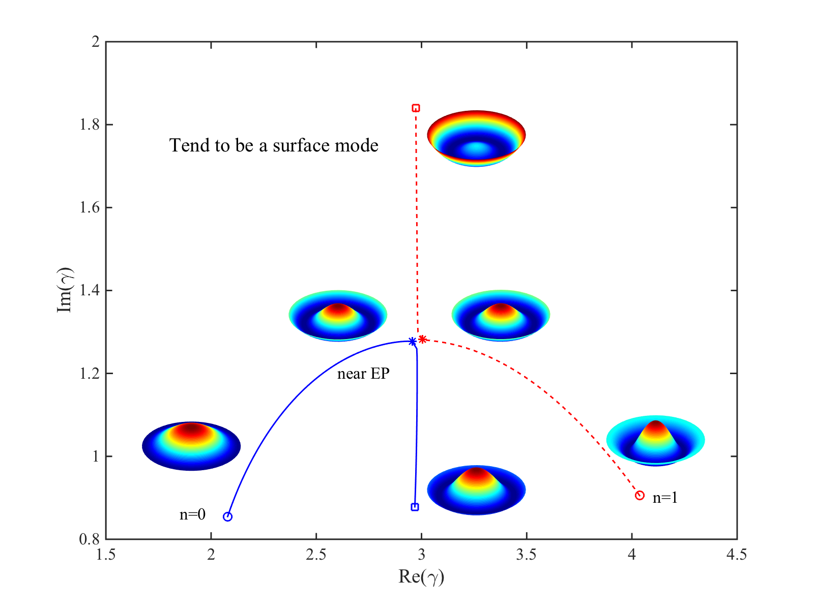
Figure 7: (Color online) Eigenvalue trajectories passing near the first EP as a function of m(β0)𝑚subscript𝛽0\Im m(\beta_{0}). e(β0)=0.09935>e(βEP)𝑒subscript𝛽00.09935𝑒subscript𝛽EP\Re e(\beta_{0})=0.09935>\Re e(\beta_{\text{EP}}). m(β0)=00.05𝑚subscript𝛽000.05\Im m(\beta_{0})=0-0.05. ‘\circ’, m(β0)=0𝑚subscript𝛽00\Im m(\beta_{0})=0; ‘\square’, m(β0)=0.05𝑚subscript𝛽00.05\Im m(\beta_{0})=0.05; and ‘\ast’ refers to near m(βEP)𝑚subscript𝛽EP\Im m(\beta_{\text{EP}}). m=0𝑚0m=0.

where all the elements are complex. A corresponding physical problem can be found in Ref. [34]. The eigenvalues of 𝖧𝖧\mathsf{H} are

γ1,2=12(α1+α2±R),R=(α1α2)2+4λ2c2).\gamma_{1,2}=\frac{1}{2}(\alpha_{1}+\alpha_{2}\pm R),\;\;R=\sqrt{(\alpha_{1}-\alpha_{2})^{2}+4\lambda^{2}c^{2}}). (16)

At the EPs, λEPs=±(α1α2)/(2c)subscript𝜆EPsplus-or-minussubscript𝛼1subscript𝛼22𝑐\lambda_{\text{EPs}}=\pm(\alpha_{1}-\alpha_{2})/(2c), R=0𝑅0R=0, the two eigenvalues coalesce γ1,2=12(α1+α2)subscript𝛾1212subscript𝛼1subscript𝛼2\gamma_{1,2}=\frac{1}{2}(\alpha_{1}+\alpha_{2}), the corresponding eigenvectors also coalesce 𝐱1,2=C[1,j]subscript𝐱12𝐶1𝑗\mathbf{x}_{1,2}=C[1,j] or 𝐱1,2=C[1,j]subscript𝐱12𝐶1𝑗\mathbf{x}_{1,2}=C[1,-j]. When R0𝑅0R\neq 0, the eigenvalues avoided crossing as a function of λ𝜆\lambda. Avoided crossings of eigenvalues have been found in the area of structural dynamics[35, 36, 37, 38] and related to mode localisation in disordered structures[39, 40, 41].

The eigenvalue trajectories in the vicinity of the first EP (βBP=0.099346+0.042653jsubscript𝛽BP0.0993460.042653𝑗\beta_{\text{BP}}=0.099346+0.042653j) is shown in Fig. 7 as a function of m(β0)𝑚subscript𝛽0\Im m(\beta_{0}), when e(β0)=0.09935>e(βEP)𝑒subscript𝛽00.09935𝑒subscript𝛽EP\Re e(\beta_{0})=0.09935>\Re e(\beta_{\text{EP}}) is fixed. The eigenfunctions at some selected β0subscript𝛽0\beta_{0} are also plotted. As m(β0)𝑚subscript𝛽0\Im m(\beta_{0}) increase, the imaginary parts of the eigenvalues of mode n=0𝑛0n=0 and those of mode n=1𝑛1n=1 increase until β0subscript𝛽0\beta_{0} approaches the EP, where the eigenvalues form an avoided crossing and the eigenfunctions mix strongly. With a further increase of m(β0)𝑚subscript𝛽0\Im m(\beta_{0}), mode n=1𝑛1n=1 turns to be a surface mode which is localized near the guide wall as mentioned in section 2.1, and mode n=0𝑛0n=0 turn to a mode which resembles mode n=1𝑛1n=1. The modes exhibit a similar behavior as we plot the eigenvalue trajectories as a function of m(β0)𝑚subscript𝛽0\Im m(\beta_{0}), when e(β0)=0.09933<e(βEP)𝑒subscript𝛽00.09933𝑒subscript𝛽EP\Re e(\beta_{0})=0.09933<\Re e(\beta_{\text{EP}}) is fixed. The only difference is that it is mode n=0𝑛0n=0 turn to be a surface mode and mode n=1𝑛1n=1 return to a mode which resembles mode n=1𝑛1n=1.

It needs to stress that the mode localisation mentioned above is explained as a ”resonance trapping” effect[34], and is different from these studied in Ref. [39, 40, 41] which are due to disorder effects.

2.4 Riemann surfaces

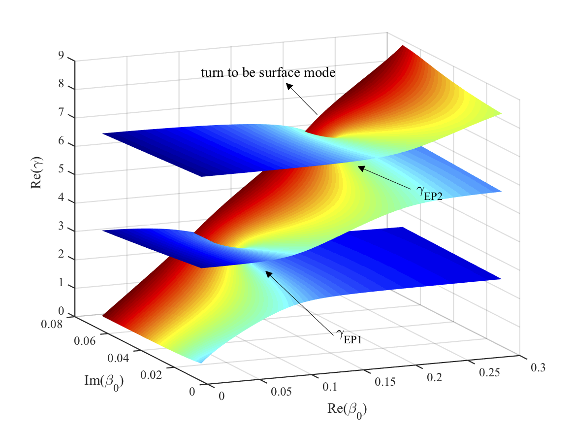
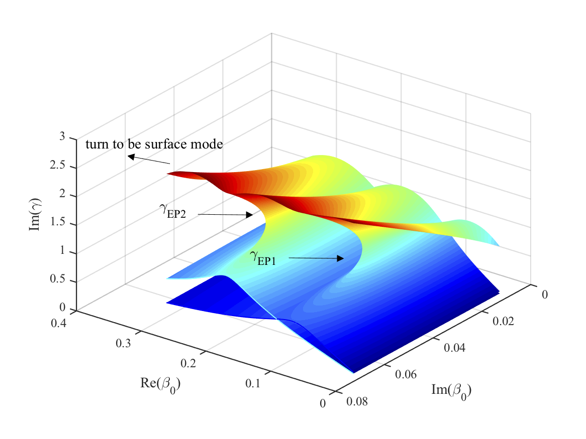
Another way to illustrate the structures of eigenvalues in the vicinities of EPs and the connections between EPs and avoided crossings is to plot the Riemann surface of eigenvalues over β0subscript𝛽0\beta_{0} surface as shown in Figs. 8 and 9 for the first three modes. The values at the first two EPs γEP1subscript𝛾EP1\gamma_{\text{EP1}} and γEP2subscript𝛾EP2\gamma_{\text{EP2}} are pointed out in the figures. Modes with higher circumferential modal order (m>1𝑚1m>1) or higher radial mode order (n2𝑛2n\geq 2) exhibit similar characteristics.

Refer to caption
Figure 8: (Color online) Riemann surfaces of the eigenvalues as a function of admittance β0subscript𝛽0\beta_{0}. Real part of the eigenvalues. The first two EPs are shown. m=0𝑚0m=0.
Refer to caption
Figure 9: (Color online) Riemann surfaces of the eigenvalues as functions of admittance β0subscript𝛽0\beta_{0}. Imaginary part of the eigenvalues. The first two EPs are shown. It is noted that to see more clearly the structures of the Riemann surfaces, the imaginary parts are shown in different viewpoint. m=0𝑚0m=0.

It is well known that mode eigenvalues can vary continuously from one mode to another with continuous varying impedance. This can also be seen from the Riemann surfaces in Figs. 8 and 9. The branch cuts separating one mode from another is arbitrary. When surface modes are present, it is not easy to find unambiguous branch cuts to distinguish the modes. In this paper, we define the mode index n=0, 1,𝑛01n=0,\;1,\cdots, according to the ascending order of the real parts of eigenvalues.

2.5 Self-nonorthogonality Kpsubscript𝐾𝑝K_{p} and mutual-nonorthogonality Sijsubscript𝑆𝑖𝑗S_{ij}

Inspired by the coalescence of eigenfunctions between two neighbour modes and orthogonality between left and right eigenfunctions of the coalescent modes at an EP, we define two quantities: self-nonorthogonality Kp,nsubscript𝐾𝑝𝑛K_{p,n} and mutual-nonorthogonality Sijsubscript𝑆𝑖𝑗S_{ij}

Kp,n=sϕ~nϕ~n𝑑ssφ~nφ~n𝑑ssϕ~nφ~n𝑑s,Kp,n=Kp,n(Kp,n),formulae-sequencesubscriptsuperscript𝐾𝑝𝑛subscript𝑠subscript~italic-ϕ𝑛subscriptsuperscript~italic-ϕ𝑛differential-d𝑠subscript𝑠subscript~𝜑𝑛subscriptsuperscript~𝜑𝑛differential-d𝑠subscript𝑠subscript~italic-ϕ𝑛subscriptsuperscript~𝜑𝑛differential-d𝑠subscript𝐾𝑝𝑛subscriptsuperscript𝐾𝑝𝑛superscriptsuperscriptsubscript𝐾𝑝𝑛K^{\prime}_{p,n}=\frac{\sqrt{\int_{s}\tilde{\phi}_{n}\tilde{\phi}^{*}_{n}ds\int_{s}\tilde{\varphi}_{n}\tilde{\varphi}^{*}_{n}ds}}{\int_{s}\tilde{\phi}_{n}\tilde{\varphi}^{*}_{n}ds},\;\;K_{p,n}=K^{\prime}_{p,n}*(K_{p,n}^{\prime})^{*}, (17)
Sij=sϕ~iϕ~j𝑑ssϕ~iϕ~i𝑑ssϕ~jϕ~j𝑑s=sϕi(r,θ)ϕj(r,θ)𝑑s,subscript𝑆𝑖𝑗subscript𝑠subscript~italic-ϕ𝑖subscriptsuperscript~italic-ϕ𝑗differential-d𝑠subscript𝑠subscript~italic-ϕ𝑖subscriptsuperscript~italic-ϕ𝑖differential-d𝑠subscript𝑠subscript~italic-ϕ𝑗superscriptsubscript~italic-ϕ𝑗differential-d𝑠subscript𝑠subscriptitalic-ϕ𝑖𝑟𝜃subscriptsuperscriptitalic-ϕ𝑗𝑟𝜃differential-d𝑠S_{ij}=\frac{\int_{s}\tilde{\phi}_{i}\tilde{\phi}^{*}_{j}ds}{\sqrt{\int_{s}\tilde{\phi}_{i}\tilde{\phi}^{*}_{i}ds\int_{s}\tilde{\phi}_{j}\tilde{\phi}_{j}^{*}ds}}=\int_{s}\phi_{i}(r,\theta)\phi^{*}_{j}(r,\theta)ds, (18)

to measure the nonorthogonality between left and right eigenfunctions of individual mode n𝑛n and nonorthogonality between modes i𝑖i and j𝑗j in the whole complex impedance (admittance) plane, respectively. It is noted that Kpsubscript𝐾𝑝K_{p} has been proposed by Petermann[42] for explaining the discrepancy between the theoretically expected natural line-width using the Schawlow-Townes formula and the experimental measured enhanced line-width of a gain-guided single mode semiconductor laser.

Two opposite limiting cases can be identified in the complex β0subscript𝛽0\beta_{0} plane:

Case 1: The boundary conditions are non-dissipation, i.e., acoustic rigid, pressure-release, and purely reactive impedance. Modes are mutual-orthogonal, i.e., sϕ~iϕ~j𝑑s=0subscript𝑠subscript~italic-ϕ𝑖subscriptsuperscript~italic-ϕ𝑗differential-d𝑠0\int_{s}\tilde{\phi}_{i}\tilde{\phi}^{*}_{j}ds=0, left eigenfunctions φ~nsubscript~𝜑𝑛\tilde{\varphi}_{n} are equal to right eigenfunctions ϕ~nsubscript~italic-ϕ𝑛\tilde{\phi}_{n}. In this case, Sij=0subscript𝑆𝑖𝑗0S_{ij}=0 and Kp=1subscript𝐾𝑝1K_{p}=1.

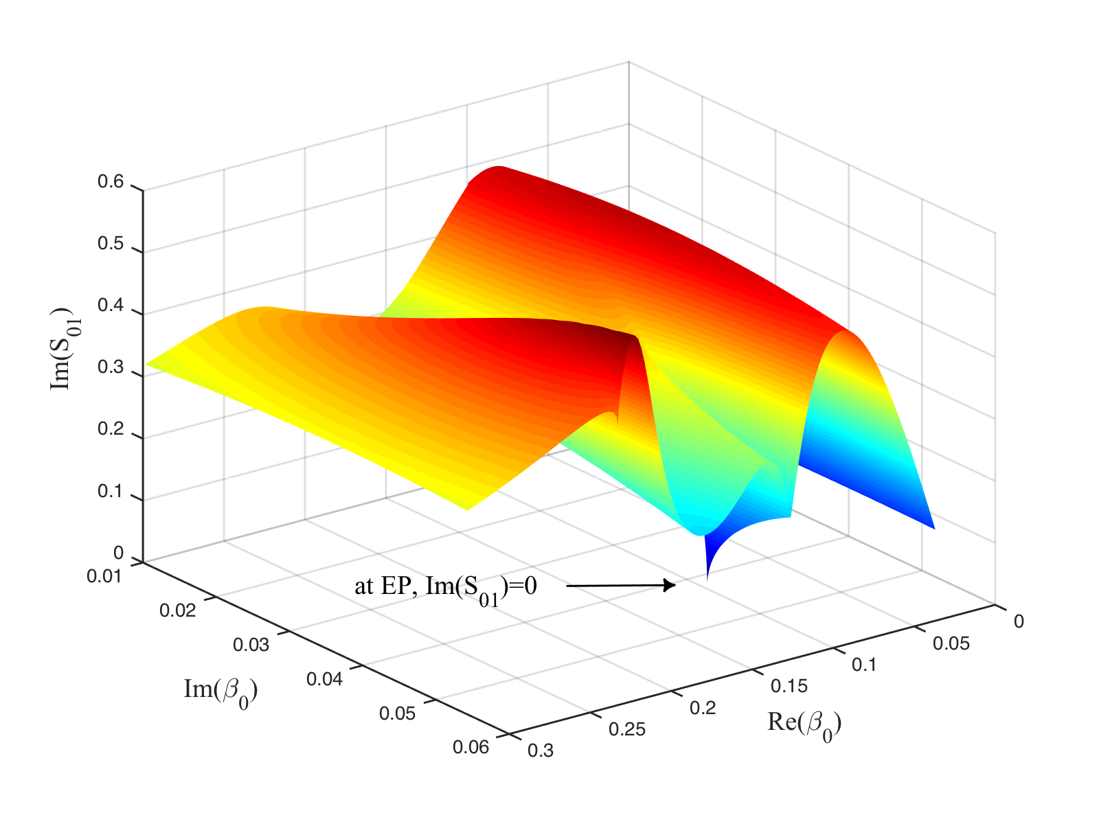
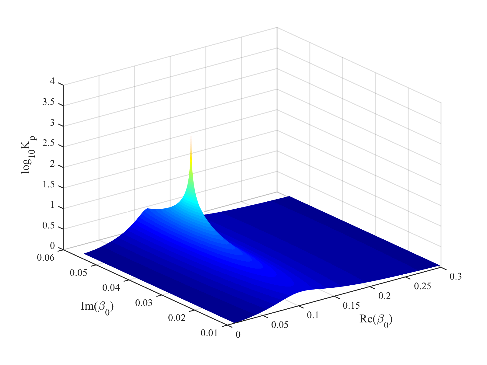
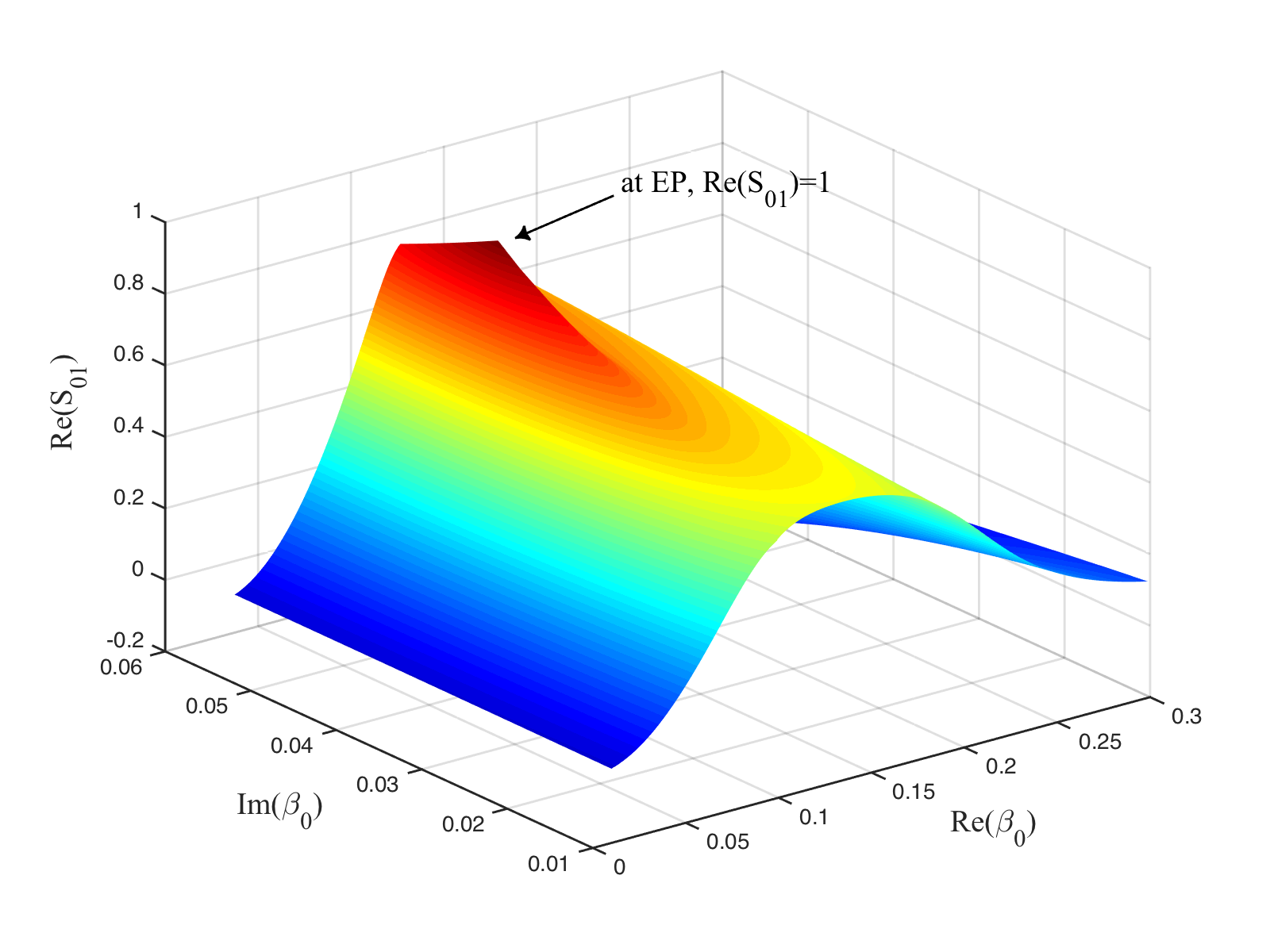
Case 2: At Cremer’s optimum impedances or EPs. Eigenfunctions coalesce between a pair of neighbour modes; Left and right eigenfunctions are self-orthogonal sϕ~nφ~n𝑑s=0subscript𝑠subscript~italic-ϕ𝑛subscriptsuperscript~𝜑𝑛differential-d𝑠0\int_{s}\tilde{\phi}_{n}\tilde{\varphi}^{*}_{n}ds=0, therefore Kpsubscript𝐾𝑝K_{p}\to\infty. In Figs. 10 and 11, we plot Sijsubscript𝑆𝑖𝑗S_{ij} for i=0𝑖0i=0 and j=1𝑗1j=1, and Kpsubscript𝐾𝑝K_{p} for n=0𝑛0n=0 vary over the complex β0subscript𝛽0\beta_{0} plane. It is shown clearly that at βCremersubscript𝛽Cremer\beta_{\text{Cremer}}(βEPsubscript𝛽EP\beta_{\text{EP}})=0.099346+0.042653jabsent0.0993460.042653𝑗=0.099346+0.042653j, S01=1subscript𝑆011S_{01}=1 and Kp,0=6000subscript𝐾𝑝06000K_{p,0}=6000 and tend to be infinite. Varying along an arbitrary path in the complex β0subscript𝛽0\beta_{0} plane, Kpsubscript𝐾𝑝K_{p} and Sijsubscript𝑆𝑖𝑗S_{ij} varies between the two opposite extremes.
Refer to caption
Refer to caption
Figure 10: (Color online) Real and imaginary parts of mutual-nonorthogonality S01subscript𝑆01S_{01} over the complex β0subscript𝛽0\beta_{0} plane. It is noted that for seeing clearly m(S01)=0𝑚subscript𝑆010\Im m(S_{01})=0 at the first EP, we set x-axis (e(β0)𝑒subscript𝛽0\Re e(\beta_{0})) values decrease from left to right, and y-axis (m(β0)𝑚subscript𝛽0\Im m(\beta_{0})) values decrease from front to back.
Refer to caption
Figure 11: (Color online) Self-nonorthogonality log(Kp)10{}_{10}(K_{p}) over the complex β0subscript𝛽0\beta_{0} plane for the first mode n=0𝑛0n=0. m=0𝑚0m=0.

3 Effects of Kpsubscript𝐾𝑝K_{p} and Sijsubscript𝑆𝑖𝑗S_{ij} in sound power attenuation

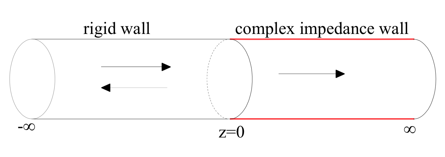
In this section, we will give a simple example to illustrate the important roles of Kpsubscript𝐾𝑝K_{p} and Sijsubscript𝑆𝑖𝑗S_{ij} in sound power attenuation. As shown in Fig. 12, an infinite, cylindrical waveguide with circular cross-section is considered. The left half semi-infinite wall (z<0𝑧0z<0) is rigid and the right half semi-infinite wall (z>0𝑧0z>0) is assumed as complex uniform impedance boundary conditions.
Refer to caption
Figure 12: (Color online) Configuration of the example. The z𝑧z-coordinate is aligned with the centre axis of the cylindrical waveguide. The left half semi-infinite wall (z<0𝑧0z<0) is rigid and the right half semi-infinite wall (z>0𝑧0z>0) is assumed as complex impedance boundary conditions.

The sound pressure satisfies the Helmholtz equation

2p+2pz2+K2p=0,subscriptsuperscript2bottom𝑝superscript2𝑝superscript𝑧2superscript𝐾2𝑝0\nabla^{2}_{\bot}p+\frac{\partial^{2}p}{\partial z^{2}}+K^{2}p=0, (19)

where

2=1rr(rr)+1r22θ2,subscriptsuperscript2bottom1𝑟𝑟𝑟𝑟1superscript𝑟2superscript2superscript𝜃2\nabla^{2}_{\bot}=\frac{1}{r}\frac{\partial}{\partial r}(r\frac{\partial}{\partial r})+\frac{1}{r^{2}}\frac{\partial^{2}}{\partial\theta^{2}}, (20)

and the boundary condition

pr=Yp,atr=1,formulae-sequence𝑝𝑟𝑌𝑝at𝑟1\frac{\partial p}{\partial r}=Yp,\;\;\mathrm{at}\;\;r=1, (21)

where K=ωR/c0𝐾𝜔𝑅subscript𝑐0K=\omega R/c_{0} refers to the dimensionless wave number, Y=jKβ0𝑌𝑗𝐾subscript𝛽0Y=-jK\beta_{0}, and β0subscript𝛽0\beta_{0} is the wall admittance. Pressures and lengths are respectively divided by ρ0c02subscript𝜌0superscriptsubscript𝑐02\rho_{0}c_{0}^{2} and R𝑅R (the duct radius) and become dimensionless variables, where ρ0subscript𝜌0\rho_{0} and c0subscript𝑐0c_{0} refer to ambient density and speed of sound in air, respectively. Rigid muilti-modes are incident from -\infty. Because the wall impedance is circumferentially uniform, eigenfunctions are decoupled in the circumferential direction. Without loss of generality, we consider only circumferential mode m=0𝑚0m=0.

Sound pressure in the semi-infinite WIBC is expanded over right normalized eigenfunctions 𝚽(r)=[ϕ0,ϕ1,,ϕn,,ϕN]T𝚽𝑟superscriptsubscriptitalic-ϕ0subscriptitalic-ϕ1subscriptitalic-ϕ𝑛subscriptitalic-ϕ𝑁𝑇\mathbf{\Phi}(r)=[\phi_{0},\phi_{1},\cdots,\phi_{n},\cdots,\phi_{N}]^{T}

p(r,z)=𝚽T𝖤l(z)𝐂,𝑝𝑟𝑧superscript𝚽𝑇subscript𝖤𝑙𝑧𝐂p(r,z)=\mathbf{\Phi}^{T}\mathsf{E}_{l}(z)\mathbf{C}, (22)

where 𝐂𝐂\mathbf{C} is an amplitude vector of dimension N𝑁N, 𝖤l(z)subscript𝖤𝑙𝑧\mathsf{E}_{l}(z) is a diagonal matrix with exp(jKnz)𝑗subscript𝐾𝑛𝑧\exp(-jK_{n}z) on the main diagonal, with Kn=K2γn2subscript𝐾𝑛superscript𝐾2superscriptsubscript𝛾𝑛2K_{n}=\sqrt{K^{2}-\gamma_{n}^{2}}. ϕnsubscriptitalic-ϕ𝑛\phi_{n} and γnsubscript𝛾𝑛\gamma_{n} are defined in Eqs. (1, 2). "T"superscript"𝑇""^{T}" refers to transpose. N𝑁N refers to the truncation of the expansion. The eigenfunctions are normalized as defined in Eq. (11). It is noted that although there is no mathematical theorem to guarantee the completeness of ϕnsubscriptitalic-ϕ𝑛\phi_{n}, n=0𝑛0n=0-\infty, however, except at the infinite exceptional points, we found numerically that the expansion is convergent, in general, in the whole complex plane.

The continuities of pressure and axial particle velocity at z=0𝑧0z=0 lead to

𝚿T(𝐀+𝐁)superscript𝚿𝑇𝐀𝐁\displaystyle\mathbf{\Psi}^{T}(\mathbf{A}+\mathbf{B}) =𝚽T𝐂,absentsuperscript𝚽𝑇𝐂\displaystyle=\mathbf{\Phi}^{T}\mathbf{C}, (23)
𝚿T𝖪r(𝐀𝐁)superscript𝚿𝑇subscript𝖪𝑟𝐀𝐁\displaystyle\mathbf{\Psi}^{T}\mathsf{K}_{r}(\mathbf{A}-\mathbf{B}) =𝚽T𝖪l𝐂,absentsuperscript𝚽𝑇subscript𝖪𝑙𝐂\displaystyle=\mathbf{\Phi}^{T}\mathsf{K}_{l}\mathbf{C}, (24)

where 𝚿=[ψ0,ψ1,,ψn,,ψN]T𝚿superscriptsubscript𝜓0subscript𝜓1subscript𝜓𝑛subscript𝜓𝑁𝑇\mathbf{\Psi}=[\psi_{0},\psi_{1},\cdots,\psi_{n},\cdots,\psi_{N}]^{T}, 𝖪rsubscript𝖪𝑟\mathsf{K}_{r} and 𝖪lsubscript𝖪𝑙\mathsf{K}_{l} are diagonal matrices with the axial wavenumbers K2αn2superscript𝐾2superscriptsubscript𝛼𝑛2\sqrt{K^{2}-\alpha_{n}^{2}} and K2γn2superscript𝐾2superscriptsubscript𝛾𝑛2\sqrt{K^{2}-\gamma_{n}^{2}} on their main diagonal, respectively. ψnsubscript𝜓𝑛\psi_{n} and αnsubscript𝛼𝑛\alpha_{n} are the normalised eigenfunctions and eigenvalues of modes in the semi-infinite waveguide with rigid boundary conditions. 𝐀𝐀\mathbf{A} and 𝐁𝐁\mathbf{B} are the amplitude vectors of incident and reflected modes.

Projecting Eq. (23) over the left normalised eigenfunctions 𝝋=[φ0,φ1,,φn,,φN]Tsuperscript𝝋superscriptsubscript𝜑0subscript𝜑1subscript𝜑𝑛subscript𝜑𝑁absent𝑇\boldsymbol{\varphi}^{*}=[\varphi_{0},\varphi_{1},\cdots,\varphi_{n},\cdots,\varphi_{N}]^{*T}, and Eq. (24) over the normalised rigid eigenfunctions 𝚿superscript𝚿\mathbf{\Psi}^{*}, we obtain

𝖦𝖦\displaystyle\mathsf{G} =(𝖪r+𝖥T𝖪l𝖪p𝖥)1(𝖪r𝖥T𝖪l𝖪p𝖥),absentsuperscriptsubscript𝖪𝑟superscript𝖥𝑇subscript𝖪𝑙superscriptsubscript𝖪𝑝𝖥1subscript𝖪𝑟superscript𝖥𝑇subscript𝖪𝑙superscriptsubscript𝖪𝑝𝖥\displaystyle=(\mathsf{K}_{r}+\mathsf{F}^{T}\mathsf{K}_{l}\mathsf{K}_{p}^{\prime}\mathsf{F})^{-1}(\mathsf{K}_{r}-\mathsf{F}^{T}\mathsf{K}_{l}\mathsf{K}_{p}^{\prime}\mathsf{F}),
𝐁𝐁\displaystyle\mathbf{B} =𝖦𝐀,absent𝖦𝐀\displaystyle=\mathsf{G}\mathbf{A}, (25)
𝐂𝐂\displaystyle\mathbf{C} =𝖪p𝖥(𝖨+𝖦)𝐀,absentsuperscriptsubscript𝖪𝑝𝖥𝖨𝖦𝐀\displaystyle=\mathsf{K}_{p}^{\prime}\mathsf{F}(\mathsf{I}+\mathsf{G})\mathbf{A},

where

𝖥=01𝝋𝚿Tr𝑑r,𝖥superscriptsubscript01superscript𝝋superscript𝚿𝑇𝑟differential-d𝑟\mathsf{F}=\int_{0}^{1}\boldsymbol{\varphi}^{*}\mathbf{\Psi}^{T}rdr, (26)

describes the couplings between the eigenfunctions of modes in the semi-infinite waveguides of rigid wall and complex impedance wall, respectively. 𝖪psubscriptsuperscript𝖪𝑝\mathsf{K}^{\prime}_{p} is a diagonal matrix with Kp,nsubscriptsuperscript𝐾𝑝𝑛K^{\prime}_{p,n} defined in Eq. (17) on the main diagonal.

Sound power in the semi-infinite WIBC is

W𝑊\displaystyle W =12e{01p(r,θ)vz(r,θ)r𝑑r}absent12𝑒superscriptsubscript01𝑝𝑟𝜃superscriptsubscript𝑣𝑧𝑟𝜃𝑟differential-d𝑟\displaystyle=\frac{1}{2}\Re e\{\int_{0}^{1}p(r,\theta)v_{z}^{*}(r,\theta)rdr\} (27)
=12e[𝐀T(𝖨+𝖦)T𝖥𝖤l(z)𝖪p𝖲ij(𝖪p)(𝖪l/K)𝖤l(z)𝖥(𝖨+𝖦)T𝐀]absent12𝑒delimited-[]superscript𝐀𝑇superscript𝖨𝖦𝑇subscript𝖥𝖤𝑙𝑧subscriptsuperscript𝖪𝑝subscript𝖲𝑖𝑗superscriptsuperscriptsubscript𝖪𝑝subscript𝖪𝑙𝐾superscriptsubscript𝖤𝑙𝑧superscript𝖥superscript𝖨𝖦absent𝑇superscript𝐀\displaystyle=\frac{1}{2}\Re e[\mathbf{A}^{T}(\mathsf{I}+\mathsf{G})^{T}\mathsf{F}\mathsf{E}_{l}(z)\mathsf{K}^{\prime}_{p}\mathsf{S}_{ij}(\mathsf{K}_{p}^{\prime})^{*}(\mathsf{K}_{l}/K)\mathsf{E}_{l}^{*}(z)\mathsf{F}^{*}(\mathsf{I}+\mathsf{G})^{*T}\mathbf{A}^{*}]
=12e[i=j|Ci|2Kp,iKl,iKem(Kl,i)z]sum of sound power in individual mode+12e[ijCiCjKp,iSij(Kp,j)Kl,jKej(Kl,iKl,j)z]sum of cross power,absentsubscript12𝑒delimited-[]subscript𝑖𝑗superscriptsuperscriptsubscript𝐶𝑖2subscript𝐾𝑝𝑖superscriptsubscript𝐾𝑙𝑖𝐾superscript𝑒𝑚subscript𝐾𝑙𝑖𝑧sum of sound power in individual modesubscript12𝑒delimited-[]subscript𝑖𝑗superscriptsubscript𝐶𝑖superscriptsubscript𝐶𝑗subscriptsuperscript𝐾𝑝𝑖subscript𝑆𝑖𝑗superscriptsuperscriptsubscript𝐾𝑝𝑗superscriptsubscript𝐾𝑙𝑗𝐾superscript𝑒𝑗subscript𝐾𝑙𝑖superscriptsubscript𝐾𝑙𝑗𝑧sum of cross power\displaystyle=\underbrace{\frac{1}{2}\Re e[\sum_{i=j}|C_{i}^{\prime}|^{2}K_{p,i}\frac{K_{l,i}^{*}}{K}e^{-\Im m(K_{l,i})z}]}_{\text{sum of sound power in individual mode}}+\underbrace{\frac{1}{2}\Re e[\sum_{i\neq j}C_{i}^{\prime}C_{j}^{\prime*}K^{\prime}_{p,i}S_{ij}(K_{p,j}^{\prime})^{*}\frac{K_{l,j}^{*}}{K}e^{-j(K_{l,i}-K_{l,j}^{*})z}]}_{\text{sum of cross power}},

where

𝖢=𝖥(𝖨+𝖦)𝐀,superscript𝖢𝖥𝖨𝖦𝐀\mathsf{C}^{\prime}=\mathsf{F}(\mathsf{I}+\mathsf{G})\mathbf{A}, (28)

is a column vector, Ci(j)subscriptsuperscript𝐶𝑖𝑗C^{\prime}_{i(j)} are the elements of 𝖢superscript𝖢\mathsf{C}^{\prime}, 𝖲ijsubscript𝖲𝑖𝑗\mathsf{S}_{ij} is a matrix, its elements Sijsubscript𝑆𝑖𝑗S_{ij} are defined in Eq. (18), Kl,i(j)subscript𝐾𝑙𝑖𝑗K_{l,i(j)} are the elements i(j)𝑖𝑗i(j) of the wavenumber matrix 𝖪lsubscript𝖪𝑙\mathsf{K}_{l}.

Equation (27) clearly shows that the sound power are mainly decided not only by the individual mode attenuation factors 𝖤l(z)subscript𝖤𝑙𝑧\mathsf{E}_{l}(z) (diagonal matrix with ejKl,izsuperscript𝑒𝑗subscript𝐾𝑙𝑖𝑧e^{-jK_{l,i}z} on the main diagonal), but also by self-nonorthogonality Kpsubscript𝐾𝑝K_{p} and mutual-nonorthogonality Sijsubscript𝑆𝑖𝑗S_{ij}, and 𝖥𝖥\mathsf{F} which describes the couplings between eigenfunctions of modes in the semi-infinite waveguides of rigid wall and complex impedance wall.

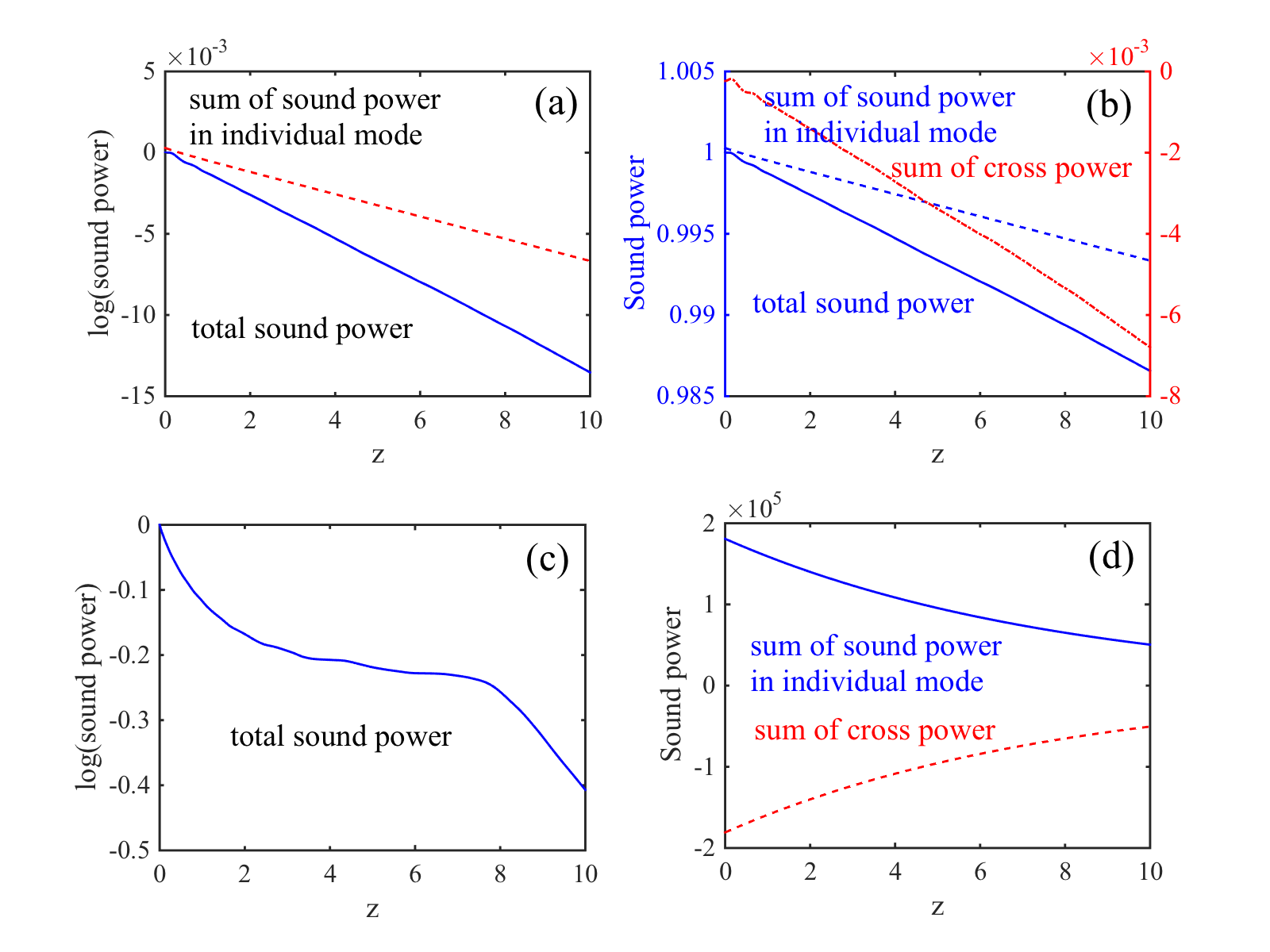
In Fig. 13, we show sound power as a function of z𝑧z for two two cases: Case 1, Z=0.1j𝑍0.1𝑗Z=0.1-j in which the dissipation in the boundary wall is less important; Case 2, β0=0.0993+0.0427subscript𝛽00.09930.0427\beta_{0}=0.0993+0.0427 which is close to the first EP (m=0𝑚0m=0), the boundary wall is very dissipative. Rigid multi-modes with coefficient
Refer to caption
Figure 13: (Color online) Sound power as a function of z𝑧z. (a) Total sound power (solid line) and sum of sound power in individual mode (dashed line) for case 1: Z=0.1j𝑍0.1𝑗Z=0.1-j. (Sound power is in logarithm scale.) (b) Total sound power (solid line), sum of sound power in individual mode (dashed line) and sum of cross power (dash-dot line) for case 1: Z=0.1j𝑍0.1𝑗Z=0.1-j. (Sound power is in linear scale.) (c) Total sound power for case 2: β0=0.0993+0.0427jsubscript𝛽00.09930.0427𝑗\beta_{0}=0.0993+0.0427j. (Sound power is in logarithm scale.) (d) Sum of sound power in individual mode (solid line) and sum of cross power for case 2: β0=0.0993+0.0427jsubscript𝛽00.09930.0427𝑗\beta_{0}=0.0993+0.0427j. (Sound power is in linear scale.) K=30𝐾30K=30.
Refer to caption
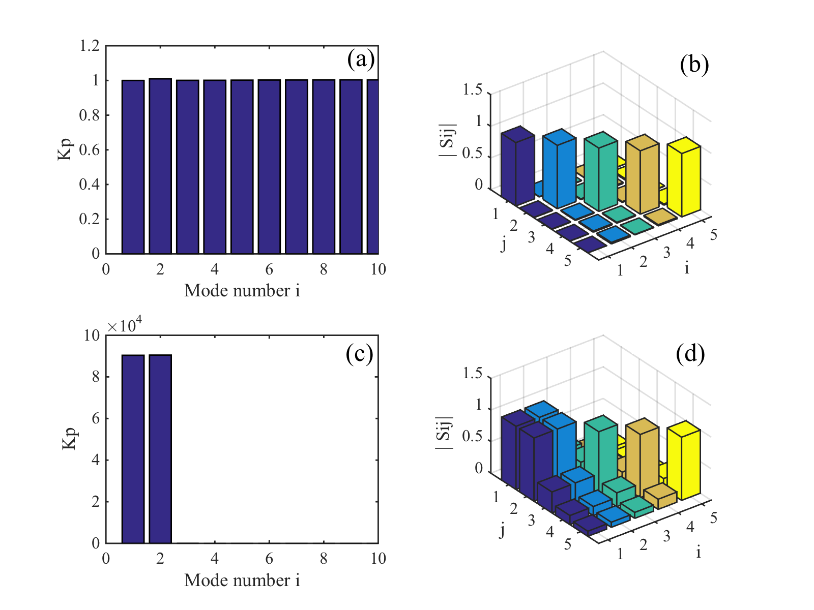
Figure 14: (Color online) Self-nonorthogonality Kpsubscript𝐾𝑝K_{p} and mutual-nonorthogonality Sijsubscript𝑆𝑖𝑗S_{ij}. (a) Kpsubscript𝐾𝑝K_{p} for case 1, Z=0.1j𝑍0.1𝑗Z=0.1-j. (b) Sijsubscript𝑆𝑖𝑗S_{ij} for case 1, Z=0.1j𝑍0.1𝑗Z=0.1-j. (c) Kpsubscript𝐾𝑝K_{p} for case 2, β0=0.0993+0.0427jsubscript𝛽00.09930.0427𝑗\beta_{0}=0.0993+0.0427j. Sijsubscript𝑆𝑖𝑗S_{ij} for case 2, β0=0.0993+0.0427jsubscript𝛽00.09930.0427𝑗\beta_{0}=0.0993+0.0427j. K=30𝐾30K=30.
Ai=01ψiφ0r𝑑r=01ψi1Λ0(J0(γ0r)J0(γ0))r𝑑r,subscript𝐴𝑖superscriptsubscript01subscript𝜓𝑖subscript𝜑0𝑟differential-d𝑟superscriptsubscript01subscript𝜓𝑖1subscriptΛ0superscriptsubscript𝐽0subscript𝛾0𝑟subscript𝐽0subscript𝛾0𝑟differential-d𝑟A_{i}=\int_{0}^{1}\psi_{i}\varphi_{0}rdr=\int_{0}^{1}\psi_{i}\frac{1}{\sqrt{\Lambda_{0}}}(\frac{J_{0}(\gamma_{0}r)}{J_{0}(\gamma_{0})})^{*}rdr, (29)

are incident, where “” refers to complex conjugate, i=050𝑖050i=0-50 are incident rigid mode index. J0subscript𝐽0J_{0} is zero order Bessel function. Without loss of generality, we use K=30𝐾30K=30, which is a typically industrial value in the lined intakes of an aeroengine.

For case 1, small dissipation is included, Kpsubscript𝐾𝑝K_{p} are approximately equal to 111 for all modes as shown in Fig. 14 (a). Modes are approximately mutual-orthogonal. Sijsubscript𝑆𝑖𝑗S_{ij} (ij𝑖𝑗i\neq j) are approximately equal to zero as shown in Fig. 14 (b). The total sound power and the sum of sound power in individual mode decrease exponentially, as we expect intuitively, as shown in Fig. 13 (a). The sum of cross-power is not important as shown in Fig. 13 (b). (For comparison, we plot also in Fig. 13 (b) the total sound power and the sum of sound power in individual mode. Note that they are shown in linear scale.) This conclusion can be also obtained directly from Eq. (27).

However, for case 2 in which the impedance is close to the first EP, the acoustically absorbent material is very dissipative, it is very surprise that the total sound power attenuation curve has a plateau between about z=2𝑧2z=2 and z=8𝑧8z=8 where total sound power almost does not attenuate as shown in Fig. 13 (c). The sum of sound power in individual mode decreases still exponentially (not shown), but with very large amplitude (about 105superscript10510^{5}) as shown in Fig. 13 (d). The sum of cross-power are negative and increases with z𝑧z with almost the same order of amplitude. By these results, we can conclude safely that although Cremer’s optimum impedances give the maximum attenuation for individual mode, however, they stimulate simultaneously very high amplitudes for the corresponding mode, the total sound power attenuation is mainly decided by the sum of sound power in individual mode and the sum of cross power cancel each other out.

This can be explained also by Eq. (27) in which the amplitudes of modes i=0𝑖0i=0 and j=1𝑗1j=1 are extremely larger than these of other modes. The two modes dominate the total sound power, the sum of sound power in individual mode, and the sum of cross power over other modes. The extremely large amplitudes are due to the nearly self-orthogonalities between left and right eigenfunctions of the almost coalescent modes i=0𝑖0i=0 and j=1𝑗1j=1 near the first EP. This can be seen by the Kpsubscript𝐾𝑝K_{p} shown in Fig. 14 (c) whose values are approximately equal to 9×1049superscript1049\times 10^{4} for modes i=0𝑖0i=0 and j=1𝑗1j=1 and are extremely larger than these of other modes. The important effects of cross-power are produced by the mutual-nonorthogonality Sijsubscript𝑆𝑖𝑗S_{ij}. In this case, S01subscript𝑆01S_{01} and S10subscript𝑆10S_{10} are approximately equal to 111 as shown in Fig. 14 (d). Because the two modes i=0𝑖0i=0 and i=1𝑖1i=1 are almost coalescent, Kp,0subscriptsuperscript𝐾𝑝0K^{\prime}_{p,0} and Kp,1subscriptsuperscript𝐾𝑝1K^{\prime}_{p,1} are approximately equal. Similary, C0superscriptsubscript𝐶0C_{0}^{\prime}, K0subscript𝐾0K_{0} are are approximately equal to C1subscriptsuperscript𝐶1C^{\prime}_{1} and K1subscript𝐾1K_{1}, therefore the sum of sound power in individual mode and the sum of cross power cancel each other out.

4 Conclusions

In this paper, we have given new insights into the nonorthogonalities of eigenfunctions in a waveguide with impedance boundary conditions. We have defined two quantities: self-nonorthogonality Kp𝐾𝑝Kp, which measures the nonorthogonality between left and right eigenfunctions of a mode, and mutual-nonorthogonality Sijsubscript𝑆𝑖𝑗S_{ij}, which measures the nonorthogonality between modes i𝑖i and j𝑗j. Two opposite limiting cases are clearly identified in the complex boundary admittance β0subscript𝛽0\beta_{0} plane. One is non-dissipation, i.e., acoustic rigid, pressure-release, and purely reactive impedance. Modes are mutual-orthogonal. Left eigenfunctions are equal to right eigenfunctions. Sij=0subscript𝑆𝑖𝑗0S_{ij}=0 and Kp=1subscript𝐾𝑝1K_{p}=1. The other is Cremer’s optimum impedances which are exceptional points. Both eigenvalues and eigenfunctions coalesce between a pair of neighbour modes i𝑖i and j𝑗j. Left and right eigenfunctions of the coalescent modes are self-orthogonal. In this case, Sij=1subscript𝑆𝑖𝑗1S_{ij}=1 and Kp=subscript𝐾𝑝K_{p}=\infty.

The total sound power in the waveguide is mainly decided by Kpsubscript𝐾𝑝K_{p}, Sijsubscript𝑆𝑖𝑗S_{ij}, besides the exponential attenuation factors ejKlzsuperscript𝑒𝑗subscript𝐾𝑙𝑧e^{-jK_{l}z}. We have shown that although Cremer’s optimum impedances give the maximum attenuation for individual mode, however, they simultaneously stimulate very high amplitudes for the corresponding mode. When the acoustically absorbent materials are very dissipative, the total sound power attenuation is mainly decided by the cancel each other out between the sum of sound power in individual mode and the sum of cross power.

Appendix A Adjoint eigenvalue problem and bi-orthogonal relation

We consider an operator =2+γmn2subscriptsuperscript2bottomsuperscriptsubscript𝛾𝑚𝑛2\mathscr{L}=\nabla^{2}_{\bot}+\gamma_{mn}^{2}, the eigenvalue problem defined by Eqs. (1) and (2) can be rewritten as

ϕ~mn=0,subscript~italic-ϕ𝑚𝑛0\mathscr{L}\tilde{\phi}_{mn}=0, (30)

with the boundary condition

𝒢ϕ~mn=0,atr=1,formulae-sequence𝒢subscript~italic-ϕ𝑚𝑛0at𝑟1\mathscr{G}\tilde{\phi}_{mn}=0,\;\text{at}\;r=1, (31)

where 𝒢=/rY𝒢𝑟𝑌\mathscr{G}=\partial/\partial r-Y. By introducing a function φ~~𝜑\tilde{\varphi} which satisfies

sφ~mnϕ~mn𝑑ssubscript𝑠subscriptsuperscript~𝜑superscript𝑚superscript𝑛subscript~italic-ϕ𝑚𝑛differential-d𝑠\displaystyle\int_{s}\tilde{\varphi}^{*}_{m^{\prime}n^{\prime}}\mathscr{L}\tilde{\phi}_{mn}ds =sφ~mn(2+γmn2)ϕ~mn𝑑sabsentsubscript𝑠subscriptsuperscript~𝜑superscript𝑚superscript𝑛subscriptsuperscript2bottomsuperscriptsubscript𝛾𝑚𝑛2subscript~italic-ϕ𝑚𝑛differential-d𝑠\displaystyle=\int_{s}\tilde{\varphi}^{*}_{m^{\prime}n^{\prime}}(\nabla^{2}_{\bot}+\gamma_{mn}^{2})\tilde{\phi}_{mn}ds (32)
=sϕ~mn[2+γmn2]φ~mn𝑑s+(φ~mnϕ~mnrϕ~mnφ~mnr)𝑑Cabsentsubscript𝑠subscript~italic-ϕ𝑚𝑛delimited-[]subscriptsuperscript2bottomsuperscriptsubscript𝛾𝑚𝑛2subscriptsuperscript~𝜑superscript𝑚superscript𝑛differential-d𝑠contour-integralsubscriptsuperscript~𝜑superscript𝑚superscript𝑛subscript~italic-ϕ𝑚𝑛𝑟subscript~italic-ϕ𝑚𝑛subscriptsuperscript~𝜑superscript𝑚superscript𝑛𝑟differential-d𝐶\displaystyle=\int_{s}\tilde{\phi}_{mn}[\nabla^{2}_{\bot}+\gamma_{mn}^{2}]\tilde{\varphi}^{*}_{m^{\prime}n^{\prime}}ds+\oint\left(\tilde{\varphi}^{*}_{m^{\prime}n^{\prime}}\frac{\partial\tilde{\phi}_{mn}}{\partial r}-\tilde{\phi}_{mn}\frac{\partial\tilde{\varphi}^{*}_{m^{\prime}n^{\prime}}}{\partial r}\right)dC (33)
=s(+φ~mn)ϕ~mn𝑑s02πϕ~mn(φ~mnrYφ~mn)𝑑θabsentsubscript𝑠superscriptsuperscriptsubscript~𝜑superscript𝑚superscript𝑛subscript~italic-ϕ𝑚𝑛differential-d𝑠superscriptsubscript02𝜋subscript~italic-ϕ𝑚𝑛superscriptsubscript~𝜑superscript𝑚superscript𝑛𝑟𝑌subscriptsuperscript~𝜑superscript𝑚superscript𝑛differential-d𝜃\displaystyle=\int_{s}(\mathscr{L}^{+}\tilde{\varphi}_{m^{\prime}n^{\prime}})^{*}\tilde{\phi}_{mn}ds-\int_{0}^{2\pi}\tilde{\phi}_{mn}\left(\frac{\partial\tilde{\varphi}_{m^{\prime}n^{\prime}}^{*}}{\partial r}-Y\tilde{\varphi}^{*}_{m^{\prime}n^{\prime}}\right)d\theta
=s(+φ~mn)ϕ~mn𝑑s02πϕ~mn(𝒢+φ~mn),absentsubscript𝑠superscriptsuperscriptsubscript~𝜑superscript𝑚superscript𝑛subscript~italic-ϕ𝑚𝑛differential-d𝑠superscriptsubscript02𝜋subscript~italic-ϕ𝑚𝑛superscriptsuperscript𝒢subscript~𝜑superscript𝑚superscript𝑛\displaystyle=\int_{s}(\mathscr{L}^{+}\tilde{\varphi}_{m^{\prime}n^{\prime}})^{*}\tilde{\phi}_{mn}ds-\int_{0}^{2\pi}\tilde{\phi}_{mn}(\mathscr{G}^{+}\tilde{\varphi}_{m^{\prime}n^{\prime}})^{*},

where

+=2+(γmn2)=2+ϵmn2,𝒢+=/rY,formulae-sequencesuperscriptsubscriptsuperscript2bottomsuperscriptsuperscriptsubscript𝛾𝑚𝑛2subscriptsuperscript2bottomsuperscriptsubscriptitalic-ϵsuperscript𝑚superscript𝑛2superscript𝒢𝑟superscript𝑌\displaystyle\mathscr{L}^{+}=\nabla^{2}_{\bot}+(\gamma_{mn}^{2})^{*}=\nabla^{2}_{\bot}+\epsilon_{m^{\prime}n^{\prime}}^{2},\;\;\;\;\mathscr{G}^{+}=\partial/\partial r-Y^{*}, (34)

we can define the adjoint eigenvalue problem as

+φ~mn=0,superscriptsubscript~𝜑superscript𝑚superscript𝑛0\mathscr{L}^{+}\tilde{\varphi}_{m^{\prime}n^{\prime}}=0, (35)

with the boundary condition

𝒢+φ~mn=0,atr=1.formulae-sequencesuperscript𝒢subscript~𝜑superscript𝑚superscript𝑛0at𝑟1\mathscr{G}^{+}\tilde{\varphi}_{m^{\prime}n^{\prime}}=0,\;\text{at}\;r=1. (36)

Multiplying Eq. (30) by φ~mnsubscriptsuperscript~𝜑superscript𝑚superscript𝑛\tilde{\varphi}^{*}_{m^{\prime}n^{\prime}} and the conjugate of Eq. (35) by ϕ~mnsubscript~italic-ϕ𝑚𝑛\tilde{\phi}_{mn} for different mode γmn2(ϵmn2)subscriptsuperscript𝛾2𝑚𝑛superscriptsubscriptsuperscriptitalic-ϵ2superscript𝑚superscript𝑛\gamma^{2}_{mn}\neq(\epsilon^{2}_{m^{\prime}n^{\prime}})^{*}, i.e., mm𝑚superscript𝑚m\neq m^{\prime} and nn𝑛superscript𝑛n\neq n^{\prime}, and subtracting the results, we obtain

[γmn2(ϵmn2)]sϕ~mnφ~mn𝑑sdelimited-[]superscriptsubscript𝛾𝑚𝑛2superscriptsuperscriptsubscriptitalic-ϵsuperscript𝑚superscript𝑛2subscript𝑠subscript~italic-ϕ𝑚𝑛superscriptsubscript~𝜑superscript𝑚superscript𝑛differential-d𝑠\displaystyle[\gamma_{mn}^{2}-(\epsilon_{m^{\prime}n^{\prime}}^{2})^{*}]\int_{s}\tilde{\phi}_{mn}\tilde{\varphi}_{m^{\prime}n^{\prime}}^{*}ds =s(ϕ~mn2φ~mnφ~mn2ϕ~mn)𝑑sabsentsubscript𝑠subscript~italic-ϕ𝑚𝑛subscriptsuperscript2bottomsubscriptsuperscript~𝜑superscript𝑚superscript𝑛superscriptsubscript~𝜑superscript𝑚superscript𝑛subscriptsuperscript2bottomsubscript~italic-ϕ𝑚𝑛differential-d𝑠\displaystyle=\int_{s}(\tilde{\phi}_{mn}\nabla^{2}_{\bot}\tilde{\varphi}^{*}_{m^{\prime}n^{\prime}}-\tilde{\varphi}_{m^{\prime}n^{\prime}}^{*}\nabla^{2}_{\bot}\tilde{\phi}_{mn})ds (37)
=(ϕ~mnφ~mnrφ~mnϕ~mnr)𝑑Cabsentcontour-integralsubscript~italic-ϕ𝑚𝑛subscriptsuperscript~𝜑superscript𝑚superscript𝑛𝑟subscriptsuperscript~𝜑superscript𝑚superscript𝑛subscript~italic-ϕ𝑚𝑛𝑟differential-d𝐶\displaystyle=\oint\left(\tilde{\phi}_{mn}\frac{\partial\tilde{\varphi}^{*}_{m^{\prime}n^{\prime}}}{\partial r}-\tilde{\varphi}^{*}_{m^{\prime}n^{\prime}}\frac{\partial\tilde{\phi}_{mn}}{\partial r}\right)dC (38)
=02πϕ~mn(φ~mnrYφ~mn)𝑑θabsentsuperscriptsubscript02𝜋subscript~italic-ϕ𝑚𝑛subscriptsuperscript~𝜑superscript𝑚superscript𝑛𝑟𝑌subscriptsuperscript~𝜑superscript𝑚superscript𝑛differential-d𝜃\displaystyle=\int_{0}^{2\pi}\tilde{\phi}_{mn}\left(\frac{\partial\tilde{\varphi}^{*}_{m^{\prime}n^{\prime}}}{\partial r}-Y\tilde{\varphi}^{*}_{m^{\prime}n^{\prime}}\right)d\theta
=0,absent0\displaystyle=0,

where we have used Eq. (36), 𝒢+φ~mn=0superscript𝒢subscript~𝜑𝑚𝑛0\mathscr{G}^{+}\tilde{\varphi}_{mn}=0. Therefore,

sϕ~mnφ~mn𝑑s=0,whenmm,nn.formulae-sequencesubscript𝑠subscript~italic-ϕ𝑚𝑛subscriptsuperscript~𝜑superscript𝑚superscript𝑛differential-d𝑠0formulae-sequencewhen𝑚superscript𝑚𝑛superscript𝑛\int_{s}\tilde{\phi}_{mn}\tilde{\varphi}^{*}_{m^{\prime}n^{\prime}}ds=0,\;\;\text{when}\;m\neq m^{\prime},\;n\neq n^{\prime}. (39)

When the boundary is acoustically rigid (Y=0𝑌0Y=0), pressure release (Z=0𝑍0Z=0), or purely reactive without dissipation (β0=jcsubscript𝛽0𝑗𝑐\beta_{0}=jc, Y=jKβ0=Kc𝑌𝑗𝐾subscript𝛽0𝐾𝑐Y=-jK\beta_{0}=Kc, c𝑐c is real),

+=,𝒢+=𝒢,formulae-sequencesuperscriptsuperscript𝒢𝒢\mathscr{L}^{+}=\mathscr{L},\;\;\mathscr{G}^{+}=\mathscr{G}, (40)

the eigenvalue problem defined by Eqs. (1) and (2) or (30) and (31) is self-adjoint. It is easy to show that γmn2superscriptsubscript𝛾𝑚𝑛2\gamma_{mn}^{2} are real and φ~mn=ϕ~mnsubscript~𝜑𝑚𝑛subscript~italic-ϕ𝑚𝑛\tilde{\varphi}_{mn}=\tilde{\phi}_{mn}.

On the other hand, for all practical problem, β0subscript𝛽0\beta_{0} and therefore Y𝑌Y are complex. Taking the complex conjugate of Eqs. (35) and (36), we obtain

φ~mn=ϕ~mn.subscript~𝜑𝑚𝑛superscriptsubscript~italic-ϕ𝑚𝑛\tilde{\varphi}_{mn}=\tilde{\phi}_{mn}^{*}. (41)

The orthogonal relation (39) is then rewritten as the bi-orthogonality (10)

sϕ~mnφ~mn𝑑s=sϕ~mnϕ~mn𝑑s=0,whenmm,nn.formulae-sequencesubscript𝑠subscript~italic-ϕ𝑚𝑛superscriptsubscript~𝜑superscript𝑚superscript𝑛differential-d𝑠subscript𝑠subscript~italic-ϕ𝑚𝑛subscript~italic-ϕsuperscript𝑚superscript𝑛differential-d𝑠0formulae-sequencewhen𝑚superscript𝑚𝑛superscript𝑛\int_{s}\tilde{\phi}_{mn}\tilde{\varphi}_{m^{\prime}n^{\prime}}^{*}ds=\int_{s}\tilde{\phi}_{mn}\tilde{\phi}_{m^{\prime}n^{\prime}}ds=0,\;\;\text{when}\;m\neq m^{\prime},\;n\neq n^{\prime}. (42)

Appendix B Branch point on the complex admittance plane

We consider the variation of eigenvalues as a function of complex admittance. At some admittances, the eigenvalues of a pair of neighbour modes coalesce to form Branch Points (BP) on the complex admittance plane. At the BP, the dispersion equation (4) has double eigenvalues γBPsubscript𝛾BP\gamma_{\text{BP}}, i.e.

γm0nJm0(γm0n)Jm0(γm0n)|γm0n=γBP\displaystyle\gamma_{m_{0}n}\frac{J^{\prime}_{m_{0}}(\gamma_{m_{0}n})}{J_{m_{0}}(\gamma_{m_{0}n})}\Bigm{|}_{\gamma_{m_{0}n}=\gamma_{\text{BP}}} =jKβBP,absent𝑗𝐾subscript𝛽BP\displaystyle=-jK\beta_{\text{BP}}, (43)
γm0n(γm0nJm0(γm0n)Jm0(γm0n))|γm0n=γBP\displaystyle\frac{\partial}{\partial\gamma_{m_{0}n}}\left(\gamma_{m_{0}n}\frac{J^{\prime}_{m_{0}}(\gamma_{m_{0}n})}{J_{m_{0}}(\gamma_{m_{0}n})}\right)\Bigm{|}_{\gamma_{m_{0}n}=\gamma_{\text{BP}}} =0,absent0\displaystyle=0, (44)

where we have fixed m=m0𝑚subscript𝑚0m=m_{0}, γm0nsubscript𝛾subscript𝑚0𝑛\gamma_{m_{0}n} are eigenvalues, Jm0subscript𝐽subscript𝑚0J_{m_{0}} are the m0subscript𝑚0m_{0} order Bessel function, the prime refers to derivative with respect to γm0nsubscript𝛾subscript𝑚0𝑛\gamma_{m_{0}n}. K𝐾K is dimensionless frequency. If we define a function

f(γm0n,β0)=γm0nJm0(γm0n)Jm0(γm0n)+jKβ0,𝑓subscript𝛾subscript𝑚0𝑛subscript𝛽0subscript𝛾subscript𝑚0𝑛subscriptsuperscript𝐽subscript𝑚0subscript𝛾subscript𝑚0𝑛subscript𝐽subscript𝑚0subscript𝛾subscript𝑚0𝑛𝑗𝐾subscript𝛽0f(\gamma_{m_{0}n},\beta_{0})=\gamma_{m_{0}n}\frac{J^{\prime}_{m_{0}}(\gamma_{m_{0}n})}{J_{m_{0}}(\gamma_{m_{0}n})}+jK\beta_{0}, (45)

we expand the function f(γm0n,β0)𝑓subscript𝛾subscript𝑚0𝑛subscript𝛽0f(\gamma_{m_{0}n},\beta_{0}) in the vicinity of (γBP,βBP)subscript𝛾BPsubscript𝛽BP(\gamma_{\text{BP}},\beta_{\text{BP}}) to the lowest order as

f(γm0n,β0)122fγm0n2|γm0n=γBP(γm0nγBP)2+fβ0|β0=βBP(β0βBP).f(\gamma_{m_{0}n},\beta_{0})\approx\frac{1}{2}\frac{\partial^{2}f}{\partial\gamma^{2}_{m_{0}n}}\Bigm{|}_{\gamma_{m_{0}n}=\gamma_{\text{BP}}}(\gamma_{m_{0}n}-\gamma_{\text{BP}})^{2}+\frac{\partial f}{\partial\beta_{0}}\Bigm{|}_{\beta_{0}=\beta_{\text{BP}}}(\beta_{0}-\beta_{\text{BP}}). (46)

Suppose that in the vicinity of (γBP,βBP)subscript𝛾BPsubscript𝛽BP(\gamma_{\text{BP}},\beta_{\text{BP}}), 2f/γm0n20superscript2𝑓subscriptsuperscript𝛾2subscript𝑚0𝑛0\partial^{2}f/\partial\gamma^{2}_{m_{0}n}\neq 0, i.e. there has no triple or higher order eigenvalues of dispersion equation (4), we obtain,

γm0nγBP2f/β02f/γm0n2β0βBP.subscript𝛾subscript𝑚0𝑛subscript𝛾BP2𝑓subscript𝛽0superscript2𝑓subscriptsuperscript𝛾2subscript𝑚0𝑛subscript𝛽0subscript𝛽BP\gamma_{m_{0}n}-\gamma_{\text{BP}}\approx-\sqrt{\frac{2\partial f/\partial\beta_{0}}{\partial^{2}f/\partial\gamma^{2}_{m_{0}n}}}\sqrt{\beta_{0}-\beta_{\text{BP}}}. (47)

βBPsubscript𝛽BP\beta_{\text{BP}} is a square root branch point in the complex admittance plane.

References

  • [1] A. D. Pierce, Acoustics, An introduction to its physical principles and applications (McGraw-Hill Book Company, New York, 1981), Chap. VII.
  • [2] P. M. Morse and K. U. Ingard, Theoretical acoustics (McGraw-Hill Book Company, New York, 1968), Chap. IX.
  • [3] A. H. Nayfeh, J. E. Kaiser and D. P. Telionis, “Acoustics of aircraft engine-duct systems,” AIAA J. 13, 130-153 (1975).
  • [4] L. Cremer, “Theory of sound attenuation in a rectangular duct with an absorbing wall and the resultant maximum attenuation coefficient,” (in german) Acustica 2, 249-263 (1953).
  • [5] B. J. Tester, “The optimization of modal sound attenuation in duct, in the absence of mean flow,” J. Sound Vib. 27, 477-513 (1973).
  • [6] W. E. Zorumski and J. P. Mason, “Multiple eigenvalues of sound-absorbing circular and annular ducts,” J. Acoust. Soc. Am. 55, 1158-1165 (1974).
  • [7] W. Eversman, Theoretical models for duct acoustic propagation and radiation, in Aeroacoustics of flight vehicles: theory and practice. Volume 2: noise control, AD-A241, 142 (1991), Chap. XIII.
  • [8] F. P. Mechel, “Modal solutions in rectangular ducts lined with locally reacting absorbers,” Acustica 73, 223-239 (1991).
  • [9] F. P. Mechel, “Modal solutions in circular and annular ducts with locally or bulk reacting lining,” Acustica 84, 201-222 (1998).
  • [10] W. Koch, “Attenuation of sound in multi-element acoustically lined rectangular ducts in the absence of mean flow,” J. Sound Vib. 52, 459-496, (1977).
  • [11] E. J. Rice, “Multimodal far-field acoustic radiation pattern using mode cutoff ratio,” AIAA J. 16, 906-911 (1978).
  • [12] E. J. Rice, “Optimum wall impedance for spinning modes - a correlation with mode cut-off ratio,” J. Aircraft 16, 336-343 (1979).
  • [13] L. J. Heidelberg and E. J. Rice, “Experimental evaluation of a spinning-mode acoustic treatment,” NASA-1613 (1980).
  • [14] W. Eversman, “Effect of lining non-linearity on realized attenuation of tonal noise,” Procedia Engineering 6, 114-123 (2010).
  • [15] W. R. Watson, “Circumferentially segmnted duct liners optimized for axisymmetric and standind-wave sources,” NASA-2075 (1982).
  • [16] W. R. Watson, M. G. Jones, T. L. Parrott, and J. Sobieski, “Assessment of equation solvers and optimization techniques for nonaxisymmetric liners,” AIAA J. 42, 2010-2018 (2004).
  • [17] L. M. B. C. Campos and J. M. G. S. Oliveira, “On the acoustic modes in a cylindrical duct with an arbitrary wall impedance distribution,” J. Acoust. Soc. Am. 116, 3336-3347 (2004).
  • [18] G. W. Bielak, J. W. Premo and A. S. Hersh, “Advanced turbofan duct liner concepts,” NASA/CR-1999-209002 (1999).
  • [19] P. M. Morse, “The transmission of sond pipes,” J. Acoust. Soc. Am. 11, 205-210 (1939).
  • [20] E. L. Shenderov, “Helmholtz equation solutions corresponding to multiple roots of the dispersion equation for a waveguide with impedance walls,” Acoustical Physics 46, 357-363 (2000).
  • [21] S. W. Rienstra, “A classification of duct modes based on surface waves,” Wave Motion 37, 119-135 (2003).
  • [22] C. Dembowski, H. D. Graf, H. L. Harney, A. Heine, W. D. Heiss, H. Rehfeld, and A. Richter, “Experimental observation of the topological structure of exceptional points,” Phys. Rev. Lett. 86, 787 (2001).
  • [23] W. D. Heiss and A. L. Sannino, “Avoided level crossing and exceptional points,” J. Phys. A: Math. Gen. 23, 1167-1178 (1990).
  • [24] W. D. Heiss and A. L. Sannino, “Transitional regions of finite Fermi systems and quantum chaos,” Phys. Rev. A 43, 4159-4166 (1991).
  • [25] W. D. Heiss, “Exceptional points of non-Hermitian operators,” J. Phys. A: Math. Gen. 37, 2455-2464 (2004).
  • [26] W. D. Heiss, “The physics of exceptional points,” J. Phys. A: Math. Theor. 45, 444016 (2012).
  • [27] I. Rotter, “A non-Hermitian Hamilton operator and the physics of open quantum systems,” J. Phys. A: Math. Theor. 42, 153001 (2009).
  • [28] M. V. Berry, “Physics of nonhermitian degeneracies,” Czechoslovak J. of Phys. 54, 1039-1047 (2004).
  • [29] O. Latinne, N. J. Kylstra, M. D rr, J. Purvis, M. Terao-Dunseath, C. J. Joachain, P. G. Burke, and C. J. Noble, “Laser-induced degeneracies involving autoionizing states in complex atoms,” Phys. Rev. Lett. 74, 46 (1995).
  • [30] T. Stehmann, W. D. Heiss and F. G. Scholtz, “Observation of exceptional points in electronic circuits,” J. Phys. A 37, 7813 (2004).
  • [31] H. Cartarius, J. Main, and G. Wunner, “Exceptional points in atomic spectra,” Phys. Rev. Lett. 99, 173003 (2007).
  • [32] S. B. Lee, J. Yang, S. Moon, S-Y Lee, J-B Shim, S. W. Kim, J-H Lee, and K. An, “Observation of an exceptional point in a chaotic optical microcavity,” Phys. Rev. Lett. 103, 134101 (2009).
  • [33] S. Klaiman, U. Günther, and N. Moiseyev, “Visualization of branch points in PT-symmetric waveguides,” Phys. Rev. Lett. 101, 080402 (2008).
  • [34] W. P. Bi and V. Pagneux, “Resonance trapping in waveguides with impedance boundary conditions,” to be submitted.
  • [35] A. W. Leissa, “On a curve veering aberration,” J. Applied Math. and Phys. (ZAMP) 25, 99-111 (1974).
  • [36] J. R. Kuttler and V. G. Sigillito, “On curve veering,” J. Sound and Vib. 75, 585-588 (1981).
  • [37] C. H. Hodges, “Confinement of vibration by structural irregularity,” J. Sound Vib. 82, 441-424 (1982).
  • [38] C. H. Hodges and J. Woodhouse, “Vibration isolation from irregularity in a nearly periodic structure: theory and measurements,” J. Acoust. Soc. Am. 74, 894-905 (1983).
  • [39] C. Pierre and E. H. Dowell, “Localization of vibrations by structural irregularity,” J. Sound Vib. 114, 549-564 (1987).
  • [40] C. Pierre, “Mode localization and eigenvalue loci veering phenomena in disordered structures,” J. Sound Vib. 126, 485-502 (1988).
  • [41] M. S. Triantafyllou and G. S. Triantafyllou, “Frequency coalescence and mode localization phenomena: a geometric theory,” J. Sound Vib. 150, 485-500 (1991).
  • [42] K. Petermann, “Calculated spontaneous emission factor for double-heterostructure injection lasers with gain-induced waveguiding,” IEEE J. Quantum Electron. QE-15 566 (1979).