Higher order mode suppression in high-Q anomalous dispersion SiN microresonators for temporal dissipative Kerr soliton formation
Abstract
High-Q silicon nitride (SiN) microresonators enable optical Kerr frequency comb generation on a photonic chip and have recently been shown to support fully coherent combs based on temporal dissipative Kerr soliton formation. For bright soliton formation it is necessary to operate SiN waveguides in the multimode regime so as to produce anomalous group velocity dispersion. This can lead to local disturbances of the dispersion due to avoided crossings caused by coupling between different mode families, and therefore prevent the soliton formation. Here we demonstrate that a single mode “filtering” section inside high-Q resonators enables to efficiently suppress avoided crossings, while preserving high quality factors (Q ). We demonstrate the approach by single soliton formation in SiN resonators with filtering section.
pacs:
42.65.Ky, 42.65.Tg, 42.60.Da, TODOI Introduction
Silicon nitride (SiN) integrated waveguides are an ideal platform for on-chip nonlinear optics Moss et al. (2013); Levy et al. (2010), which advance diverse research topics such as supercontinuum generation Zhao et al. (2015); Epping et al. (2015); Halir et al. (2012) and microresonator Kerr frequency comb generation Kippenberg et al. (2011). The latter represents a technology that enables an optical frequency comb with the mode spacing in the microwave range and with large bandwidth reaching one octave Del’Haye et al. (2011); Okawachi et al. (2011). Applications of low phase noise comb states in SiN microresonators Herr et al. (2012) so far include coherent communication Pfeifle et al. (2014) as well as arbitrary waveform generation Ferdous et al. (2011). Recently the demonstration of temporal dissipative Kerr soliton formation in microresonators, in crystalline resonators Herr et al. (2013); Liang et al. (2015), photonic chip-based SiN microresonators Brasch et al. and in monolithic silica micro-disks Yi et al. , further provides a reliable and novel method for the generation of fully coherent and broadband frequency combs with smooth spectral envelope, and the generation of ultrafast and ultrashort femtosecond pulses. This enables novel applications such as low-noise microwave generation Liang et al. (2015); Yi et al. ; Jost et al. (2015), coherent data transmission Pfeifle et al. (2014, 2015) and ultrafast spectroscopy. In addition, it has been shown that the spectral bandwidth can be substantially increased into the normal dispersion regime Brasch et al. using soliton induced Cherenkov radiationAkhmediev and Karlsson (1995); Coen et al. (2013).
However it was observed that locally altered dispersion can prevent the soliton formation through the interaction between different mode families supported by the resonator; the problem was first addressed in Herr et al. (2014). For certain frequencies two modes belonging to different families can be almost resonant and thus a minute coupling between both, e.g. through waveguide imperfections, can result in the formation of hybrid modes with shifted resonance frequencies. This results in a local defect in the resonator dispersion, which is termed “avoided modal crossing”.
While detrimental for dissipative Kerr soliton formation, such an avoided modal crossing can provide local anomalous group dispersion (GVD) in microresonators such that it also initiates generation of Kerr frequency combs in an otherwise normal GVD regimeSavchenkov et al. (2012). Dual-ring geometries were also used to induce controllable avoided modal crossing between microresonators (in normal GVD regime) and to generate frequency combs with adjustable free spectral ranges (FSRs) Liu et al. (2014); Miller et al. (2015).
In this letter, we present a novel, yet simple method to suppress higher order mode families in SiN microresonators by introducing a mode filtering section into the ring microresonator. We show that by inserting an adiabatic transition to a single mode waveguide inside the resonator, avoided crossings in the resonator can be strongly reduced, while preserving the anomalous GVD as well as the high quality factor of the fundamental modes. We further demonstrate, with the novel resonator design, the generation of broadband frequency combs based on single dissipative Kerr soliton formation.
II Device design and fabrication
The novel design of the mode filtering section in SiN microresonators is realized by tapering down the multimode ring waveguide to single mode, see Fig. 1. The design is a trade-off between two criteria, namely on one hand, the filtering section has to be sufficiently long and the waist sufficiently small such that higher order mode families are cut-off; on the other hand, the taper length has to be sufficiently short, to preserve an overall resonator dispersion that yields still anomalous GVD in order to allow for dissipative Kerr soliton formation and frequency comb generation via four-wave-mixing processes Chembo and Yu (2010). The boundary of the tapered waveguide region is defined as:
| (1) |
where is the taper length, is the resonator radius, is the nominal width of the multimode waveguide, is the minimal width at the taper waist. where is the angular coordinate and indicating the position of the taper waist.
In order to reveal the effects of the filtering section, we simulated eigen-modes Oxborrow (2007), including the mode profile and the cavity resonance frequency as a function of the waveguide width for the full set of mode families, see Fig. 2. When the waveguide width is narrowed down below 0.8 , higher order modes are cut-off, leaving only the two fundamental mode families (). Regions of “mixed-shape” mode profiles were also observed, which were carefully studied in Carmon et al. (2008). Consequences are not further regarded in the present work. The set of SiN microresonators studied in this work has a waveguide height of 0.8 and a nominal width of 1.65 such that anomalous GVD is produced over a wide wavelength span. The FSR is 100 GHz. The taper waist in the filtering section ranges from 0.45 to the nominal width and the taper length is fixed to be 130 . It should be noted that the parameter of the waveguide width in this paper has an undetermined offset in the range of 30 nm, induced during the microfabrication process.
The tapered SiN microresonator devices were fabricated using the Photonic Damascene Process Pfeiffer et al. (pted). The waveguide pattern was defined using electron beam lithography and transferred by dry etching into the silicon dioxide substrate. Additionally a dense checkerboard pattern was structured around the waveguide by photolithography and dry etching to release the stress in the deposited SiN thin film. After the deposition of the SiN film the excess material was removed using chemical mechanical polishing. In the last steps the waveguide was clad with oxide, annealed and separated into chips.
III Experiments and results
SiN microresonators were characterized using frequency comb assisted tunable laser spectroscopy(Riemensberger et al., 2012). Figure 3(a) shows the setup that makes use of two beat signals – the probe (ECDL) with (1) a self referenced and phase stabilized fiber laser frequency comb and with (2) a continuous wave laser – to calibrate the frequency axis and therefore, precisely measure resonance frequencies and linewidths of the microresonator. A fiber polarization controller at the microresonator input enables the measurement of mode families of all polarizations.
Resonance frequencies are defined with respect to a central resonance frequency as , where is the relative mode number, is the FSR, is the second order dispersion parameter. A positive-valued implies that the microresonator is in the anomalous GVD regime with . Integrated dispersion is described as the deviation of the resonance frequencies compared to an equidistant -spaced grid, i.e. .
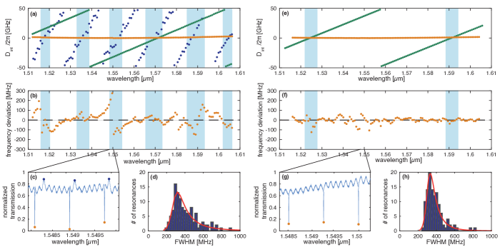
We compare the characterization of a standard resonator with constant waveguide width (Fig. 4(a-d)) to one including the mode filtering section with (tapered resonator, Fig. 4(e-h)). Mode family spectra are detected for both resonators (Fig. 4(a,e)). We identified two fundamental mode families and one higher order mode for the standard resonator, i.e. , and , while in the tapered resonator the higher order mode is suppressed. The transmission trace of the standard resonator, Fig. 4(c), shows the higher order mode that has Fano resonance shape Ding et al. (2014), together with the fundamental mode that has narrower resonance linewidths. The oscillating background is induced by the Fabry-Pérot interference between the two chip facet. The mode has the largest FSR according to simulations, which is measured to be . However, in the transmission trace of the tapered resonator, Fig. 4(g), resonances of mode are not observed. The FSR of the two fundamental modes remain approximately unchanged compared to the standard resonator. On the other hand, the parameter is reduced by introducing the mode filtering section, since the tapered waveguide section will contribute a small amount of normal GVD to the overall cavity dispersion. In the shown case, near 1550 nm is reduced from 1.0 MHz (standard waveguide) to 0.8 MHz (tapered resonator). Still, the tapered resonator is in the anomalous GVD regime that is necessary for the formation of dissipative Kerr soliton.
Since different modes have different FSRs, they show distinct slopes in the mode spectrum. Therefore, mode families cross with each other, implying resonances of two mode families are getting close at certain frequencies (crossing points), see Fig. 4(a,e). It is at such frequencies that avoided modal crossings appear. This can lead to strong local deviations from the parabolic curvature of the integrated dispersion, see Fig. 4(b) for the mode family of the standard resonator. In the tapered resonator, avoided modal crossings are much suppressed, see Fig. 4(f), by filtering out the higher order mode.
The resonance linewidth distribution was also investigated over the whole measurement wavelength range 1.51 – 1.61 , see Fig. 4(d,h). Both standard and tapered resonators have a similar distribution that can be fitted with a general Burr probability distribution function Burr (1942) in order to account for the mean value and the standard deviation of the resonance linewidth. A careful investigation of the resonance linewidth over different waveguide widths is shown in Fig. 3(b), with all resonators having the same coupling geometry and being almost critically coupled. This demonstrates that including a modal filtering section in SiN microresonators will not degrade the resonance Q factor (for values of ).
We next show the Kerr frequency comb generation based on temporal dissipative Kerr soliton formation in a SiN microresonator with filtering section. The laser detuning scheme introduced in Herr et al. (2013) was applied, in which the pump laser frequency is swept over a resonance of a fundamental mode and is stopped when the frequency comb generation is in the stable soliton state. One can also apply the “power kick” used in a previous work on soliton formation in SiN resonators Brasch et al. . Figure 5(b) shows the generated soliton comb in a 100 GHz microresonator with a taper waist . The corresponding integrated dispersion is shown in Fig. 5(a). The experiment employed 1 W of continuous wave pump light (at 1548 nm) in the waveguide. The soliton comb has a spectral span of 25 THz. The 3-dB bandwidth is 6.4 THz corresponding to the Fourier limited pulse duration of 48 fs. The frequency comb spectral envelope is fitted with a profile and reveals a slight asymmetry. The asymmetric spectral envelope is attributed to the third order dispersion () as well as the self-steepening effects of the microresonator, which induces asymmetry in the parabolic curvature in the dispersion. Moreover the soliton spectral envelope shows an offset of from the pump, which is attributed to the Raman induced soliton self-frequency shift as the intracavity soliton is estimated to have an intense peak power () Karpov et al. .
IV Conclusion
We have introduced a new resonator layout featuring a single mode filtering section for an integrated SiN platform. This design preserves the high Q and the anomalous GVD of the silicon nitride resonator, and effectively suppresses avoided modal crossings caused by the interaction of higher order transverse modes of the waveguide of the micro-ring resonator. This realizes an effectively single-mode micro-ring resonator with anomalous GVD. The new devices show significantly reduced local dispersion deviation due to avoided crossings. It is shown that the design enables reliable generation of temporal dissipative Kerr solitons. The approach is particularly useful for low free-spectral range resonators, or resonators with large number of transverse modes.
Funding Information
This publication was supported by Contract W31P4Q-14-C-0050 from the Defense Advanced Research Projects Agency (DARPA), Defense Sciences Office (DSO). This work was also supported by the Switzerland National Science Foundation (SNSF). VB acknowledges the support of the European Space Agency (ESA).
Acknowledgments
SiN microresonator samples were fabricated in the EPFL nanofabrication facility (CMi).
References
- Moss et al. (2013) D. Moss, R. Morandotti, A. Gaeta, and M. Lipson, Nature Photon. 7, 597 (2013).
- Levy et al. (2010) J. Levy, A. Gondarenko, M. Foster, A. Turner-Foster, A. Gaeta, and M. Lipson, Nature Photon. 4, 37 (2010).
- Zhao et al. (2015) H. Zhao, B. Kuyken, S. Clemmen, F. Leo, A. Subramanian, A. Dhakal, P. Helin, S. Severi, E. Brainis, G. Roelkens, and R. Baets, Opt. Lett. 40, 2177 (2015).
- Epping et al. (2015) J. Epping, T. Hellwig, M. Hoekman, R. Mateman, A. Leinse, R. Heideman, A. van Rees, P. van der Slot, C. Lee, C. Fallnich, and K. Boller, Opt. Express 23, 19596 (2015).
- Halir et al. (2012) R. Halir, Y. Okawachi, J. Levy, M. Foster, M. Lipson, and A. Gaeta, Opt. Lett. 37, 1685 (2012).
- Kippenberg et al. (2011) T. J. Kippenberg, R. Holzwarth, and A. Diddams, Science 332, 555 (2011), http://www.sciencemag.org/content/332/6029/555.full.pdf .
- Del’Haye et al. (2011) P. Del’Haye, T. Herr, E. Gavartin, M. Gorodetsky, R. Holzwarth, and T. J. Kippenberg, Phys. Rev. Lett. 107, 063901 (2011).
- Okawachi et al. (2011) Y. Okawachi, K. Saha, J. Levy, H. Wen, M. Lipson, and A. Gaeta, Opt. Lett. 36, 3398 (2011).
- Herr et al. (2012) T. Herr, K. Hartinger, J. Riemensberger, C. Wang, E. Gavartin, R. Holzwarth, M. Gorodetsky, and T. J. Kippenberg, Nature Photon. 6, 480 (2012).
- Pfeifle et al. (2014) J. Pfeifle, V. Brasch, M. Lauermann, Y. Yu, D. Wegner, T. Herr, K. Hartinger, P. Schindler, J. Li, D. Hillerkuss, R. Schmogrow, C. Weimann, R. Holzwarth, W. Freude, J. Leuthold, T. J. Kippenberg, and C. Koos, Nature Photon. 8, 375 (2014).
- Ferdous et al. (2011) F. Ferdous, H. Miao, D. Leaird, K. Srinivasan, J. Wang, L. Chen, L. T. Varghese, and A. Weiner, Nature Photon. 5, 770 (2011).
- Herr et al. (2013) T. Herr, V. Brasch, J. Jost, C. Wang, N. Kondratiev, M. Gorodetsky, and T. J. Kippenberg, Nature Photon. 8, 145 (2013).
- Liang et al. (2015) W. Liang, D. Eliyahu, V. Ilchenko, A. Savchenkov, A. Matsko, D. Seidel, and L. Maleki, Nat. Commun. 6, 7957 (2015).
- (14) V. Brasch, T. Herr, M. Geiselmann, G. Lihachev, M. Pfeiffer, M. Gorodetsky, and T. J. Kippenberg, “Photonic chip based optical frequency comb using soliton induced cherenkov radiation,” http://arxiv.org/abs/1410.8598/.
- (15) X. Yi, Q. Yang, K. Yang, M. Suh, and K. Vahala, “Generation of high-stability solitons at microwave rates on a silicon chip,” http://arxiv.org/abs/1508.00170/.
- Jost et al. (2015) J. Jost, T. Herr, C. Lecaplain, V. Brasch, M. Pfeiffer, and T. J. Kippenberg, Optica 2, 706 (2015).
- Pfeifle et al. (2015) J. Pfeifle, A. Kordts, P. Marin, M. Karpov, M. Pfeiffer, V. Brasch, R. Rosenberger, J. Kemal, S. Wolf, W. Freude, T. J. Kippenberg, and C. Koos, in CLEO: 2015 Postdeadline Paper Digest (Optical Society of America, 2015) p. JTh5C.8.
- Akhmediev and Karlsson (1995) N. Akhmediev and M. Karlsson, Phys. Rev. A 51, 2602 (1995).
- Coen et al. (2013) S. Coen, H. Randle, T. Sylvestre, and M. Erkintalo, Opt. Lett. 38, 37 (2013).
- Herr et al. (2014) T. Herr, V. Brasch, J. Jost, I. Mirgorodskiy, G. Lihachev, M. Gorodetsky, and T. J. Kippenberg, Phys. Rev. Lett. 113, 123901 (2014).
- Savchenkov et al. (2012) A. Savchenkov, A. Matsko, W. Liang, V. Ilchenko, D. Seidel, and L. Maleki, Opt. Express 20, 27290 (2012).
- Liu et al. (2014) Y. Liu, Y. Xuan, X. Xue, P. Wang, S. Chen, A. Metcalf, J. Wang, D. Leaird, M. Qi, and A. Weiner, Optica 1, 137 (2014).
- Miller et al. (2015) S. A. Miller, Y. Okawachi, S. Ramelow, K. Luke, A. Dutt, A. Farsi, A. Gaeta, and M. Lipson, Opt. Express 23, 21527 (2015).
- Chembo and Yu (2010) Y. Chembo and N. Yu, Phys, Rev. A 82, 033801 (2010).
- Oxborrow (2007) M. Oxborrow, IEEE T. Microw. Theory 55, 1209 (2007).
- Carmon et al. (2008) T. Carmon, H. Schwefel, L. Yang, M. Oxborrow, D. Stone, and K. Vahala, Phys. Rev. Lett. 100, 103905 (2008).
- Pfeiffer et al. (pted) M. Pfeiffer, A. Kordts, V. Brasch, C. Lecaplain, J. Jost, M. Geiselmann, and T. J. Kippenberg, Optica, doc. ID 247876 (2015, accepted).
- Riemensberger et al. (2012) J. Riemensberger, K. Hartinger, T. Herr, V. Brasch, R. Holzwarth, and T. J. Kippenberg, Opt. Express 20, 27661 (2012).
- Ding et al. (2014) D. Ding, M. Dood, J. Bauters, M. Heck, J. Bowers, and D. Bouwmeester, Opt. Express 22, 6778 (2014).
- Burr (1942) I. Burr, Ann. Math. Statist. 13, 215 (1942).
- (31) M. Karpov, H. Guo, A. Kordts, V. Brasch, M. Pfeiffer, M. Zervas, M. Geiselmann, and T. J. Kippenberg, “Raman induced soliton self-frequency shift in microresonator Kerr frequency combs,” http://arxiv.org/abs/1506.08767.