Wigner crystal in a two-dimensional electron system in the vicinity of filling factor 1/5: Acoustic studies
Abstract
By simultaneous measurements of the attenuation and velocity of
surface acoustic waves propagating in proximity to a high-quality
GaAs quantum well we study the complex AC conductance of the
two-dimensional electron system. Focusing on the vicinity of the
filling factor we confirm that the insulating states
formed closely to this value of are pinned Wigner crystals.
pacs:
73.23.- b, 73.50.Rb, 73.43.QtI Introduction
The nature of the ground state of a two-dimensional electron system (2DES) in a large perpendicular magnetic field has attracted a lot of attention. At small filling factors, where is the 2DES density, is the reduced Planck constant, and is the electronic charge, the ground state in the absence of disorder is expected to be the Wigner crystal (WC) Lozovik1975 ; Yoshioka1979 ; Fisher1982 ; Yoshioka1983 ; Lam1985 . Another known ground states are the fractional quantum Hall effect (FQHE) states Tsui1982 ; Laughlin1983 . Both states are induced by the electron-electron interaction. It turns out that the Laughlin FQHE liquid states at (where and are integers) are particularly robust and have ground state energies which are lower than the WC state energy, at least for Sajoto1993 . Theoretical calculations predict that, in an ideal 2DES system, the WC should be the ground state for smaller than about 1/6. However, the WC state may win as the filling deviates slightly from 1/5. It is possible therefore to have a WC, which is reentrant around a FQHE liquid state, see Fig. 9 in [Shayegan2005, ]. This would rationalize the general current belief that the insulating phase (IP) observed around the FQHE in very high quality GaAs/AlGaAs 2DESs is the signature of a WC state pinned by a disorder potential. The magnetic-field-induced WC problem in 2DESs has been studied extensively since the late 1980s Shayegan1997 ; Pan2002 .
In 2D systems along with DC measurements of the components of the magneto-resistance tensor many research groups study AC conductivity , which is a probeless way for investigation of the AC conductance. The rf electric field can be excited using the coplanar-wave-guide (CPW) technique Wen1969 . This method was successfully employed for studies of the FQHE in [Engel1993, ] and other works.
Another probeless method is using traveling electric wave created by a surface acoustic wave (SAW). In connection with the integer QHE structures it was implemented in [Wixforth1986, ; Drichko2000, ] and subsequent works; the FQHE was studied using this method in [Paalanen1992, ] and [Paalanen1992a, ]. AC methods provide the information additional to the DC results. In particular, specific resonances in the AC response allow one to identify the nature of the insulating states observed at specific values of the filling factor.
The microwave spectroscopy (MWS) based on the CPW technique and the acoustic spectroscopy (AS) based on studies of the attenuation and velocity v of a SAW provide complementary information. MWS allows studying the high-frequency response while the frequency of the excited SAW is limited. However, the AS allows calculating both (real and imaginary) components of the complex AC conductance from simultaneous measurement of the SAW attenuation and variation of its velocity v/v0 versus perpendicular magnetic field . This is an obvious advantage of the AS, which we employ in the present study.
Usually the frequency domains used in MWS and AS do not overlap. However, recently is was shown that the frequency windows might overlap providing a possibility for quantitative studies of AC conductance in a broad frequency domain Drichko2014 .
In the present work, we address the insulating phases observed in the high-quality GaAs quantum wells in the vicinity of . These phases are ascribed to formation of a disorder-pinned Wigner crystal (WC) Paalanen1992a . Our aim is to extend studies of this region by simultaneous analysis of the real and imaginary parts of the complex AC conductance. Comparing the results with the theory Fogler2000 we show that the behaviors of and are indeed characteristic for a pinned WC.
II Experiment
II.1 Methodology
We use the so-called hybrid acoustic method discussed in detail in Ref. Drichko2000, , see Fig. 1 (left). The sample is pressed by springs to a surface of a LiNbO3 piezoelectric crystal where two inter-digital transducers (IDTs) are formed. One of the IDTs is excited by AC pulses. As a result, a surface acoustic wave (SAW) is generated, which propagates along the surface of the piezocrystal. The piezoelectric field penetrates into the sample interacting with the charge carriers. This interaction causes SAW attenuation and deviation of its velocity. Measurement of both SAW attenuation and velocity versus perpendicular magnetic field allows one finding complex AC conductance, , as a function of magnetic field.
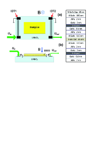
II.2 Samples
We study multi-layered -GaAlAs/GaAs/GaAlAs structures with a wide (65 nm) GaAs quantum well (QW), see Fig. 1 (right). The QW is -doped from both sides and is located at the depth of 845 nm from the surface. The electron density is cm-2 and the mobility is cm2/Vs. One can expect that at the given electron density only lowest band of transverse quantization is occupied Manoharan1996 .
II.3 Experimental results
Both attenuation of SAW and variation of its velocity were measured in several samples versus perpendicular magnetic field of up to 18 T in the frequency domain MHz at temperatures mK. The samples were cut form the same chip. The electron density in the samples is diffed by %.
Shown in Fig, 2 are magnetic field dependences of the attenuation and relative deviation of the SAW velocity v/v at MHz, and mK. The curves for different frequencies and temperatures are similar. Magnetic field has first increased form 0 up to 18 T (black curves) and then decreased (red curves) down to -0.3 T. The curves overlap confirming that there is no hysteresis. We have checked that the measurements correspond to the linear response regime.
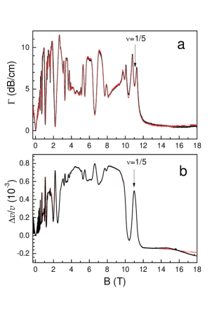
The complex AC conductance was determined using Eqs. (1)-(7) from Drichko2000 where we substituted , and for the dielectric constants of LiNbO3, of the vacuum and of the sample, respectively. The finite vacuum clearance cm between the sample surface and the LiNbO3 surface was determined from saturation of the SAW velocity in a strong magnetic field at mK; nm is the finite distance between the sample surface and the 2DES layer. The SAW velocity in zero magnetic field is cm/s.
Dependence of on the inverse filling factor is shown in Fig. 3. This picture evidences a rich oscillation pattern including features of both integer and fractional quantum Hall effect.

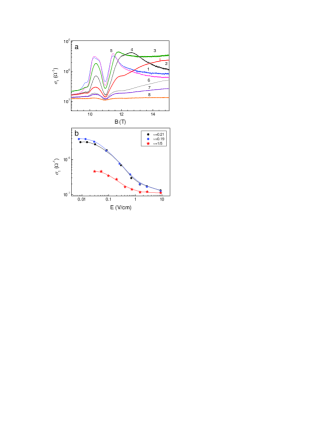
Our primary aim is to study in a vicinity of . The magnetic field dependence of for different frequencies is shown in Fig. 4 (a). Frequency dependences of and for and, mK are shown in Fig. 4 (b).
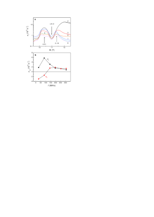
As shown in Fig. 4 (b), has a maximum at MHz, while the imaginary part, , changes its sign. Similar behaviors were observed for . A special behavior of is observed at . At this value of the frequency dependence of is smooth. This is compatible with the conclusion that at the FQHE state wins and no Wigner crystal is formed. The observed mode is close to the so-called B-mode found in [Chen2004, ] for a similar sample.
II.4 Dependences on intensity and temperature
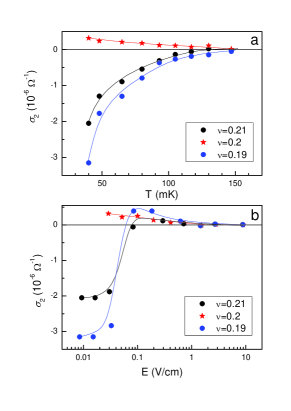
Magnetic field dependences of at different temperatures and its temperature dependences at different filling factors are shown in Fig. 5.
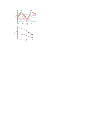
As temperature increases the maxima of (corresponding to and 0.21) decrease much more rapidly than the conductance at . Following [Paalanen1992a, ] we interpret this behavior as melting of the Wigner crystal.
Note that temperature dependences of are qualitatively similar for , 0.20, and 0.21, contrary to the temperature dependences of DC conductance. Indeed, according to [Jiang1990, ] the temperature dependences of are qualitatively different for and : compare Fig. 2 and Fig. 3 of that paper. At , while at , .
The dependences of on magnetic field for different SAW intensities are shown in Fig. 6 (a). Shown in Fig. 6 (b) are the dependences of versus the SAW electric field amplitude for different filling factros: , 0.20, and 0.21. These dependences were measured at frequency MHz and temperature mK.
Since the dependences of on temperature and SAW intensity are qualitatively similar, one concludes that the main mechanism behind nonlinear response to a SAW is heating of 2DES due to the energy SAW dissipated in course of SAW attenuation.
Dependences of on and at MHz are shown in Fig. 7. Again, we observe that the temperature dependences of are similar for and , but is qualitatively different from the temperature dependence for . The dependences of on the amplitude of the SAW electric field are similar to the temperature dependences, thus, supporting the idea that the main mechanism behind nonlinear behaviors is the Joule heating.
III Discussion and conclusions
The behavior of shown in Fig. 5 (b) is typical for a pinned mode of a Wigner crystal Fertig1999 ; Yi2000 ; Fogler2000 ; Chitra2001 ; Fogler2004 , see Refs.Shayegan1997, ; Shayegan2005, for a review. It manifests itself in observed resonances in Ye2002 , which has been taken as a signature of a solid and interpreted as due to the pinning mode (the disorder gapped lower branch of the magnetophonon) Fukuyama1978 ; Normand1992 ; Fertig1999 ; Fogler2000 ; Chitra2001 of WC crystalline domains oscillating collectively within the disorder potential. The WC states compete with the fractional quantum Hall effect (FQHE) states; based on several experiments and calculations it is concluded that at the FQHE dominates while at slightly less or slightly higher the WC state wins, see, e.g., Fig. 9 from Shayegan2005 .
The dynamic response of a weakly pinned Wigner crystal at not too small frequencies is dominated by the collective excitations Fertig1999 ; Fogler2000 ; Fogler2004 where an inhomogeneously broadened absorption line (the so-called pinning mode) appears Fukuyama1977 ; Fukuyama1978 . It corresponds to collective vibrations of correlated segments of the Wigner crystal around their equilibrium positions formed by the random pinning potential. The mode is centered at some disorder- and magnetic-field-dependent frequency, (so-called pinning frequency); its width being determined by a complicated interplay between different collective excitations in the Wigner crystal. There are modes of two types: transverse (magnetophonons) and longitudinal (magnetoplasmons). The latters include fluctuations in electron density. An important point is that the pinning modifies both modes, and the final result depends on the strength and the correlation length, , of the random potential. Depending in the strength and correlation length of the random potential, the frequency, may either increase, or decrease with the magnetic field. The ratio , where is the cyclotron frequency, can be arbitrary. Depending on the interplay between the ratio and the ratio between the shear () and bulk () elastic moduli one can specify two regimes where the behaviors of are different:
| (1) |
Here is the pinning frequency at . As a result, the variety of different behaviors is very rich. Assuming one can cast the expression for from Ref. Fogler2000 into the form
| (2) |
where the function is different for regimes (a) and (b).
Let us consider the regime (b) since only this regime seems to be compatible with our experimental results. Then
| (3) |
Here , while is some critical exponent. According to Ref. Fogler2000, , .
Assuming the regime (b1) we can cast Eq. (2) in the form where
| (4) |
Graphs of for several are shown in Fig. 8. This function is normalized in order to have its maxima -independent.
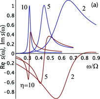
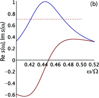
Unfortunately, the experimental data shown in Fig. 4 (b) do not provide an accurate structure of the maximum, and therefore do not allow fitting the model with high accuracy. Assuming that gives approximately correct shape of the curves in Fig. 4 (b) and taking into account that the maximum of occurring at MHz corresponds to we conclude that MHz. The quantity plays the role of pinning frequency in the magnetic field Fogler2000 .
The frequency can then be determined as . Substituting , MHz, MHz we obtain MHz. Therefore, the regime (b) of Eq. (1) is the case, as we expected. Estimating the WC correlation length as where cm/s is the velocity of the WC transverse mode for our electron density we obtain cm that is much larger both than the distance between the electrons and the magnetic length . These inequalities justify using the theory Fogler2000 for estimates.
To summarize, from simultaneous measurements of attenuation and velocity SAW propagating in proximity of 2DES in perpendicular magnetic fields we have calculated both real and imaginary parts of the complex AC conductance, . Our analysis shows that at low temperatures and at the filling factor of 0.20 the electron system resides in the FQHE state. However, close to this value, at and 0.21, the electron state can be interpreted as a so-called weakly pinned Wigner crystal. When the temperature (or the SAW intensity) increases the behavior of the complex conductance can be understood as manifestation of WC melting. Our conclusions support the interpretation based on DC and microwave measurements, as well as on previous acoustic measurements of only real part of the AC conductance.
Acknowledgments
I.L.D. is grateful for support from Russian Foundation for Basic Research via grant 14-02-00232. The authors would like to thank E. Palm, T. Murphy, J.-H. Park, and G. Jones for technical assistance. NHMFL is supported by NSF Cooperative Agreement No. DMR-1157490 and the State of Florida. The work at Princeton was partially funded by the Gordon and Betty Moore Foundation through Grant GBMF2719, and by the National Science Foundation MRSEC-DMR-0819860 at the Princeton Center for Complex Materials.
References
References
- (1) Y. E. Lozovik and V. I. Yudson, Pis’ma v Zh. Eksp. Teor. Fiz. 22, 26 (1975), [JETP Lett. 22, 11 (1975)].
- (2) D. Yoshioka and H. Fukuyama, J. Phys. Soc. Jpn. 47, 394 (1979).
- (3) D. S. Fisher, Phys. Rev. B 26, 5009 (1982).
- (4) D. Yoshioka and P. A. Lee, Phys. Rev. B 27, 4986 (1983).
- (5) P. K. Lam and S. M. Girvin, Phys. Rev. B 30, 473 (1984).
- (6) D. C. Tsui, H. L. Stormer, and A. C. Gossard, Phys. Rev. Lett. 48, 1559 (1982).
- (7) R. B. Laughlin, Phys. Rev. Lett. 50, 1395 (1983).
- (8) T. Sajoto, Y. P. Li, L. W. Engel, D. C. Tsui, and M. Shayegan, Phys. Rev. Lett. 70, 2321 (1993).
- (9) M. Shayegan, Flatland Electrons in High Magnetic Fields (World Scientific Co, Singapore, 2006), vol. 3 of High Magnetic Fields: Science and Technology, pp. 31-60, ArXive: cond-mat/0505520v1.
- (10) M. Shayegan, Perspectives in Quantum Hall Effects (Wiley, New York, 1997), chap. 9.
- (11) W. Pan, H. L. Stormer, D. C. Tsui, L. N. Pfeiffer, K. W. Baldwin, and K. W. West, Phys. Rev. Lett. 88, 176802 (2002).
- (12) C. P. Wen, IEEE Trans. Microwave Theory Tech. 17, 1087 (1969).
- (13) L. W. Engel, D. Shahar, C. Kurdak, and D. C. Tsui, Phys. Rev. Lett. 71, 2638 (1993).
- (14) A. Wixforth, J. P. Kotthaus, and G. Weimann, Phys. Rev. Lett. 56, 2104 (1986).
- (15) I. L. Drichko, A. M. Diakonov, I. Y. Smirnov, Y. M. Galperin, and A. I. Toropov, Phys. Rev. B 62, 7470 (2000).
- (16) M. A. Paalanen, R. L. Willett, P. B. Littlewood, R. R. Ruel, K. W. West, L. N. Pfeiffer, and D. J. Bishop, Phys. Rev. B 45, 11342 (1992).
- (17) M. A. Paalanen, R. L. Willett, R. R. Ruel, P. B. Littlewood, K. W. West, and L. N. Pfeiffer, Phys. Rev. B 45, 13784(R) (1992).
- (18) I. L. Drichko, A. M. Diakonov, V. A. Malysh, I. Y. Smirnov, Y. M. Galperin, N. D. Ilyinskaya, A. A. Usikova, M. Kummer, H. von Känel, J. Appl. Phys. 116, 154309 (2014).
- (19) M. M. Fogler and D. A. Huse, Phys. Rev. B 62, 7553 (2000).
- (20) H. C. Manoharan, Y. W. Suen, M. B. Santos, and M. Shayegan, Phys. Rev. Lett. 77, 1813 (1996).
- (21) Y. P. Chen, R. M. Lewis, L. W. Engel, D. C. Tsui, P. D. Ye, Z. H. Wang, L. N. Pfeiffer, K. W. West, Phys. Rev. Lett. 93, 206805 (2004).
- (22) H. W. Jiang, R. L. Willett, H. L. Stormer, D. C. Tsui, L. N. Pfeiffer, K. W. West, Phys. Rev. Lett. 65, 633 (1990).
- (23) I. L. Drichko, V. A. Malysh, I. Y. Smirnov, A. V. Suslov, O. A. Mironov, M. Kummer, H. von Känel, J. Appl. Phys. 114, 074302 (2013).
- (24) H. A. Fertig, Phys. Rev. B 59, 2120 (1999).
- (25) H. Yi, H. A. Fertig, Phys. Rev. B 61, 5311 (2000).
- (26) R. Chitra, T. Giamarchi and P. Le Doussal, Phys. Rev. B 65, 035312 (2001).
- (27) M. M. Fogler, Physica E 22, 98 (2004).
- (28) P. D. Ye, L. W. Engel, D. C. Tsui, R. M. Lewis, L. N. Pfeiffer, K. West, Phys. Rev. Lett. 89, 176802 (2002).
- (29) H. Fukuyama, P. A. Lee, Phys. Rev. B 18, 6245 (1978).
- (30) B. G. A. Normand, P. B. Littlewood, A. J. Millis, Phys. Rev. B 46, 3920 (1992).
- (31) H. Fukuyama, P. A. Lee, Phys. Rev. B 17, 535 (1978).