Cavity magnomechanics
A dielectric body couples with electromagnetic fields through radiation pressure and electrostrictive forces, which mediate phonon-photon coupling in cavity optomechanics Aspelmeyer2014 . In a magnetic medium, according to Korteweg-Helmholtz formula Zahn2006 , magnetostrictive forces should arise and lead to phonon-magnon interaction. Here we report such a coupled phonon-magnon system based on ferrimagnetic spheres, which we term as cavity magnomechanics, by analogy to cavity optomechanics. Coherent phonon-magnon interactions, including electromagnetically induced transparency and absorption, are demonstrated. Excitingly, due to strong hybridization of magnon and microwave photon modes and their high tunability, our platform exhibits new features including parametric amplification of magnons and phonons, triply resonant photon-magnon-phonon coupling and phonon lasing. Our work demonstrates the fundamental principle of cavity magnomechanics and its application as a new information transduction platform based on coherent coupling between photons, phonons and magnons.
Mechanical oscillators have been recently widely studied as a transducer mediating the coherent signal conversion between different systems Aspelmeyer2014 . Particularly, radiation force Li2008 ; Park2009 ; Weis2010 ; Safavi-Naeini2011 ; Hill2012 , electrostatic force Teufel2011 ; Andrews2014_NPhys ; Bagci2014 and piezoelectric force Bochmann2013 ; Fan2015 have been utilized for coupling phonon with optical or microwave photons. Such interaction mechanisms lead to the fast development of a variety of cavity electro- and opto-mechanical systems Aspelmeyer2014 , but they all intrinsically lack good tunability. The magnetostrictive force Zahn2006 provides an alternative mechanism to allow a different information carrier – magnon – to couple with phonon. Magnon is a collective excitation of magnetization, whose frequency can be tuned at will by adjusting bias magnetic field Serga2010 ; Lenk2011 ; Chumak2015 . The magnetostrictive interaction has been long overlooked for information processing as it is negligibly weak in commonly used dielectric or metallic materials. However, in magnetic materials such as yttrium iron garnet (YIG, Y3Fe5O12), the magnetostrictive force becomes dominant, which provides a great opportunity to establish an highly tunable hybrid system for coherent information processing. Thanks to the excellent material property of YIG, the magnomechanical system can be further integrated with opto- or electro-mechanical elements, providing an excellent platform for quantum state transfer among different physical systems.
Here, we demonstrate an intriguing cavity magnomechanical system in which magnon couples with phonon through magnetostrictive interaction, resulting in hallmark coherent phenomena such as magnomechanically induced transparency/absorption (MMIT/MMIA) and magnomechanical parametric amplification (MMPA). During such processes, magnons are in the hybridized state with cavity microwave photons as they are strongly coupled to each other Tabuchi2014_PRL ; Zhang2014_PRL ; Goryachev2014 ; Bai2015 ; Kurizki2015 . Therefore coherent signal conversions among these three different information carriers are realized in a single device. The magnetic field dependence of magnon provides our system with unprecedented tunability compared with opto- or electro-mechanical systems. Moreover, the great flexibility of this system allows us to achieve triple-resonance among magnon, phonon and photon, which drastically enhances the magnomechanical interaction. The principles demonstrated in our room temperature experiments can be readily applied to the quantum regime at millikelvin temperature, opening up great opportunities in various applications, such as tunable microwave filter and amplifier Bergeal2010 , long-lifetime quantum memories Fiore2011_PRL , microwave-to-optics conversion Andrews2014_NPhys .
Magnetostrictive interaction
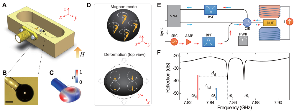
The device used in our experiments is
schematically shown in Fig. 1A. The
key component is a highly polished single crystal
YIG sphere glued to the end of a silica fiber for
supporting purpose (Fig. 1B). With
an external magnetic field biased along
direction, a uniform magnon mode resonates in the
YIG sphere at frequency
, where is
the gyromagnetic ratio. The YIG sphere is also an
excellent mechanical resonator
(Fig. 1C) thanks to its superior
material and geometrical properties. The varying
magnetization induced by the magnon excitation
inside the YIG sphere causes deformation of its
spherical geometry (and vise versa), introducing
the coupling between magnon and phonon modes
(Fig. 1D). Considering the large
frequency mismatch between the magnon and the
phonon modes (gigahertz v.s. megahertz) with our
experiment parameters, a strong parametric drive
is used to compensate their frequency difference.
In this case, the system is described by an
radiation pressure-like, dispersive interaction
Hamiltonian ,
where is the reduced Planck’s constant,
() is the boson operator of
the phonon (magnon) mode, and
is the single magnon-phonon coupling strength.
Spheroidal phonon modes
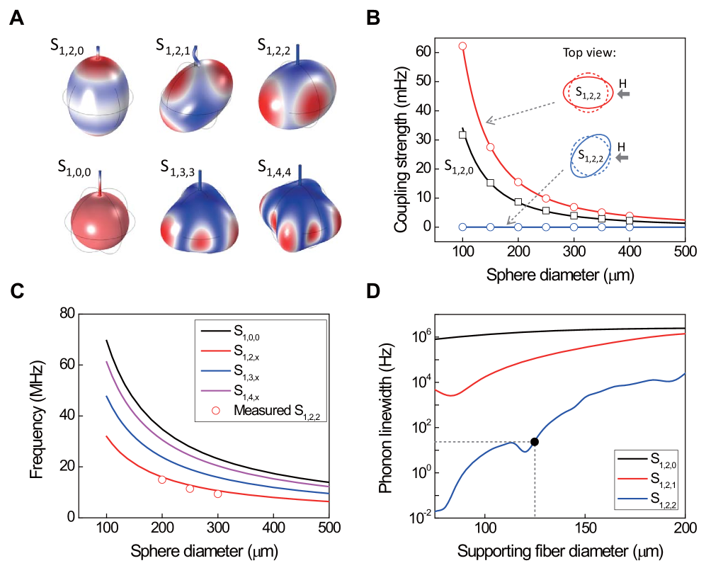
The magnetostrictive coupling strength is
determined by the mode overlap between the
uniform magnon mode and the phonon modes. In a
YIG sphere, there exist various phonon modes,
each with a different displacement profile and
consequently a different coupling strength with
the magnon mode. Figure 2A plots
the typical profiles of the lowest order
spheroidal phonon modes S ( and
are the angular and azimuthal mode
numbers, respectively), among which the
S1,2,2 mode shows the highest coupling
strength when the bias field is along the
direction of maximum displacement
(Fig. 2B). Therefore in our
experiments we focus only on the S1,2,2
mode. Although a YIG sphere with a smaller
diameter is favorable for achieving larger
coupling strengths (Fig. 2B), it
also results in a higher frequency for the phonon
mode (Fig. 2C), which in turn leads
to lower responsivity to the parametric drive, so
a trade-off has to be made when choosing the
sphere size. In our experiments, a
250-m-diameter YIG sphere is used,
corresponding to a phonon frequency
MHz and a
coupling strength
mHz. With an external drive of 0 dBm, the linear
magnon-phonon coupling can be enhanced to around
kHz, which is two orders of magnitude larger
than the phonon dissipation rate
.
Magnetostriction mediates the coupling between magnons and photons. However, in order to achieve coherent magnon-phonon coupling, it is further required that phonon mode should have relatively long lifetime. Single crystal YIG has a garnet structure that is known to exhibit very low mechanical damping and therefore supports a material-limited phonon lifetime over a millisecond LeCraw1961 . The supporting fiber that is glued to the YIG sphere reduces the phonon lifetime (Fig. 2D). In our experiments, the measured linewidth of S1,2,2 phonon mode with a 125-m-diameter supporting fiber is Hz, which is sufficiently small for observing coherent magnon-phonon coupling phenomena.
Coherent magnomechanical interaction
Figure 1E plots the schematics of
our measurement setup at room temperature ambient
condition. The YIG sphere is placed inside a
three-dimensional microwave cavity
(Fig. 1A). A weak probe signal is
sent into the cavity through a coaxial probe, and
by sweeping its frequency
and measuring the reflection, we can infer the
interaction among photon, magnon and phonon
inside the cavity. The YIG sphere is positioned
at the maximum microwave magnetic field of the
cavity TE011 mode, which resonates at
GHz. By
controlling the bias magnetic field, we tune the
magnon close to resonance with the cavity photon
mode. This leads to the hybridization between
magnon and photon Zhang2014_PRL ; Tabuchi2014_PRL ; Goryachev2014 ; Bai2015 , which
shows up in the reflection spectrum as a pair of
split normal modes (Fig. 1F).
Because each of the two hybrid modes contains
magnon components, it coherently couples with the
phonon modes when the cavity is parametrically
driven by a strong microwave signal at
.
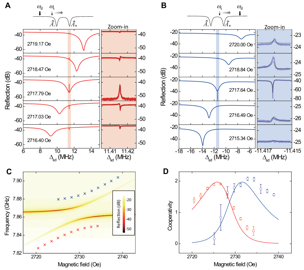
We first study the coherent magnomechanical coupling for each individual hybrid mode by applying an off-resonance microwave drive. In this case, the cavity magnomechanical system can be described by
| (1) |
where the two hybrid modes interact with the phonon mode independently. Here, and are quantized boson operators for hybridized excitations constituted by magnon and microwave photon (), with varies with photon-magnon coupling strength and photon-magnon detuning . In our system, both the magnon and the cavity photon modes have a relatively narrow linewidth ( MHz and MHz). As a result, the hybrid mode linewidth is well below the phonon frequency, leading our system deep inside the resolved sideband regime, by analogy with optomechanical systems Aspelmeyer2014 . In this case, the nonlinear interaction can be converted either into the linear beam splitter model or the parametric oscillator model with the presence of an external drive, where is the enhanced coupling strength. Here, is the steady state amplitude of the hybrid mode, corresponding to the effective pumping of the microwave drive on magnon due to the magnon-photon hybridization.
Figures 3A and B plot the measured reflection spectra for a series of bias magnetic fields with a microwave drive at a fixed frequency . To avoid the influence of the other hybrid mode, the driving signal is red (blue) detuned for the lower (upper) hybrid mode, as illustrated by the top insets. For the red-detuned drive, the power is held constant at 26 dBm. In the spectra, the broad Lorentzian-shaped resonance dip corresponds to the hybrid mode , while the very sharp modification of the spectra at the two-photon detuning is evidence of coherent magnomechanical interaction. The zoomed-in spectra in Fig. 3A show that these phonon-induced resonances have a Fano-like shape that varies with bias magnetic field. When the drive-resonance detuning , the Fano-like resonance changes into a symmetric Lorentzian-shaped transparency peak (MMIT). In contrast, the Fano-like resonances in the spectra for the blue-detuned drive (with a constant power of 22 dBm) show an opposite symmetry (Fig. 3B). When the drive is blue detuned to , such a resonance becomes a Lorentzian-shaped absorption dip (MMIA).
One distinct advantage of magnon is that its frequency is determined by the external bias magnetic field and therefore can be conveniently tuned in a broad range. By varying , the percentage of magnon component in the hybrid mode changes. Therefore, the hybrid mode experiences different effective dissipation rate, external coupling rate, as well as effective coupling strength with the phonon mode. As a result, the coherent magnomechanical interaction is magnetically controllable, which can be quantified by the dependence of the cooperativity on the bias magnetic field. The measured - relation is plotted in Fig. 3D. For each measurement under a specific bias condition, the drive frequency is detuned from the hybrid mode by , as indicated by the crosses in Fig. 3C, while the driving power is fixed constant at . We can see there exists an optimal condition for a maximum , as a the result of the competition between the magnon and photon components in the hybrid mode: more magnon component yields stronger magnetostrictive coupling, while more photon component leads to a higher driving efficiency. From these measurement results we can extract the magnon-phonon coupling strength mHz, in accordance with our theoretical prediction (Fig. 2B).
Triply resonant cavity magnomechanics
The great flexibility of our system leads to
tremendous advantages. For instance, it allows us
to work in the interesting triple-resonance
condition, where both maximum hybridized modes
simultaneously couple with the phonon mode, as
described by
| (2) |
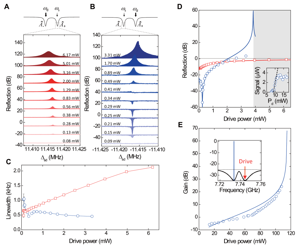
By adjusting the direction of bias field or the position of the YIG sphere inside the cavity, we can tune the hybrid mode splitting to match the phonon frequency . In this case, both the drive and probe photons can be applied on-resonance with the hybrid modes (top inset of Figs. 4A and B), resulting in a drastically enhanced magnomechanical coupling. For the red-detuned drive, the transparency windows at various driving powers are plotted in Fig. 4A. In addition to the red shift of the center frequency, the linewidth of the transparency windows exhibits a clear linear dependence on the driving power (Fig. 4C, red squares). With a driving power of only 8.0 dBm, the linewidth increases from its intrinsic value to , corresponding to a cooperativity . As a comparison, a driving power of is used to achieve the same cooperativity when the drive is applied off-resonance, indicating the drastic enhancement of the magnomechanical interaction induced by the triple-resonance condition. The reflection signal for the blue detuning situation is plotted in Fig. 4B at various driving powers. As the driving power increases, the center frequency of the small phonon-induced resonance inside the hybrid mode is blue shifted, and its linewidth linearly decreases (Fig. 4C, blue circles).
A direct comparison of Figs. 4A and B reveals distinctly different spectral lineshapes of the phonon-induced resonances. The same as in the case of off-resonance drive, we observed MMIT for the red-detuned drive in the triply resonant system, with the peak height and linewidth of the transparency window increasing with the driving power. While for the blue-detuned drive, we observed the transition from MMIA to MMIT, and then to MMPA and eventually self-sustained oscillation as we increase the driving power. These observations lead to a unified explanation about the modified spectral lineshape (which is not limited to the triple resonance situation): the coupling with phonon introduces additional dissipation and phase shift to the hybridized modes and therefore changes their lineshapes. With the presence of a parametric drive, the effective dissipation rate of the hybrid mode is modified from to , which increases for the red-detuned drive while decreases for blue-detuned drive. Given a fixed external coupling rate , the on-resonance reflectivity of the cavity is
| (3) |
Therefore, depending on the external coupling condition and the driving power, the reflection spectra lineshape varies among MMIT, MMIA or MMPA.
The measured on-resonance reflectivity for an under-coupled hybrid mode agrees well with our theoretical model (Fig. 4D). For the red-detuned drive, the increasing linewidth with elevated driving power causes the mode further under-coupled and therefore the on-resonance reflectivity increases. On the contrary, for the blue-detuned situation, the decreasing linewidth first leads to critical coupling and then over coupling condition, yielding a dip in the reflectivity followed by a rapid increase which diverges as at a driving power of 6.2 dBm. The deviation of the measured reflectivity from the theoretical prediction can be attributed to thermal instability or gain-bandwidth-product limitation, which also limit the highest measurable parametric gain to 3 dB. When the hybrid mode is tuned to over coupled, the increase of the parametric gain with the driving power is more gradual, and therefore a much higher parametric gain up to dB is achieved before reaching instability (Fig. 4E). The observed MMPA is similar to the electromechanical parametric amplifiers Massel2011_Nature but with unprecedented tunability. Further increasing the driving power leads the system into the instable regime where the phonon mode experiences self-sustained oscillation. The threshold behavior of the measured emission power from the Stokes sideband, as shown by the inset of Fig. 4D, indicates the onset of the phonon lasing Spencer1958 .
Conclusion
The demonstration of the coherent magnon-phonon
interaction, including the MMIT (MMIA) and MMPA,
provides a versatile platform for the coherent
information processing. Besides, as YIG also
possesses great optical properties such as low
optical loss and optomagnetic nonreciprocity, our
study shows great potential for integrating
different systems, including microwave, optical,
mechanical and magnonic systems, in a single
device and realizing information inter-conversion
among these different information carriers.
Distinguished from opto- or electro-mechanical
systems, our cavity magnomechanical system shows
high level of tunability which allows the
resonance be externally controlled in a wide
frequency range. Moreover, such a complex system
is compatible with superconducting quantum
circuits Tabuchi2015 . All of these are not
only crucial for realizing long desired functions
such as microwave-to-optical conversion
Andrews2014_NPhys ; Bagci2014 ; Bochmann2013 ; Vitali2012 ; Clerk2012 , but also provide a
flexible platform that intrigues the fundamental
study of exotic magnetic excitations.
References
- (1) M. Aspelmeyer, T. J. Kippenberg, F. Marquardt, Cavity optomechanics. Rev. Mod. Phys. 86, 1391–1452 (2014).
- (2) M. Zahn. Derivation of the Korteweg-Helmholtz electric and magnetic force densities including electrostriction and magnetostriction from the quasistatic Poynting’s theorems. In 2006 IEEE Conf. Electr. Insul. Dielectr. Phenom., 186–189. IEEE (2006).
- (3) M. Li et al., Harnessing optical forces in integrated photonic circuits. Nature 456, 480–484 (2008).
- (4) Y.-S. Park, H. Wang, Resolved-sideband and cryogenic cooling of an optomechanical resonator. Nature Phys. 5, 489–493 (2009).
- (5) S. Weis et al., Optomechanically induced transparency. Science 330, 1520–1523 (2010).
- (6) A. H. Safavi-Naeini et al., Electromagnetically induced transparency and slow light with optomechanics. Nature 472, 69–73 (2011).
- (7) J. T. Hill, A. H. Safavi-Naeini, J. Chan, O. Painter, Coherent optical wavelength conversion via cavity optomechanics. Nat. Commun. 3, 1196 (2012).
- (8) J. D. Teufel et al., Circuit cavity electromechanics in the strong-coupling regime. Nature 471, 204–208 (2011).
- (9) R. W. Andrews et al., Bidirectional and efficient conversion between microwave and optical light. Nature Phys. 10, 321–326 (2014).
- (10) T. Bagci et al., Optical detection of radio waves through a nanomechanical transducer. Nature 507, 81–85 (2014).
- (11) J. Bochmann, A. Vainsencher, D. D. Awschalom, A. N. Cleland, Nanomechanical coupling between microwave and optical photons. Nature Phys. 9, 712–716 (2013).
- (12) L. Fan, K. Y. Fong, M. Poot, H. X. Tang, Cascaded optical transparency in multimode-cavity optomechanical systems. Nat. Commun. 6, 5850 (2015).
- (13) A. A. Serga, A. V. Chumak, B. Hillebrands, YIG magnonics. J. Phys. D. Appl. Phys. 43, 264002 (2010).
- (14) B. Lenk, H. Ulrichs, F. Garbs, M. Münzenberg, The building blocks of magnonics. Phys. Rep. 507, 107–136 (2011).
- (15) A. V. Chumak, V. I. Vasyuchka, A. A. Serga, B. Hillebrands, Magnon spintronics. Nature Phys. 11, 453–461 (2015).
- (16) Y. Tabuchi et al., Hybridizing ferromagnetic magnons and microwave photons in the quantum limit. Phys. Rev. Lett. 113, 083603 (2014).
- (17) X. Zhang, C.-L. Zou, L. Jiang, H. X. Tang, Strongly coupled magnons and cavity microwave photons. Phys. Rev. Lett. 113, 156401 (2014).
- (18) M. Goryachev et al., High-cooperativity cavity QED with magnons at microwave frequencies. Phys. Rev. Appl. 2, 054002 (2014).
- (19) L. Bai, M. Harder, Y. P. Chen, X. Fan, J. Q. Xiao, C.-M. Hu, Spin pumping in electrodynamically coupled magnon-photon systems. Phys. Rev. Lett. 114, 227201 (2015).
- (20) G. Kurizki et al., Quantum technologies with hybrid systems. Proc. Natl. Acad. Sci. 112, 3866–3873 (2015).
- (21) N. Bergeal et al., Phase-preserving amplification near the quantum limit with a Josephson ring modulator. Nature 465, 64–68 (2010).
- (22) V. Fiore et al., Storing optical information as a mechanical excitation in a silica optomechanical resonator. Phys. Rev. Lett. 107, 133601 (2011).
- (23) R. LeCraw, E. Spencer, E. Gordon, Extremely low loss acoustic resonance in single-crystal garnet spheres. Phys. Rev. Lett. 6, 620–622 (1961).
- (24) F. Massel et al., Microwave amplification with nanomechanical resonators. Nature 480, 351–354 (2011).
- (25) E. G. Spencer, R. C. LeCraw, Magnetoacoustic resonance in yttrium iron garnet. Phys. Rev. Lett. 1, 241–243 (1958).
- (26) Y. Tabuchi et al., Coherent coupling between a ferromagnetic magnon and a superconducting qubit. Science 349, 405–408 (2015).
- (27) S. Barzanjeh, M. Abdi, G. J. Milburn, P. Tombesi, D. Vitali, Reversible optical-to-microwave quantum interface. Phys. Rev. Lett. 109, 130503 (2012).
- (28) Y.-D. Wang, A. A. Clerk, Using interference for high fidelity quantum state transfer in optomechanics. Phys. Rev. Lett. 108, 153603 (2012).
ACKNOWLEDGEMENTS
We thank N. Zhu for gluing
the YIG sphere to the silica fiber. This work was
supported by DARPA MTO/MESO program
(N66001-11-1-4114). C.Z., L.J. and H.X.T.
acknowledge support from LPS through
an ARO grant (W911NF-14-1-0563) and Packard Foundation.
L.J. also acknowledges support from the Alfred P. Sloan Foundation.