Evolution of Global Relativistic Jets:
Collimations and Expansion with kKHI and the Weibel Instability
Abstract
In the study of relativistic jets one of the key open questions is their interaction with the environment. Here, we study the initial evolution of both electron-proton () and electron-positron () relativistic jets, focusing on their lateral interaction with ambient plasma. We follow the evolution of toroidal magnetic fields generated by both the kinetic Kelvin-Helmholtz (kKH) and Mushroom instabilities (MI). For an jet, the induced magnetic field collimates the jet and electrons are perpendicularly accelerated. As the instabilities saturate and subsequently weaken, the magnetic polarity switches from clockwise to counter-clockwise in the middle of the jet. For an jet, we find strong mixing of electrons and positrons with the ambient plasma, resulting in the creation of a bow shock. The merging of current filaments generates density inhomogeneities which initiate a forward shock. Strong jet-ambient plasma mixing prevents a full development of the jet (on the scale studied), revealing evidence for both jet collimation and particle acceleration in the forming bow shock. Differences in the magnetic field structure generated by and jets may contribute to the polarization properties of the observed emission in AGN jets and gamma ray bursts.
1 Introduction
Relativistic jets are collimated plasma outflows associated with active galactic nuclei (AGNs), gamma-ray bursts (GRBs), and pulsars. Among these astrophysical systems, blazars and GRB jets produce the most luminous phenomena in the universe (e.g., Pe’er 2014). Despite extensive observational and theoretical investigations including simulation studies, our understanding of their formation, evolution in ambient plasmas, and consequently, their observable properties such as time-dependent flux and polarity, remain quite limited. One of the key open questions in the study of relativistic jets is how they interact with the immediate plasma environment.
The above mentioned outflows are commonly thought to be dynamically hot (relativistic) magnetized plasma flows launched, accelerated, and collimated in regions where Poynting flux dominates over particle (matter) flux (e.g., Blandford & Znajek 1977; McKinney et al. 2014). This scenario involves a helical large-scale magnetic field structure in some AGN jets, which provides a unique signature in the form of observed asymmetries across the jet width, particularly in the polarization (e.g., Laing 1981; Aloy et al. 2000; Clausen-Brown, Lyutikov, & Karb 2011).
Outflows interact with the interstellar medium and can thereby generate relativistic shocks, as demonstrated in particle-in-cell (PIC) simulations (e.g., Nishikawa et al. 2009a) which show that particles are accelerated and radiate predominantly from the magnetic field enhanced reverse shock region. The shocks are collisionless and result from the growth of kinetic beam-plasma instabilities: either electrostatic (e.g., two-stream or Buneman modes), quasi electrostatic (e.g., Bret et al. 2010), or electromagnetic (e.g., filamentation). Extensive PIC simulations have been performed to investigate the microscopic processes of jet-driven collisionless relativistic shocks without implementing jet boundaries. The simulations have shown that in shocks in un- or weakly magnetized plasmas beam-plasma instabilities produce current filaments and associated magnetic fields that lead to particle acceleration and emission (e.g., Weibel 1959; Medvedev & Loeb 1999; Frederiksen et al. 2004; Nishikawa et al. 2003, 2005, 2006, 2008, 2009a; Hededal et al. 2004; Hededal & Nishikawa 2005; Silva et al. 2003; Jaroschek et al. 2005; Chang et al. 2008; Dieckmann et al. 2008; Spitkovsky 2008a, 2008b; Martins et al. 2009; Sironi & Spitkovsky 2009a; Haugbølle 2011; Sironi et al. 2013; Choi et al. 2014; Ardaneh et al. 2015).
At the leading edge of the jet, Ardaneh et al. (2015) reported efficient particle acceleration in a double shock system like that found earlier by Nishikawa et al. (2009a) and subsequently by Choi et al. (2014). The double shock system is comprised of three regions: an acceleration region behind the reverse shock (RS) with strong transverse electromagnetic fields accompanying an ambipolar electrostatic field in the case, a heated region with relatively weak electromagnetic fields ahead of the forward shock (FS), and a hot shocked region with large electromagnetic field structures that are of the order 1-30 ion skin depths in size. The simulation captured a fully developed RS while the FS was still evolving. In order to also investigate velocity shear at flow boundaries, numerous PIC simulations have been performed, demonstrating the growth of the electron-scale Kelvin-Helmholtz instability (ESKHI), also referred to as the kinetic Kelvin-Helmholtz instability (kKHI), e.g., Alves et al. 2012, 2014; Grismayer et al. 2013a, 2013b; Liang et al. 2013a, 2013b; Nishikawa et al. 2013, 2014a,b,c).
Recently, Alves et al. (2015) reported electron-scale surface waves in the transverse plane of a counter-streaming sheared flow in an initially unmagnetized collisionless plasma. They labeled this the Mushroom instability (MI) due to the Mushroom-like structures that emerge in the electron density. While the ESKHI (kKHI) has higher growth rates than the MI for subrelativistic cases, the MI growth rate scales with and declines slower than the ESKHI, which scales with (Alves et al. 2015). Here is the Lorentz factor of jet particles. Nishikawa et al. (2014b) also found that the growth of transverse structure seen in their 3D simulations likely grows on timescales . Fluctuation wavelengths along the flow direction seen in lower Lorentz factor simulations are on the order of the predicted fastest growing wavelengths for both electron-proton and electron-positron plasmas. This suggests that the dispersion relation valid for electron-proton plasmas can be applied approximately even for equal mass negatively and positively charged particles. On the other hand, the absolute rate of growth and non-linear structure are very different for electron-proton and electron-positron plasmas.
Nishikawa et al. (2014a,b,c) performed three-dimensional (3D) PIC simulations to investigate the kKHI and MI using a relativistic jet core with and surrounding stationary sheath plasma for two different electron-proton () and electron-positron () compositions. This more physically realistic jet and stationary sheath setup with the slab model allows for spatial propagation and provides a proper observer frame view of the shear layer structures. Their key findings can be summarized as follows: The cases generate a DC magnetic field in the shear plane ( with ), perpendicular to the relative velocity in direction, while the cases generate AC electric and magnetic fields (Nishikawa et al. 2014b). These major findings obtained in the slab model, are found as well in this new research along with new phenomena due to the cylindrical jet structure. The slab model was extended to the cylindrical mode (Nishikawa et al. 20014c), and also to the new model presented here, where a cylindrical jet is injected into the ambient plasma.
Previously shock and velocity shear processes were investigated separately (e.g., Nishikawa et al. 2009a (shock), Nishikawa et al. 2014b (velocity shear)). In order to begin an investigation of the combined processes we performed simulations where a relativistic cylindrical jet is injected into ambient plasma, resulting in velocity shear and shocks in a potentially complicated shock/shear system as shown in Fig. 1c (global jet setup). The present simulations utilize an injection method similar to that used in our previous studies of shocks (Nishikawa et al. 2009a; Choi et al. 2014; Ardaneh et al. 2015) and includes a velocity shear between jet and ambient plasmas. Earlier simulations with similar setups were performed with significantly smaller jet radius and length (Nishikawa et al. 2003, 2005; Ng & Noble 2006). The simulations use plasmas with electron-proton ( with ) and electron-positron () compositions, so we can investigate the combination of kKHI, MI, and filamentation Weibel-like instabilities as a function of composition.
This paper is structured as follows: Section 2 provides a summary of the theoretical analysis of kKHI and MI growth rates. Simulation setups illustrating the different study cases of the global jet simulations are described in Section 3.1 Simulation results of the cylindrical jet velocity shear and the global jet propagation, non-linear evolution and electromagnetic fields and currents structure are presented and discussed in Sections 3.2 and 3.3, respectively. Our findings are summarized in Section 4, where their application to AGNs and GRBs are discussed.
2 Theoretical Analysis Summary of kKHI and MI Growth Rates
Growth rates of the kKHI have been investigated theoretically, e.g., Nishikawa et al. (2014b), by analyzing the stability of longitudinal electrostatic perturbations considering a sharp velocity shear surface at with “jet” plasma () at and “ambient” plasma () at with the flow in jet and ambient plasma in the direction. It is assumed that density, velocity, current and electric field perturbations are along the flow (axis) and of the form
| (1) |
where the wavevector is parallel to the flow direction. We are considering a velocity shear surface that is infinite and transverse to the flow direction and perturbations are independent of , i.e., . The perturbed magnetic field lies along the axis, transverse to the flow and parallel to the shear surface. In the low-wavenumber limit () with and , relevant to the numerical simulations, an analytic solution to the dispersion relation is given by
| (2) |
where
In previous simulations the phase (drift) velocity was comparable to the jet speed and the low-wavenumber growth rate scaled with (Nishikawa et al. 2014b). Numerical solution of the dispersion suggested that
| (3) |
provided zeroth order estimates for the maximum temporal growth rate, , and wavenumber, , at maximum growth.
Alves et al. (2015) analyzed the stability of electromagnetic perturbations in the transverse plane of a collisionless plasma sheared flow with velocity profile . Here we adapt their numerical analysis to our present simulations of 3D global jets and assume the slab geometry used in previous work (Nishikawa et al. 2014b). Now the perturbations are of the form
| (4) |
and the wavevector is transverse to the flow direction. Based on the analysis by Alves et al. (2015) we assume a slab setup as in their case and our previous cases and ignore the effects of ambient plasma in the jet. In the present case, (for simplicity) and , the growth rate becomes
| (5) |
where and . The fastest growth of this unstable branch () is found at (finite thermal effects and/or smooth velocity shear profiles introduce a cutoff at finite ). In the limit, , and the cutoff at finite provides a maximum growth rate, , for a given sheared flow Lorentz factor of .
The MI and ESKHI (Alves et al. 2012) growth rates are compared for different shear Lorentz factors and velocities in Figure 1 of Alves et al. (2015). While the ESKHI has higher growth rate than the MI for non-relativistic flows, for relativistic flows the MI growth rate declines as , and declines slower than the ESKHI, which declines as (see Fig. 1b in Alves et al. 2015). Provided that initial perturbations for both instabilities are similar, the MI is the dominant electron-scale instability in relativistic shear flows.
The application of the analytical description of kKHI and MI, and comparison with the results of this simulation study, is limited because our simulation setup does not use a slab model, and the jet density is added to the ambient density, that is not included in the analytical description. Furthermore, the expression for the growth rate in the large wavelength limit with the same densities for jet and ambient plasmas is not applicable to the simulation results. However, the basic qualitative results in Alves et al. (2015) would be applied to our simulations which are described in the later sections with the fact that the MI mode is dominant in the jets with high Lorentz factor. The growing kKHI and MI are observed in jet structures. The kKHI and MI are longitudinal and transverse modes, respectively. Therefore, the excited modes of kKHI modes are found in the plane, and, on the contrary, the MI mode is found in the plane as illustrated in Alves et al. (2016). In 3D displays both modes are seen simultaneously.
3 Global Jet Simulations of kKHI, MI and Weibel-like Instabilities
3.1 Previous and Present Simulation Setups
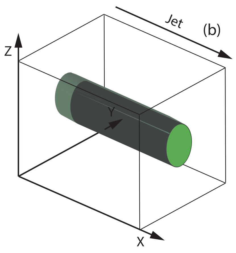
We perform “global” simulations of the injection of a cylindrical jet into an ambient plasma in order to investigate shocks (Weibel-like instabilities) and velocity shear (kKHI and MI) simultaneously. Simulations of shocks generated by the Weibel instability have previously been performed using the model shown in Figure 1a where the jet spans the computational grid in the transverse direction (e.g., Nishikawa et al. 2009a; Choi et al. 2014; Ardaneh et al. 2015). In other simulations, the kKHI and MI have been investigated using a slab jet model (not shown) (e.g., Nishikawa et al. 2013, 2014a,b,c), or a cylindrical model where the jet spans the computational grid in the longitudinal direction (Alves 2010; Nishikawa et al. 2014c) as shown in Figure 1b.
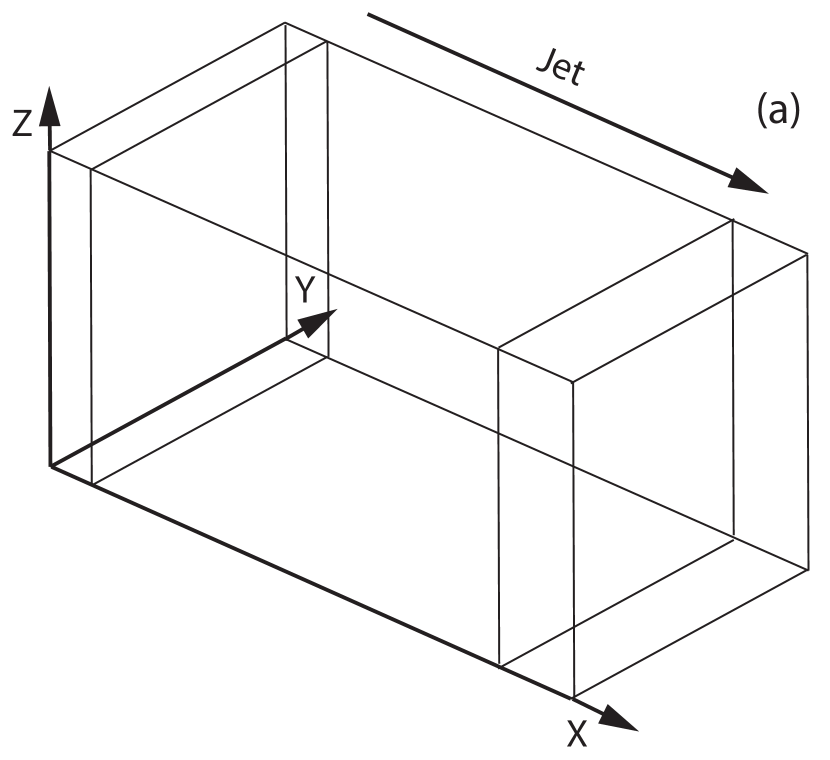
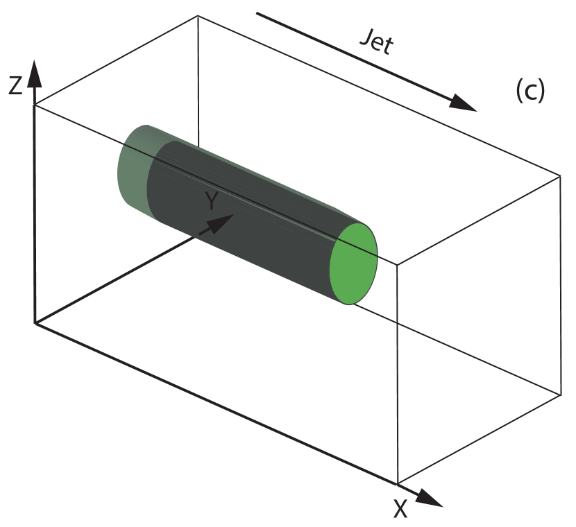
The separate investigation of leading edge shocks or velocity shear surfaces does not provide a realistic scenario for jets in most astrophysical systems. To achieve and investigate the combined effect of the leading edge shocks and velocity shear instabilities, such as might be associated with the “needles-in-a-jet” or “jet-in-a-jet” scenarios proposed in the blazar AGN context, we perform simulations of a relativistic cylindrical jet injected into an ambient plasma. Such simulations contain both a velocity shear and a shock in a potentially complicated shock/shear system, as shown in Figure 1c. We use an open boundary condition for the bottom and top (at ). In order to avoid possible artificial phenomena which may affect the initial jet evolution, we inject the jet far from the boundary at . The jet is injected with a sharp edge and the “top hat” shape. It should be noted that in the case (c) the jet is injected into the ambient plasmas therefore there is no discontinuity as in the case (b) in which the jet is set inside the ambient plasma, with a discontinuity between the two plasmas. However, the jet is injected with a sharp edge, therefore there exists some discontinuity initially at the jet boundary which excites kKHI and MI. Inside the jet the Weibel instability is excited interacting with the ambient plasma.
3.2 Cylindrical Jet Velocity Shear Result Summary
In the following we describe kKHI and MI simulation results from a cylindrical velocity shear setup as shown in Figure 1b, in order to illustrate the basic differences between and plasma jets (Nishikawa et al. 2014c). These simulations have been performed using a numerical grid with (simulation cell size: ) and periodic boundary conditions in all dimensions. The jet and sheath (electron) plasma number density measured in the simulation frame is . The cylindrical jet with jet radius is inserted in the middle of the plane. The electron skin depth, , where is the electron plasma frequency and the electron Debye length for the ambient electrons . The jet-electron thermal velocity is in the jet reference frame, where is the speed of light. The electron thermal velocity in the ambient plasma is , and ion thermal velocities are smaller by . Simulations were performed using an electron-positron () plasma or an electron-proton ( with ) plasma for the jet Lorentz factor of 5 and with the sheath plasma at rest ().
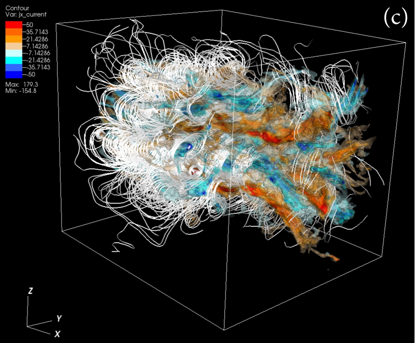
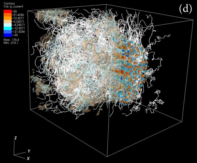
Figure 2 shows isocontour images of the component of the current along with magnetic field lines generated by the kKHI and MI for and jets.
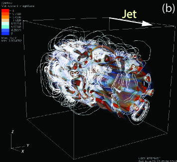
In the jet case shown in Figure 2a, currents are generated in sheet like layers and magnetic fields are wrapped around the jet. The toroidal magnetic field lines outside of the jet show signatures of both kKHI and MI (Fig. 2a). Nishikawa et al. (2014b) have shown the development of the MI mode at the earlier linear stage even they had not yet identified it as an MI. At the nonlinear stage the wavelength of MI becomes very large and DC magnetic field is generated as shown in Alves et al. (2012). In this simulation the cylindrical jet is used, the DC magnetic field becomes more eminent and related to the collimation of jet. As it is discussed in Section 2 for relativistic jets with higher Lorentz factor the MI becomes dominant compared to kKHI (Alves et al. 2015), and we believe that the MI is more likely the source for generating the DC magnetic field. On the other hand, in the jet case shown in Figure 2b, many distinct current filaments are generated near the velocity shear, and the individual current filaments are wrapped by the magnetic field which clearly indicates the MI. The clear difference in the magnetic field structure between these two cases, may make it possible to distinguish different jet compositions via differences in circular and linear polarization.
3.3 Results of 3D Global Jet Simulations
Nishikawa et al. (2014c) reported simulation results using a computation system with ), jet Lorentz factor , jet injection at and jet radius in the center of the plane. However, the jet radius in these simulations was too small to clearly distinguish velocity shear and shock effects. Here we overcome this deficiency by using a 5 times larger jet radius, , and a suitably larger computation system with ). The cylindrical jet with jet Lorentz factor is continuously injected at in the middle of the plane as shown in Figure 1c. Note that this system is short compared to previous pure shock simulations (Nishikawa et al. 2009a; Choi et al. 2014; Ardadeh et al. 2015) and reveals only the earliest stages of shock development.
The jet and ambient (electron) plasma number density measured in the simulation frame is and , respectively. The electron skin depth in the ambient medium is , and the electron Debye length for the ambient electrons is . The jet-electron thermal velocity is in the jet reference frame. The electron thermal velocity in the ambient plasma is , and ion thermal velocities are smaller by . We have chosen these thermal velocities in order to investigate the combined effect of shocks (e.g., Nishikawa et al. 2009a) and kKHI (e.g., Nishikawa et al. 2014b) with thermal temperatures similar to those used in these studies. Simulations were performed using an electron-positron plasma or an electron-proton plasma with the ambient plasma at rest (). The system evolution is followed until .
The global evolution of relativistic electron-positron and electron-proton plasma jets is shown in Figure 3.
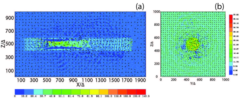
For the case jet collimation takes place at due to the toroidal magnetic fields generated by the kKHI and the MI. Jet electrons are pinched towards the jet center where current filaments merge and high electron density is created beyond . The collimation disappears gradually beyond . The jet is well defined by the heavy jet protons. The wave patterns generated by the kKHI and the MI and extending for are shown in Figures 3a and 3b. For the case, since electrons and positrons are light, there is a mix of jet and ambient particles at the velocity shear boundary as found previously using the cylindrical core sheath scheme (Nishikawa et al. 2014a,b,c). As in shock simulations (Nishikawa et al. 2009a), the Weibel instability is excited in the jet and density fluctuation patterns are generated around . At the same time the kKHI and the MI are excited in the velocity shear region causing jet and ambient electrons to move away from the jet boundary. This motion appears as the streaks in Figure 3c. The excited wave patterns are clearly exhibited in Figure 3d.
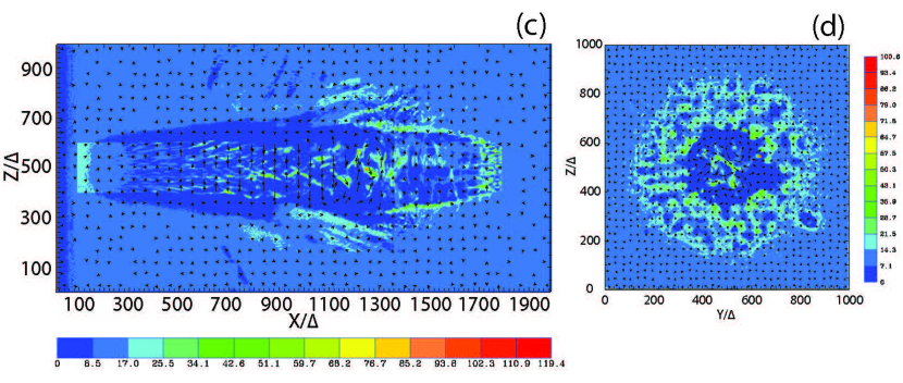
Differences between the two cases are also revealed in other physical quantities, such as the component of current density shown in Figure 4.
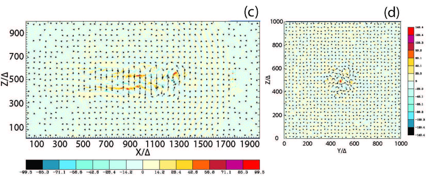
Magnetic fields in the plane are shown by lengthened arrows so that even weak magnetic fields can be seen. For the case the Weibel instability generates current filaments shown in Figure 4c that nonlinearly saturate around . In the nonlinear region electron density fluctuations are a sign of shock formation. The initial nonlinear stage (minor saturation) is seen in the merging of current filaments as also seen in the previous simulation in Nishikawa et al. (2009a). Note, however, that in order to fully establish the shock we require a grid length that is larger than (see, e.g., Nishikawa et al. 2009a). For the case, strong electron currents are generated by the high electron density in the collimation region shown in Figure 4a. The jet boundary is framed by the proton currents shown in Figures 4a and 4b. Wave patterns generated by the kKHI and MI are clearly seen as radial propagation in the plane perpendicular to the jet.
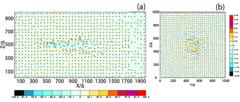
Figure 5 shows the particle phase-space (panels (a) and (c)) and the particle phase-space (panels (b) and (d)) for jet electrons (red) and ambient electrons (blue).
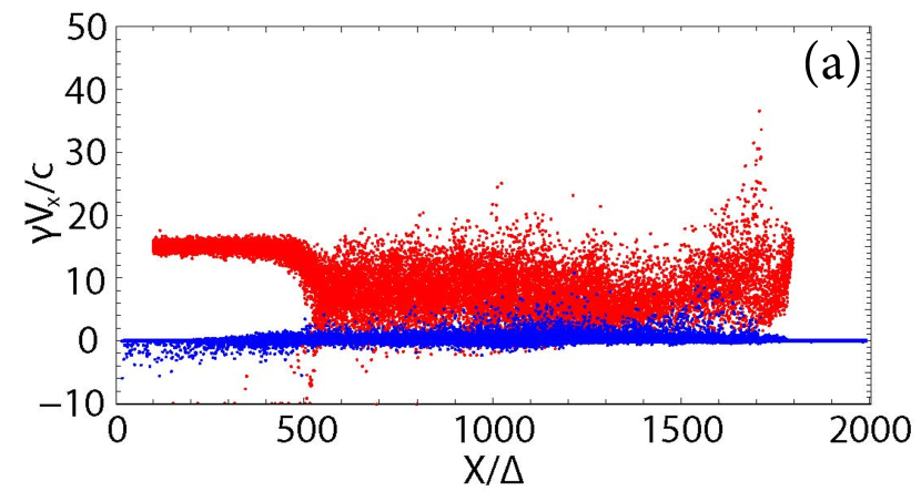

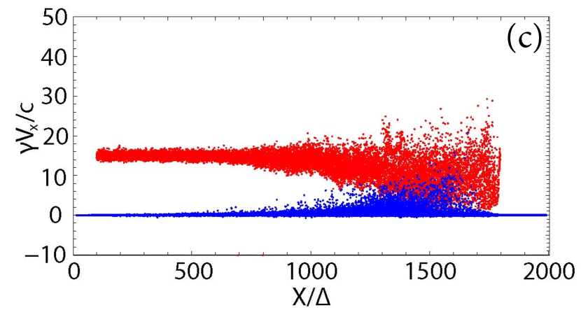
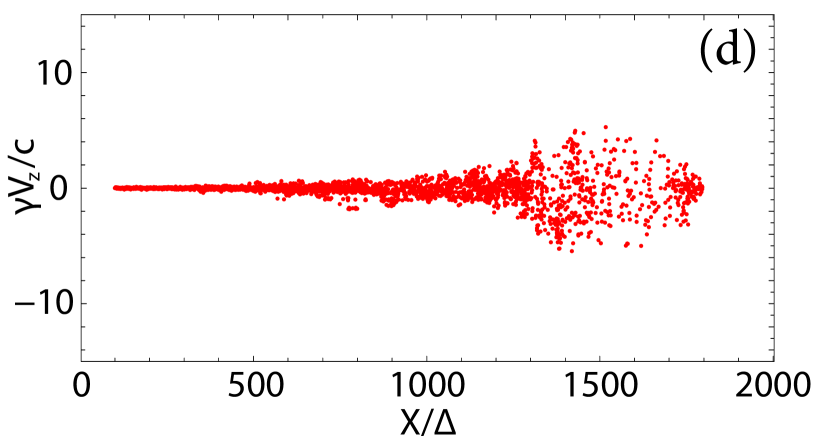
The location of jet collimation in the case is where jet electrons are strongly slowed and some jet electrons are reflected, i.e., the jet electrons have . At the collimation shock jet electrons are accelerated perpendicularly as shown in Figure 5b. Jet electrons are accelerated just behind the jet front as shown by the spike in phase space at in Figure 5a. Some ambient electrons are also slightly accelerated. The behavior of jet electrons is very similar to shock simulations (Nishikawa et al. 2009a) even though the region outside of the jet shows a complicated structure due to the excited kKHI and MI. For the case, the jet and ambient electrons are slowly accelerated by the Weibel instability. The ambient electrons are swept up as in the shock simulations (e.g., Nishikawa et al. 2009a; Choi et al. 1014; Ardaneh et al. 2015). However, due to the short simulation box the shock system has not yet fully formed.
Figure 6 shows the magnetic field strength in the plane at and in a cross section in the plane at .
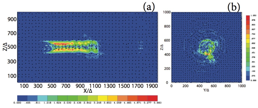
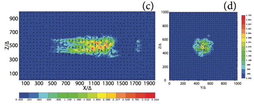
Figure 6a shows a strong magnetic field in the jet between where the electron-proton jet collimates due to strong toroidal magnetic fields. The magnetic field strength at indicates a maximum toroidal magnetic field strength at radius . The strong toroidal magnetic fields are also seen in Figs. 11a and 12a. For the case waves generated by the kKHI and the MI are visible in Figure 6b at . Strongly growing MI waves are seen at two and five clock (Fig. 6b). The layers of concentric rings around the jet seem to be generated by kKHI. For the case the strongest magnetic fields are located near where the Weibel instability grows. In the transverse plane at the jet-ambient boundary patterns induced by the MI are visible in Fig. 6d.
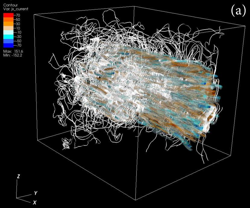
Figure 7 shows the 3D structure in the component of the current density in the jet for the case near the injection region (), in an intermediate region (), and near the jet front ().
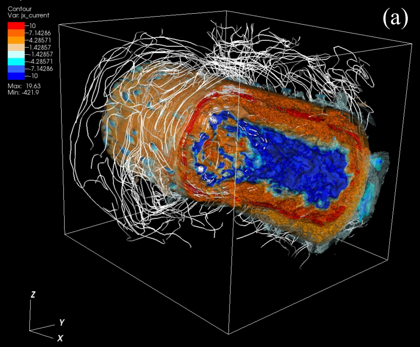
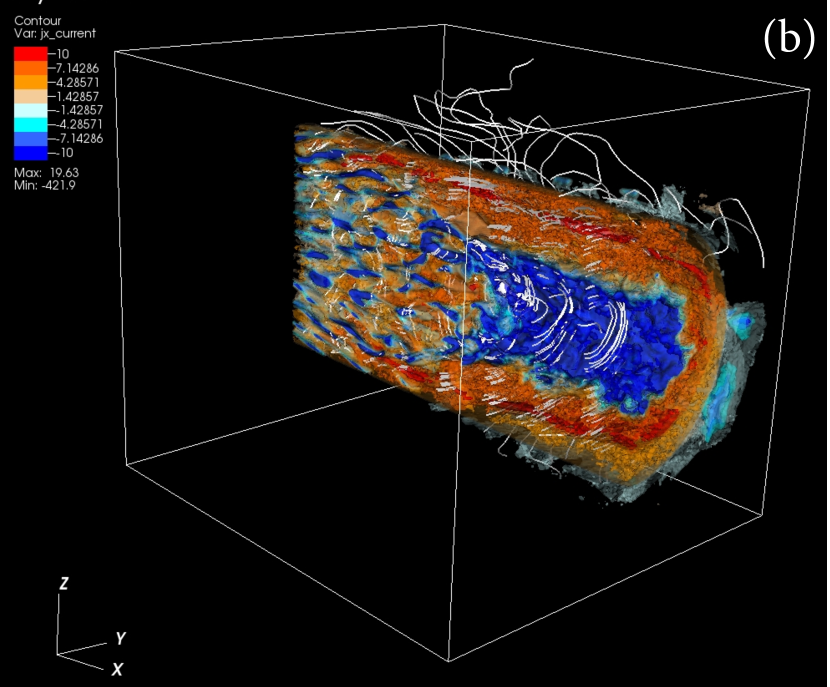
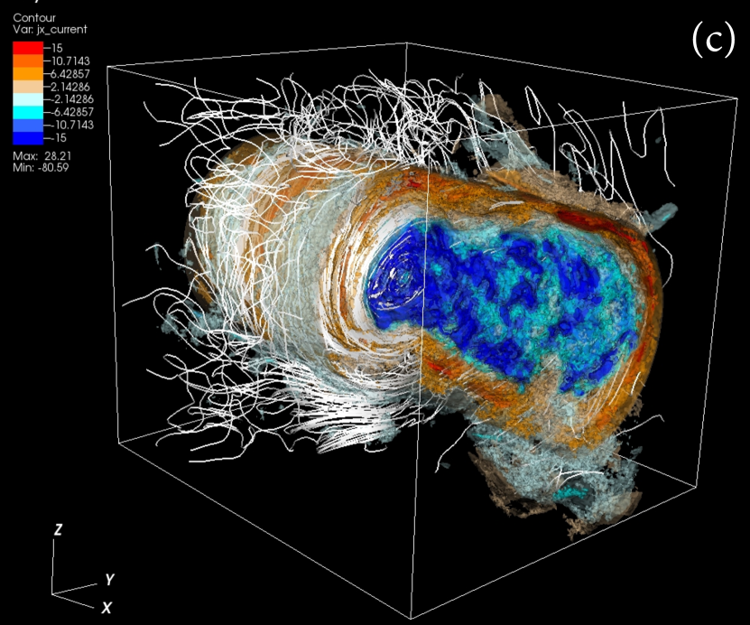
Collimation occurs near where proton current filaments merge into the uniform electron current inside the toroidal proton current shown in Figures 7a and 7b. This uniform electron current can also be seen in Figure 4a and is associated with the collimated electron density seen in Figure 3a. The collimation is generated by the strong toroidal magnetic field shown in Figure 6a. This strong toroidal magnetic field is generated by the kKHI and/or MI. Based on the growth rates shown in Figure 1 in Alves et al. (2015) the MI has much higher growth rate for . The structure of the magnetic field lines outside the jet is a signature of the MI. Since MI grows transverse to the jet, and as in the slab model the magnetic fields become DC when the current filaments merge in the nonlinear stage (see Nishikawa et al. 2014b). The strongest toroidal magnetic fields are located inside the jet surface and are hidden by the proton currents shown in red in Figures 7a and 7b. Figure 7c shows that the collimation relaxes gradually around . Current filaments and nonlinear phenomena at the jet front need further future investigation with a fully-evolved shock system.
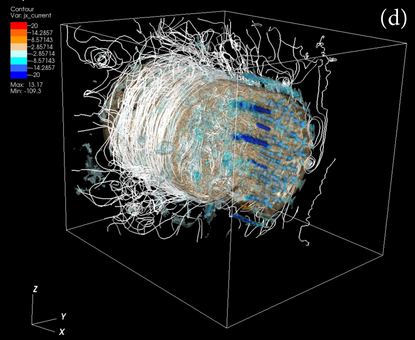
Figure 8 shows the 3D structure in the component of the current density in the jet for the case near the injection region (), in an intermediate region (), and near the jet front ().
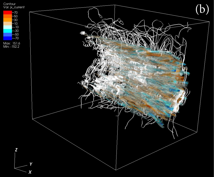
As in a previous electron-positron simulation (Nishikawa et al. 2009a), current filaments grow and in the nonlinear stage are located outside the jet as shown in Figure 8c, and merge and/or dissipate as shown in Figure 4c. After merging current filaments become weak by . This evolution is very similar to a previous simulation at the same simulation time (e.g., Nishikawa et al. 2009a). In the case, as previously found in the slab model, AC magnetic field patterns are generated at the velocity shear and no collimation occurs.
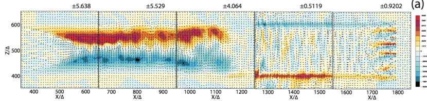
Figure 9 shows the electron density in a 2D slice through jet center for the - (upper) and (lower) at time . In order to show the electron density structure in detail, five sections are scaled separately. The minimum and maximum numbers of each panel are indicated at the right upper corner. For the - case the electron density increases at due to collimation. The collimation relaxes by and the electron density spreads to the original jet width. For the case electron density filaments are initially generated along the jet and in the nonlinear stage move outside of the jet as shown in Figures 9b and 8c.
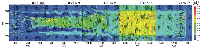
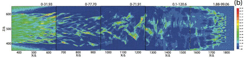
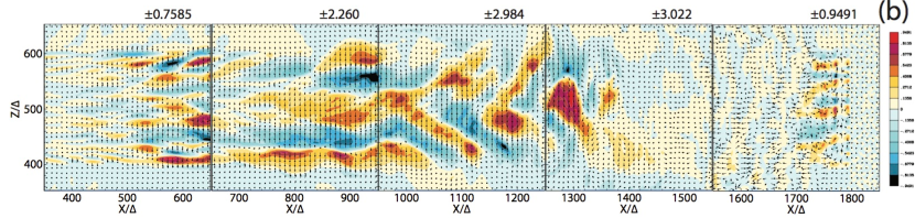
Figure 10 shows in 2D slices through jet center for the - (upper) and (lower) cases at time . For the - case strong electron currents are generated in the center of the jet consistent with the collimation shown in Figure 9a. After the collimation relaxes around proton currents become dominant at the jet boundary and the electron and proton currents become layered at . It should be noted that in the collimated region the magnetic fields shown by the arrows provide rather complex structures. For the case current filaments are initially generated along the jet and in the nonlinear stage they move out of the jet as shown in Figures 10b, 11b and 8c.
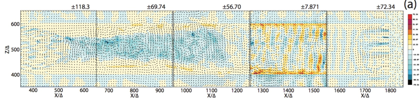
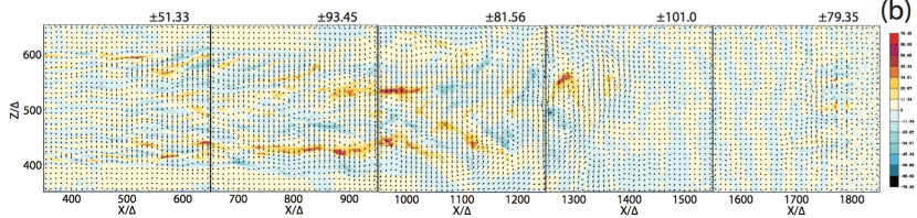
Figure 11 shows 2D slices of through the jet center for the - (upper)
and (lower) cases at time . In the - case strong toroidal magnetic fields collimate the jet. This strong toroidal magnetic field is generated by the strong by collimated jet (ambient) electrons as shown in Fig. 4a. After the collimation relaxes around the polarity of the toroidal magnetic fields switches from clockwise in the rightmost panels to counter-clockwise in the leftmost panels as viewed from the jet front. The counter-clockwise magnetic fields are generated by the current layer () at the jet boundary as shown in the right two panels in Figure 10a. Due to the perpendicularly accelerated jet electrons in the collimated region as shown in Fig. 5b, the electrons are expelled from the collimated region and are slowed down as shown in Fig. 5b. Consequently, the MI is saturated and the strong toroidal magnetic field disappears and releases the collimation. At the same time, concentrated electron current near the center of the jet brakes and jet electrons expand outward. As shown in Fig. 12b, heavy jet protons maintain the original jet border line and due to the decrease of electrons near the jet boundary current is generated, which generates the counter-clockwise magnetic field. Furthermore the patterns of MI are seen near the jet boundary.
For the case, filaments of alternating are initially generated along the jet by the current filaments and at the nonlinear stage they move out of the jet as shown in Figures 11b and 8c. For both cases at the jet front the strong striped components generated by the current filaments as shown in Figure 10, which have been observed in previous simulations of the Weibel instability (Nishikawa et al. 2009a; Ardaneh et al. 2015).
Figure 12 shows in 2D cross sections at and
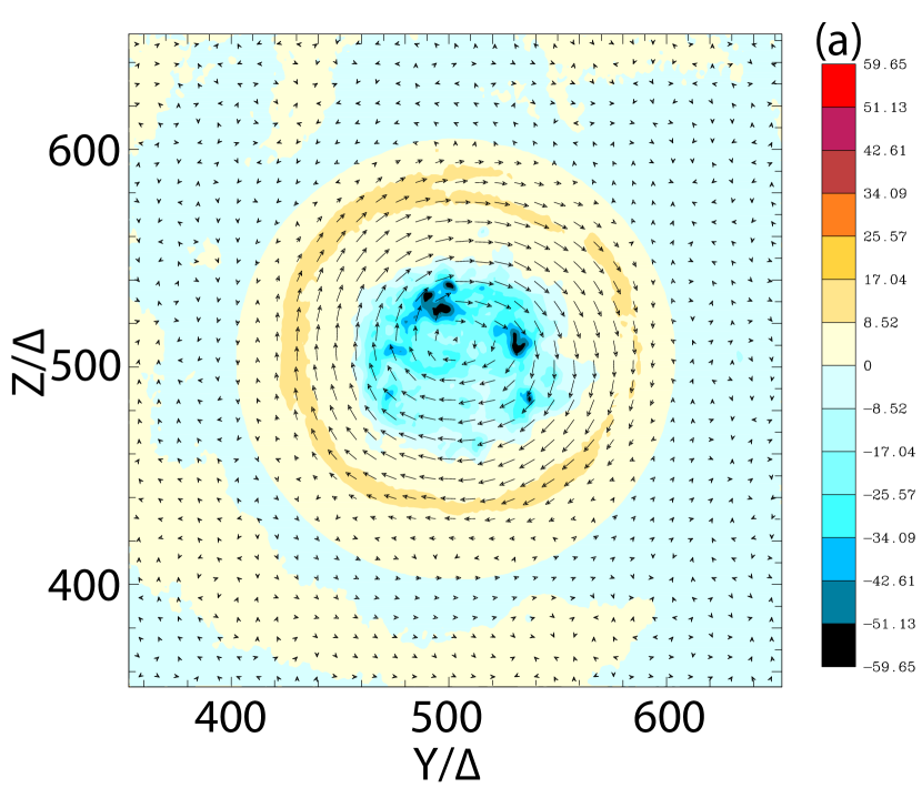
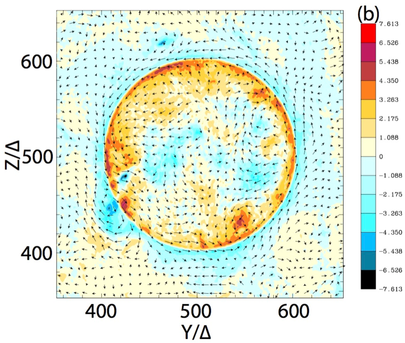
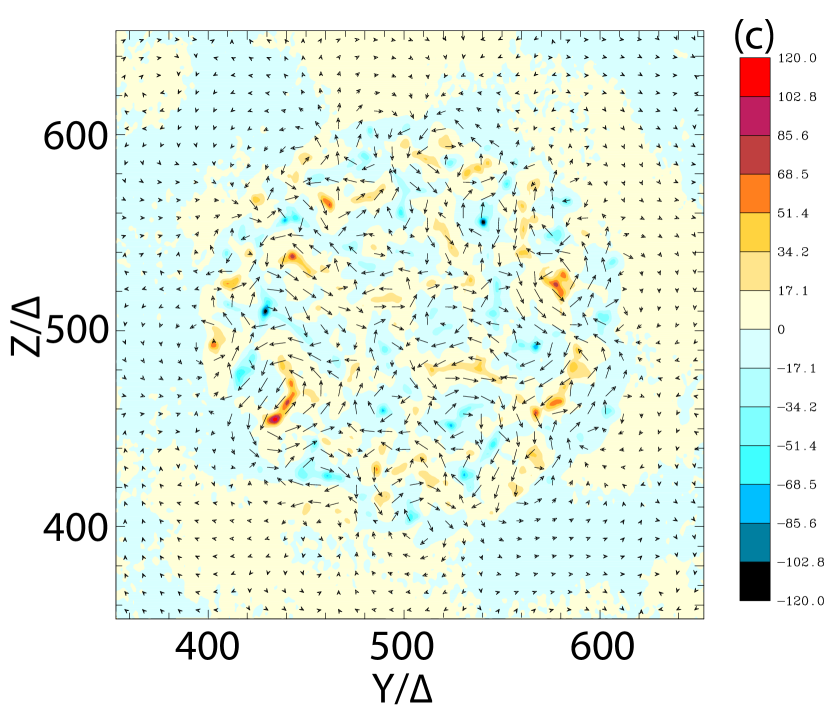
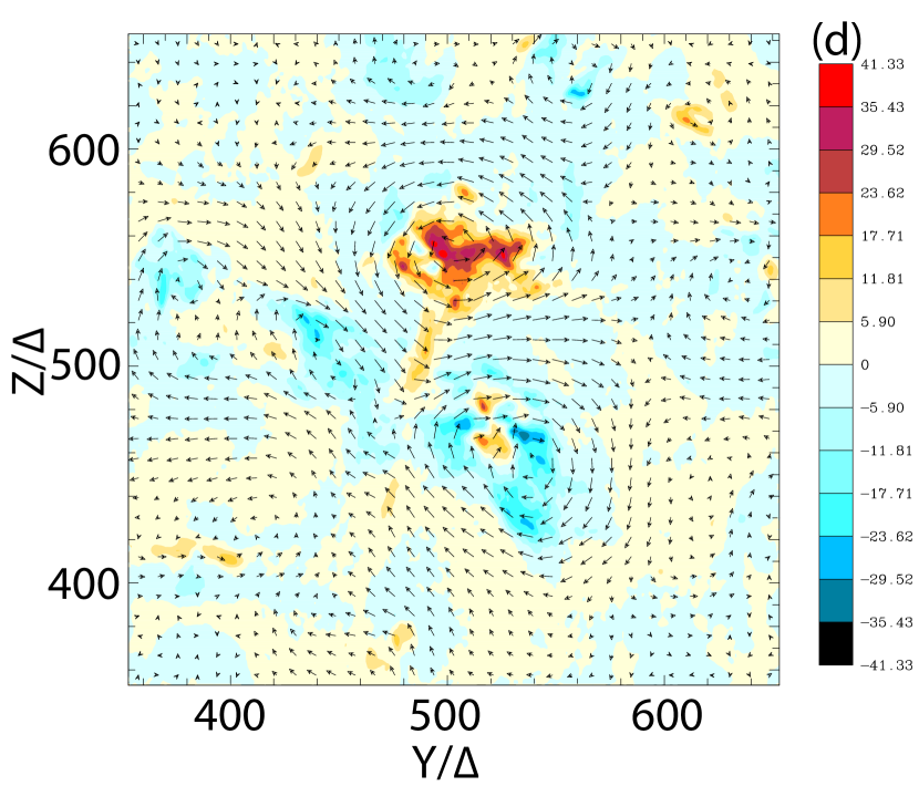
for (panels a and b) the - case and (panels c and d) the case at time . The arrows show the magnetic field in the cross section plane. For the - case at the toroidal magnetic field is clockwise and generated by the electron current in the center of the jet. Since electrons are collimated, protons move slightly toward jet center as indicated by stronger located slightly inside the original jet boundary. At the magnetic field is counter-clockwise and generated by proton dominated currents slightly inside the jet boundary. For the case shown in Figure 12c small current filaments are generated by the kKHI, the MI, and the Weibel instability. The slightly stronger current filaments around the jet boundary are likely generated by the MI. These small current filaments merge into the two larger current filaments at shown in Figure 12d.
4 Summary and Discussion
We performed simulations of a relativistic cylindrical jet that is injected into an ambient plasma in order to investigate a simultaneous velocity shear and shock system, and to study the interaction between shear instabilities (kKHI and MI) and the filamentation Weibel-like instability. The investigation of the combined processes shows very different evolution for - and plasma cases. Our jet radius and transverse grid dimensions properly reveal the different evolution associated with the velocity shear instability. However, the grid length is not long enough for the leading edge shock system to fully develop as shown in previous shock generation simulations using a much longer grid (Nishikawa et al. 2009a; Choi et al. 2014; Ardaneh et al. 2015).
The key simulation results for - plasma case are:
-
Jet electrons are collimated by strong toroidal magnetic fields generated by the MI.
-
Electrons are perpendicularly accelerated along with the jet collimation.
-
Toroidal magnetic field polarity switches from clockwise to counter-clockwise about half way down the jet.
The key simulation results for the plasma case are:
-
Jet electrons and positrons mix with the ambient plasma.
-
Magnetic fields around current filaments generated by a combination of kKHI, MI and Weibel instability merge and generate density fluctuations.
-
A larger jet radius is required to properly simulate the case since jet and ambient particles mix strongly.
Kinetic processes at the velocity shear, i.e., the kKHI and MI, lead to differences between the - and cases. Proper spatial behavior can only be investigated by the simulation setup used in this study. Due to the merging of current filaments generated by the kKHI and the MI, DC magnetic fields are generated outside the - jet. These strong toroidal magnetic fields collimate the jet electrons. After the instabilities saturate and relax, the polarity of the toroidal magnetic field switches from clockwise to counter-clockwise as shown in Figure 11a. The collimation of jet electrons is accompanied by perpendicular acceleration as shown in Figure 5b.
For the - case, interaction and magnetic fields do not extend far from the initial velocity shear surface. For the cases, interaction and magnetic fields extend farther from the initial velocity shear surface although the interaction occurs more inside the jet for higher jet Lorentz factor.
Differences in velocity shear magnetic field structure resulting from differences in composition should have consequences for the appearance of jets in very high-resolution radio imaging. For a simple cylindrical geometry velocity shear case, an electron-proton jet would primarily build toroidal magnetic field at the velocity shear surface. The magnetic field would appear quasi-parallel to the line of sight at the limbs of the jet for typical aspect angles . In contrast, a pair-plasma jet would generate sizable radial field components that are only about a factor of two weaker than the toroidal field. The strong electric and magnetic fields in the velocity shear zone will be conducive to particle acceleration as shown in Figure 5b.
Since the DC field is stronger than the AC field in the electron-proton case, a kinetic treatment is clearly required in order to fully capture the generated field structure (Alves et al. 2012). The generated field structure is important because it may lead to a distinct radiation signature (e.g., Medvedev 2000; Sironi & Spitkovsky 2009b; Martins et al. 2009; Frederiksen et al. 2010; Medvedev et al. 2011; Nishikawa et al. 2009b, 2010, 2011, 2012).
The evolution of the jet is very similar to previous jet front shock simulations (e.g., Nishikawa et al. 2009a). Since the jet length is only , the leading edge shock system is not yet fully formed, but the current filaments are merged as in the shock simulations.
The dissipation of a significant fraction of the magnetic energy, e.g., via magnetic reconnection, will naturally result in the appearance of flares when the accelerated particle beam is directed along the line of sight (Giannios et al. 2009; Komissarov et al. 2009; Zhang & Yan 2011; Nalewajko et al. 2011; Cerutti et al. 2012, Granot et al. 2012; Komissarov 2012; McKinney & Uzdensky 2012; Sironi et al. 2015). Recently, Beniamini & Granot (2015) have studied the expected prompt GRB emission from magnetic reconnection and compare its expected temporal and spectral properties to observations. Therefore, it is very important to investigate any signatures of reconnection. For example as shown in Figure 10a in the jet around and in Figure 10b around , complicated magnetic field structures may be a signature of reconnection. Future work will address this possibility.
Current and magnetic structures are very different in the electron-proton and electron positron cases. The differences arise from the different mobilities of protons and positrons. The toroidal component of the magnetic field found for the case would lead to a stratification in the emission across the jet width due to the dependence of the synchrotron emission with the angle between the magnetic field and the line of sight (e.g., Aloy et al. 2000; Clause-Brown et al. 2011). Furthermore, a toroidal magnetic field would lead to a gradient in Faraday rotation across the jet width, produced by the systematic change in the net line-of-sight magnetic field component (Laing 1981; Blandford 1993). Such gradients in Faraday rotation across the jet width have been searched for through simultaneous multifrequency polarimetric VLBI observations of AGN jets. The first detection of a Faraday rotation gradient was reported by Asada et al. (2002) based on VLBA observations of 3C273. Following this initial detection other authors have claimed similar gradients in Faraday rotation in other AGN jets (e.g., Gabuzda et al. 2004; Gómez et al. 2008; O’Sullivan & Gabuzda 2009). Hovatta et al. (2012) have studied a sample of 191 extragalactic radio jets observed within the MOJAVE program, finding significant Faraday rotation gradients in CTA102, 4C39.25, 3C454.3, and 3C273; among these sources, the most clear evidence was again obtained for 3C273, for which these authors have also found variations in the Faraday rotation screen over a timescale of three months, suggesting some internal (within the jet emitting region) Faraday rotation. Furthermore, a sign change from positive to negative Faraday rotation was observed in 3C273, that resembles the change in polarity of the toroidal field found in our electron-proton case.
More recently, Gómez et al. (2015) have investigated the Faraday rotation screen in BL Lacertae through space-VLBI observations with the RadioAstron mission. These observations, achieving an angular resolution of 20 uas (the highest obtained to date), reveal a gradient in Faraday rotation and polarization vectors as a function of position angle with respect to the core, suggesting the presence of a large-scale helical magnetic field threading the jet in BL Lacertae.
Additional work is required to explore the observational signatures of the different magnetic field properties expected for the and cases. The resulting magnetic field structures are different enough to yield distinctive polarizations in VLBI observations of AGN jets. Toroidal magnetic fields inside and outside the electron-proton jet may contribute to circular polarization (CP). VLBI observations in the MOJAVE sample have revealed CP in about 15% of the observed sources, with a level of CP of the order of 0.5% of the local total intensity (Homan & Lister 2006). Subsequent observations by Gabuzda et al. (2008) and Vitrishchak et al. (2008) of the same sources for which CP was observed in the MOJAVE sample show no disagreement in the sign of the CP, which supports the idea that the CP is indeed related to the intrinsic composition and magnetic field structure of AGN jets. Although a pair plasma cannot generate intrinsic CP, the CP obtained by Wardle et al. (1998) through VLBI observations of 3C279 is explained if the CP is produced by Faraday conversion. Faraday conversion requires a low energy cutoff in the electron energy distribution and a pair plasma is required to avoid the jet carrying more kinetic energy than observed.
In these simulations, helical magnetic fields are not included. This also is a major difference with RMHD simulations which have a helical magnetic field. Therefore the results in this study may not cover all aspects of real extragalactic jets. Nevertheless, the phenomena in this PIC simulation study are based on the kinetic effects such as kKHI and MI which are not included in RMHD simulations. For example, hot-spots in FRII jets could be explained due to particle (electron) acceleration due to kinetic instabilities. However, the size of jets in this study is very small compared to the real jets, therefore the macroscopic dynamics of jets may not be included fully. Still, it is fruitful to compare these results with parsec scale jets, but careful considerations need to be taken. We plan to perform synergistic simulation studies with RMHD, which will be reported in a separate report.
In our future simulations we will inject jets with a helical magnetic field like that implemented in Markidis et al. (2013). This configuration will allow investigation of the effect of helical magnetic fields on growth of the Weibel instability, the kKHI, and MI as well as to whether an MHD-like kink and/or a KHI velocity shear driven helical twist occurs.
References
- Aloy et al. (2000) Aloy, M.-A., Gómez, J. L., Ibáñez, J. M., Martí, J. M., & Müller, E., 2000, ApJ, 528, L85
- Alves (2010) Alves, E. P., Magnetic field generation via the Kelvin-Helmholtz Instability, 2010, Master thesis, Universidade Técnica de Lisboa
- Alves et al. (2016) Alves, E. P., Grismayer, T., Silveirinha, M. G., Fonseca, R. A., Silva, L. O., 2016, PPCF, 58, 014025
- Alves et al. (2015a) Alves, E. P., Grismayer, T., Fonseca, R. A., Silva, L. O., 2015, PhReE, 92, 1101
- Alves et al. (2014) Alves, E.P., Grismayer, T., Fonseca, R.A., & Silva, L.O., 2014, NJPh, 16, 035007
- Alves et al. (2012) Alves, E.P., Grismayer, T., Martins, S.F., Fiúza, F., Fonseca, R.A., & Silva, L.O., 2012, ApJ, 746, L14
- Ardaneh et al. (2015) Ardaneh, K., Cai, D., Nishikawa, K.-I. Lembége, B., 2015, ApJ, 811, 57
- Asada et al. (2002) Asada, K., Inoue, M., Uchida, Y., Kameno, S. Fujisawa, K Satoru Iguchi, S., & Mutoh, M., 2002, PASJ, 54, L39
- Beniamini & Granot (2015) Paz Beniamini1 and Jonathan Granot, 2015, MNRAS, submitted (arXiv:150902192)
- Blandford (1993) Blandford, R. D. 1993, in Astrophysical Jets, ed. D. Burgarella, M. Livio, & C. P. O’Dea (Cambridge: Cambridge Univ. Press), 15
- Bludeman et al. (1960) Bludeman, S.A., Watson, K.M., & Rosenbluth, M.N., 1960, Phys.Fluids, 3, 747
- Bret et a,l. (2010) Bret, A., Gremillet, L., & Dieckmann, M. E., 2010, PhPl, 17, 120501
- Choi et al. (2014) Choi, E. J., Min, K., Nishikawa, K.-I., Choi, C. R., 2014, PhPl, 21, 2905
- Clausen-Brown et al. (2011) Clausen-Brown, E., Lyutikov, M., & Kharb, P., 2011, MNRAS, 415, 2081
- Clausen-Brown et al. (2013) Clausen-Brown, E., Savolainen, T., Pushkarev, A.B., Kovalev, Y.Y. & Zensus, J.A., 2013, A&A 558, A144
- D’Angelo (1965) D’Angelo, N., 1965, PhFl, 8, 1748
- Dieckmann et al. (2008) Dieckmann, M. E., Shukla, P. K., & Drury, L. O. C., 2008, ApJ, 675, 586
- Frederiksen et al. (2010) Frederiksen, J. T., Haugbølle, T., Medvedev, M. V., & Nordlund, Å., 2010, ApJ, 722 L114
- Frederiksen et al. (2004) Frederiksen, J. T., Hededal, C. B., Haugb lle, T., & Nordlund, ., 2004, ApJ, 608, L13
- Gabuzda et al. (2004) Gabuzda, D. C., Murray, E., & Cronin, P., 2004, MNRAS, 351, L89
- Gabuzda et al. (2008) Gabuzda, D. C., Vitrishchak, V. M., Mahmud, M., & O’Sullivan, S. P., 2008, MNRAS 384, 1003
- Giannios et al. (2009) Giannios, D., Uzdensky, D. A. & Begelman, M. C., 2009, MNRAS, 395, L29
- Gómez et al. (2015) Gómez, J., Lobanov, A. P., Bruni, G., Kovalev, Y. Y., Marscher, A. P., Svetlana G. Jorstad, S. G., Mizuno, Y., Bach, U., Sokolovsky, K. V., Anderson, J. M., Galindo, P., Kardashev, N. S., & Lisakov, M. M., 2015, ApJ, in press, (arXiv:1512.04690)
- Gómez et al. (2008) Gómez, J. L., Marscher, A. P., Jorstad, S. G., Agudo, I., & Roca-Sogorb, M., 2008, ApJ, 681, L69
- Granot (2012) Granot, J., 2012, MNRAS, 421, 2442
- Grismayer et al. (2013) Grismayer, T., Alves, E. P., Fonseca, L.O., & Silva, L., 2013a, PRL, 111, 015005
- Grismayer et al. (2013) Grismayer, T., Alves, E.P., Fonseca, L.O. & Silva, L. 2013b, PPCF, 55, 124031
- Gruzinov (2008) Gruzinov, A. 2008, arXiv:0803.1182
- Hardee & Rose (1978) Hardee, P.E., & Rose, W.K., 1978, ApJ, 219, 247
- Hardee et al. (2007) Hardee, P., Mizuno, Y., & Nishikawa, K.-I., 2007, Astrophys Space Sci, 311, 281
- Hasegawa et al. (2004) Hasegawa, H., Fujimoto, M., Phan, T.-D., Reme, H., Balogh, A., Dunlop, M., Hashimoto, C., & TanDokoro, R., 2004, Nature, 430(7001), 755
- Haugbolle (2011) Haugbølle, T., 2011, ApJL, 739, L42
- Hededal et al. (2004) Hededal, C. B., Haugb lle, T., Frederiksen, J. T., & Nordlund, ., 2004, ApJ, 617, L107
- Hededal & Nishikawa (2005) Hededal, C. B., & Nishikawa, K.-I. 2005, ApJ, 623, L89
- Homan & Lister (2006) Homan, D. C. & Lister, M. L., 2006, AJ 131, 1262
- Hovotta et al. (2012) Hovatta, T., Lister, M. L., Aller, M. F., Aller, D. D., Homan, D. C., Kovalev, Y. Y., Alexander B. Pushkarev, A. B., & Savolainen, T., 2012, AJ, 144, 105
- Jaroschek et al. (2005) Jaroschek, C. H., Lesch, H., & Treumann, R. A., 2005, ApJ, 618, 822
- Johnson et al. (2014) Johnson, J. R., Simon Wing, S., & Delamere, P. A., 2014, Space Sci Rev (2014) 184:1
- Komissarov (2012) Komissarov, S. S., 2012, MNRAS, 422, 326
- Komissarov et al. (2009) Komissarov, S. S., Vlahakis, N., Königl3, A., & Barkov, M. V., 2009, MNRAS, 397, 1153
- Liang et al. (1981) Laing, R. A. 1981, ApJ, 248, 87
- Liang et al. (2013) Liang, E., Boettcher, M., & Smith, I., 2013a, ApJL, 766, L19
- Liang et al. (2013b) Liang, E., Boettcher, M., & Smith, I., 2013b, ApJL, 779, L27
- Martins et al. (2009) Martins, J.L., Martins, S.F., Fonseca R.A., & Silva, L.O., 2009, Proc. of SPIE, 7359, 73590V-1–8
- McKinney & Uzdensky (2012) McKinney, J. C., & Uzdensky, D. A., 2012, MNRAS, 419, 573
- Medvedev (2000) Medvedev, M.V., 2000, ApJ, 540, 704
- Medvedev & Loeb (1999) MedvedevM. V., & Loeb, A., 1999, ApJ, 526, 697
- Medvedev et al. (2011) Medvedev, M.V., Frederiksen, J.T., Haugbølle, T., & Nordlund, A., 2011, ApJ, 737, 55
- Miura (1984) Miura, A., 1984, JGR, 89(A2), 801
- Miura & Pritchett (1982) Miura, A., & Pritchett, P, 1982, JGR, 87(A9), 7431
- Mizuno et al. (2007) Mizuno, Y., Hardee, P., & Nishikawa, K.-I. 2007, ApJ, 662, 835
- Murphy et al. (2013) Murphy, E., Cawthorne, T.V., & Gabuzda, D.C., 2013, MNRAS, 430, 1504
- Nalewajko et al. (2011) Nalewajko, K., Begelman, M.C., Cerutti, B., Uzdensky, D.A., & Sikora, M., 2011, MNRAS, 413, 333
- Nishikawa et al. (2014c) Nishikawa, K.-I., Hardee, P., Dutan, I., et al. 2014c, 2014 Fermi Symposium proceedings - eConf C14102.1, (arXiv:1412.7064)
- Nishikawa et al. (2014b) Nishikawa, K.-I., Hardee, P. E., Duţan, I., et al. 2014b, ApJ, 793, 60
- Nishikawa et al. (2014a) Nishikawa, K.-I., Hardee, P., Mizuno, Y., et al. 2014a, in IJMP Conference Series, 28, High Energy Phenomena in Relativistic Outflows (HEPRO IV), (World Scientific Publishing Company), 1460195
- Nishikawa et al. (2013b) Nishikawa, K.-I., Zhang, B., Dutan, I., et al. 2013, Ann. Geophys., 31, 1535
- Nishikawa et al. (2012) Nishikawa, K.-I., Niemiec, J., Zhang, B., et al. 2012, in IJMP: Conference Series, 8, High Energy Phenomena in Relativistic Outflows III (HEPRO III), (World Scientific Publishing Company), 259
- Nishikawa et al. (2011) Nishikawa, K.-I., Niemiec, J., Medvedev, M., et al. 2011, AdSR, 47, 1434
- Nishikawa et al. (2010) Nishikawa, K.-I., Niemiec, J., Medvedev, M., et al. 2010, IJMP. D, 19, 715
- [Nishikawa et al. (2009a) Nishikawa, K.-I., Niemiec, J., Hardee, P. et al. 2009a, ApJ, 698, L10
- Nishikawa et al. (2009b) Nishikawa, K. -I., Niemiec, J., Sol, H., et al. 2009b, AIPCP, 1085, 589
- Nishikawa et al. (2008a) Nishikawa, K.-I., Mizuno, Y., Fishman, G.J., & Hardee, P., 2008, IJMP, D, 17, 1761
- Nishikawa et al. (2008a) Nishikawa, K.-I., Hardee, P., Hededal, C. B., & Fishman, G. J. 2006, ApJ, 642, 1267
- Nishikawa et al. (2005) Nishikawa, K.-I., Hardee, P., Richardson, G., et al. 2005, ApJ, 622, 927
- Nishikawa et al. (2003) Nishikawa, K.-I., Hardee, P., Richardson, G., et al., 2003, ApJ, 595, 555
- Ng & Noble (2006) J. S. T. Ng & Noble, R. J., 2006, PRL 96, 115006
- O’Sullivan et al. (2009) O’Sullivan, S. P., & Gabuzda, D. C., 2009, MNRAS, 393, 429
- Perucho & Lobanov (2008) Perucho, M., & Lobanov, A.P., 2008, ASP Conference Series, Vol. 386, 381
- Silva et al. (2003) Silva, L. O., Fonseca, R. A. Tonge, J. W., Dawson, J. M., Mori, W. B., & Medvedev, M. V. 2003, ApJ, 596, L121
- Sironi et al. (2015) Sironi, L., Petropoulou, M., & Giannios, D., 2015, MNRAS, 450, 183
- Sironi & Spitkovsky (2009a) Sironi, L., & Spitkovsky, A., 2009a, ApJ, 698, 1523
- Sironi & Spitkovsky (2009b) Sironi, L., & Spitkovsky, A., 2009b, ApJ, 707, L92
- Sironi, Spitkovsky & Arons (2013) Sironi, L., Spitkovsky, A., & Arons, J., 2013, ApJ, 771, 54
- Spitkovsky (2008a) Spitkovsky, A. 2008a, ApJ, 673, L39
- Spitkovsky (2008b) Spitkovsky, A. 2008b, ApJ, 682, L5
- Vitrishchak et al. (2008) Vitrishchak, V. M., Gabuzda, D. C., Algaba, J. C., Rastorgueva, E. A., O’Sullivan, S. P., & O’Dowd, A., 2008, MNRAS 391, 124
- Walg et al. (2013) Walg, S., Achterberg, A., Markoff, S., Keppens, R., & Meliani, Z., 2013, MNRAS, 433, 1453
- Wardle et al. (1998) Wardle, J. F. C., Homan, D. C., Ojha, R., & Roberts, D. H., Nature, 395, 457
- Wardle (1998) Wardle, J. F. C., 2013, EPJ Web of Conferences 61, 06001
- Weibel (1959) Weibel, E. S. 1959, Phys. Rev. Lett., 2, 83
- Zhang & Yan (2011) Zhang, B., & Yan, H., 2011, ApJ, 726, 90
- Zhang, MacFadyen, & Wang (2009) Zhang, W., MacFadyen, A., & Wang, P., 2009, ApJ, 692, L40