Coupling of a nano mechanical oscillator and an atomic three-level medium
Abstract
We theoretically investigate the coupling of an ultracold three-level atomic gas and a nano-mechanical mirror via classical electromagnetic radiation. The radiation pressure on the mirror is modulated by absorption of a probe light field, caused by the atoms which are electromagnetically rendered nearly transparent, allowing the gas to affect the mirror. In turn, the mirror can affect the gas as its vibrations generate opto-mechanical sidebands in the control field. We show that the sidebands cause modulations of the probe intensity at the mirror frequency, which can be enhanced near atomic resonances. Through the radiation pressure from the probe beam onto the mirror, this results in resonant driving of the mirror. Controllable by the two photon detuning, the phase relation of the driving to the mirror motion decides upon amplification or damping of mirror vibrations. This permits direct phase locking of laser amplitude modulations to the motion of a nano-mechanical element opening a perspective for cavity-free cooling through coupling to an atomic gas.
pacs:
07.10.Cm, 42.50.Gy, 42.50.WkI Introduction
The manipulation of an ever more diverse variety of nano-mechanical oscillators Poot and van der Zant (2012) using the intricate control over electromagnetic fields provided by quantum optics is the subject of quantum opto-mechanics Aspelmeyer et al. (2014); Kippenberg and Vahala (2007). Interfacing light-fields in tailored quantum states with mechanical systems deeply in the quantum regime promises applications in quantum information transfer between different spectral realms Bochmann et al. (2013), studies of the quantum-classical transition Buchmann and Stamper-Kurn (2014) as well as new impulses for fundamental physics Pikovski et al. (2012), predominantly gravitational wave detection McClelland et al. (2011); Sawadsky et al. (2015).
A key benefit of nano-mechanical systems is their coupling to electromagnetic radiation over a wide range of the spectrum. This facilitates interfacing with diverse quantum devices, such as optical cavities Aspelmeyer et al. (2014), Josephson circuits Pirkkalainen et al. (2015) or quantum dots Montinaro et al. (2014) in hybrid setups. A newly emerging group of hybrid setups involves atomic or molecular systems Camerer et al. (2011); Hammerer et al. (2010); Genes et al. (2011); Bariani et al. (2014a); Hammerer et al. (2009); Singh and Meystre (2010); Singh et al. (2008); Bariani et al. (2014b); Genes et al. (2009); Dantan et al. (2014); Vogell et al. (2015); Zhang et al. (2014). They enable the exploitation of the versatile toolkit of cold atom quantum manipulations for the control of mechanical systems. Recent work has established that coupling internal states of atomic or molecular ensembles to nano-mechanical oscillators yields intriguing features, such as atom-mirror entanglement Hammerer et al. (2009); Singh and Meystre (2010) and mechanical squeezing Singh et al. (2008).
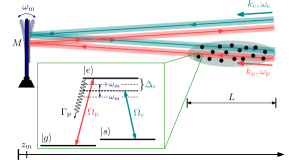
Here we present a novel scheme to affect nano-mechanical oscillators in the classical regime that does not require a cavity, in contrast to many of the proposals listed above. Instead, control of the mechanical motion of a mirror is achieved by coupling it to an ultra-cold gas with running wave laser fields Camerer et al. (2011); Hammerer et al. (2010); Vogell et al. (2015). In our case, the atoms from the cold gas interact with two laser beams under the condition of electro-magnetically induced transparency (EIT) Fleischhauer et al. (2005), as sketched in Fig. 1. An EIT control beam is reflected by the mirror before interacting with the atomic gas. Any vibrations of the mirror imprint a phase modulation onto this EIT control beam, producing side-bands of the control field detuned by the mirror frequency. This causes a modulation of the intensity of the transmitted probe beam with the mirror frequency. This effect is maximal when the mirror frequency matches the energy gap between two atomic eigenstates. The probe beam causes driving of the mirror at its resonance frequency through radiation pressure. Whether this driving amplifies or damps the mirror motion depends on the relative phase shift between probe beam amplitude modulations and mirror oscillation.
We show that this relative phase shift can be adjusted by choice of the overall two-photon detuning of the EIT lasers. At the semi-classical level discussed here, the scheme allows phase-locking the amplitude modulations of a laser to motion of a mechanical element. Equivalently, the atomic cloud allows the conversion of phase-modulations of one light-field (the control beam), into amplitude modulations of another (the probe beam).
This article is organized as follows: In section II we discuss our setup of mirror, atomic cloud and light fields followed by the physical model describing this arrangement in section III. Subsequently we analyse the dynamical response of the system, first of the atomic medium to a constantly oscillating mirror, section IV.1, and then of the mirror being driven by the response of that medium, section IV.2. In section IV.3 we investigate in which parameter regime the ensuing coupling between mirror and medium shows prospects for manipulations of the mirror, before concluding in section V.
II Setup
Our atom-optomechanical setup consists of an ensemble of trapped, non-interacting ultra cold atoms, coupled to a mirror of mass , see Fig. 1. The centre of mass position of the mirror may oscillate around its equilibrium position with frequency . For the atoms, we consider three relevant internal electronic states, , and . The states , are long-lived meta-stable ground states, while decays to with a rate , as sketched in the inset of Fig. 1. Each of two laser beams pass through the atom cloud and reflects once from the mirror. The probe beam (wavenumber , frequency ) couples the states and resonantly with Rabi frequency . It passes through the atomic cloud before reflecting off the mirror and leaving the system. The control beam (wavenumber , frequency ) couples the states and with Rabi frequency and detuning . In contrast to the probe beam, it reflects off the mirror first, then passes through the cloud and finally leaves the system.
A central feature of our setup is that the two light beams are operated under typical conditions for EIT, . At the EIT resonance , atoms in the medium settle into a so called dark state, , in which excitation to the decaying state is suppressed through quantum interference, causing the gas to become transparent for the probe beam Fleischhauer et al. (2005). Since this transparency is a subtle quantum interference phenomenon it constitutes a sensitive probe allows sensitive probing of the coupling to the mechanical oscillator, which perturbs the EIT conditions and therefore is expected to have a noticeable effect.
Since the control beam is reflected off the vibrating mirror surface, the time dependent boundary condition on its electromagnetic field causes a modulated Rabi-frequency
| (1) |
which will provide the desired perturbation of perfect EIT conditions. In the last step of (1) we assume that the mirror displacement is small compared to the optical wavelength, although this simplification is not crucial for the physics described later. For constant harmonic motion of the mirror, , the power spectrum of the control Rabi frequency acquires sidebands as in multi-chromatic EIT Wanare (2006); Li et al. (2006); Li-Jun et al. (2010); Hong-Ju et al. (2008); Zhang et al. (2007). We will show that the phase modulation of the control fields causes a time-dependent modulation of the transmission of the probe beam through the medium, or in short, the phase modulation of the control beam is turned into an amplitude modulation of the probe beam.
Due to the radiation pressure exerted by the probe beam on the mirror, we obtain a closed feedback loop, where the running wave fields are used to separately mediate the two directions of mutual coupling between the nano-mechanical mirror and the EIT medium.
III Model
We now formalise the setup presented in the preceding section, treating the light fields and the mirror classically, but the atomic EIT medium quantum-mechanically. This is valid for sufficiently large amplitudes of mirror motion compared to the zero-point motion, and optical fields that are sufficiently coherent and intense to neglect quantum fluctuations.
III.1 Mirror
The classical mirror is described by Newton’s equation for a driven harmonic oscillator
| (2) |
where is the external driving force due to the radiation pressure by the probe and control beams given by
| (3) |
The power of the probe beam reflecting off the mirror may be time dependent due to varying transmission properties of the atomic medium. In contrast the reflected control beam power is constant as the beam only passes the medium that could absorb it after reflection off the mirror.
Under conditions of perfect EIT, that is and without modulations of the coupling beam, the reflected probe beam power would be the incoming probe beam power . However, since the control beam modulates the transmission properties of the atomic medium, the probe beam power impinging on the mirror will be a function of the incoming probe beam power and time, i.e. . To determine the function , we have to study the atomic medium, which is described in section III.2.
The model could easily be extended to include intrinsic damping and driving of the mirror induced by its coupling to a thermal environment at a finite temperature due to the mirror clamping.
III.2 Atomic medium
The atomic medium consists of non-interacting atoms at positions . The interaction of each atom with the two laser beams is described in the dipole- and rotating wave approximation by the internal Hamiltonian
| (4) |
where transition operators act on atom only.
The density matrix for the ’th atom, evolves according to a Lindblad master equation
| (5) |
where the super-operator describes spontaneous decay of atom from level to Drake (2005); foo , and thus with decay operator .
Since the light fields causing the couplings in Eq. (4) are affected by the response of the atoms in the medium through which they propagate, Eq. (5) has to be solved jointly with the optical propagation equations for the light fields (Maxwell-Bloch equations). However, it is known that for c.w.-fields, the medium settles into a steady state beyond some initial transient time, providing an optical susceptibility for the probe beam, where is the transition dipole moment of the probe transition and the collective atomic coherence. In the linear regime and for a homogeneous complex susceptibility the transmitted power through a medium of length is , where is the incoming power (we split complex numbers as into real part and imaginary part ).
For the setup in Fig. 1 the phase modulation (1) of the control Rabi frequency precludes a genuine steady state. However, if the modulation period is slow enough compared to the time it takes probe beam phase-fronts to pass through the medium, we can nonetheless obtain a simple response of the medium, as argued in appendix A. The medium is then described by a time-dependent susceptibility with . Here, is determined from the solution of Eq. (5) for a single atom standing representative for the entire medium, and is the density of the medium. For this solution of (5) including coupling to the mirror, we assume the following probe power to impinge on the mirror:
| (6) |
with , where we have used the optical depth of the medium. This specifies the function of section III.1.
III.3 Light fields
The semi-classical model of the preceding two sections treats the propagating probe and control beams as classical electro-magnetic fields. It further neglects the travel time of optical beams between mirror and all atomic positions in the atom cloud, which hence has to be much shorter than the dynamical time scale of the problem that we study. The latter time-scale is given by the mirror period , so that the above assumptions are well satisfied for mirrors with frequencies in the MHz-GHz range and typical optical path lengths.
IV Vibrating mirror coupled to atomic cloud
In the following we analyse the consequences of coupling a vibrating mirror to an atomic -type EIT medium with the model developed in section III. In a first step, we take into account the phase-modulation of the control beam by the vibrating mirror, but neglect all radiation pressure on the mirror. This yields an analytically solvable time-periodic model, presented in section IV.1. In a second step, we close the feedback loop by incorporating radiation pressure on the mirror. As shown in section IV.2 this gives rise to interesting dynamics, which can be understood using the results of section IV.1.
IV.1 Time-periodic model
If the driving force is neglected in Eq. (2), the mirror will undergo harmonic oscillations with amplitude . These oscillations give rise to constant strength sidebands in the control light field , with relative amplitude . This prevents the atomic system (5) from settling into a genuine steady state, which suggests the construction of an asymptotic solution in terms of Fourier components of the density operator: , see for example Ref. Wanare (2006). For long times () we demand the Fourier amplitudes to become steady
| (7) |
Due to the presence of sidebands, Eq. (7) and Eq. (5) create an infinite hierarchy of coupled equations for the . We truncate the hierarchy at second order by neglecting all with , in what amounts to a first order perturbative expansion in . We thus keep only a constant density operator and its first harmonics at the mirror frequency ,
| (8) |
We are now interested in modulations of the imaginary part of the probe coherence (as before we split complex numbers as into real part and imaginary part ). These modulations will affect absorption by the medium according to Eq. (6). We define
| (9) |
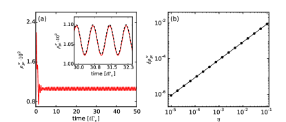
where now is the relative phase between absorption modulations and mirror motion and is the (real) amplitude of such modulations.
From our solution of Eq. (7) we find
| (10) |
where we have defined scaled quantities as and expanded to first order in , requiring and , which amounts to typical EIT conditions. From (10) we can determine and in (9) as and , where is the argument of the complex number . Here, we have used the expansion (8) and the fact that .
Fig. 2 (a) demonstrates that Eq. (10) correctly describes the long-term evolution of the atomic system. We show from a numerical solution to the master equation (5) with Newton’s equation (2), ignoring the driving force in Eq. (2) (), but initialising mirror oscillations with . This numerical solution is compared with the predictions of Eq. (9) and Eq. (10). After an initial transient phase of the full model until , the probe coherence is modulated at the mirror frequency with amplitude and phase described by Eq. (10). The modulation scales linearly with , justifying our early truncation of the hierarchy resulting from (7). Note that any mean coherence is nearly suppressed ().
Through changes in radiation pressure, the periodic modulation of the transparency of the atomic medium just discussed will give rise to a periodic driving of the mirror through Eq. (6). This driving is automatically resonant. By determining the phase-relation between driving and mirror motion as well as the amplitude of this driving, we can predict the response of the mirror from classical mechanics. To this end we plot in Fig. 3 and of Eq. (9) according to Eq. (10) for various mirror frequencies and detunings . The amplitude is maximal approximately at , with
| (11) |
as shown in Fig. 3 (a) as red dashed line. Eq. (11) is valid when is small compared to other energies. We can further expand Eq. (11) in the quantities and , which are small for cases considered here and get the even simpler expression
| (12) |
which we will exploit in section IV.3.
We can also see in Fig. 3 that a wide range of relative phases between the amplitude modulation of the probe beam, and the phase modulation of the control beam (or mirror motion) can be accessed through variations of the detuning .
The physical origin of the sharp features in Fig. 3 is a resonance between the mirror frequency and energy gaps in the atomic system. To see this, let us decompose (4) for one atom as , where the perturbation is , with and . Let us define eigenstates of via . We now assume the system has relaxed into the EIT ground-state, , but otherwise we ignore spontaneous decay here.
It is clear that whenever for some , the perturbation will cause resonant transitions to . This is the case for fulfilling (12). Since in this scenario the superposition of and will beat at the mirror frequency, also is modulated with . We have confirmed this picture using time-dependent perturbation theory.
IV.2 Interacting mirror and atomic cloud
Based on the previous section, we now determine the consequences of enabling feedback from the atomic medium onto the mirror through varying radiation pressure forces in Eq. (2) and Eq. (3). We only consider radiation pressure from the modulated part of the probe beam,
| (13) |
thereby assuming that the mirror is already oscillating around a new equilibrium position
| (14) |
due to the radiation pressure by the control beam and the constant part of the probe beam. For simplicity we set from now on.
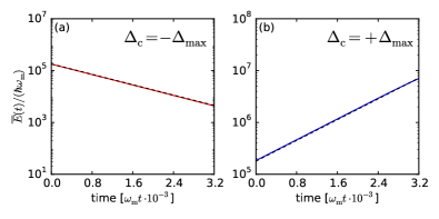
Using the driving force (13), we numerically solve the coupled Newton equation (2) and master equation (5). As can be seen in Fig. 4, the mirror can be driven such that its oscillation amplitude increases or decreases depending on . For a more quantitative description, we make the Ansatz , where the amplitude is expected to vary very little during one mirror period . The average energy of the oscillator per period is .

Inserting the Ansatz into Eq. (2), exploiting the slow variation of and using Eq. (13), we find the solution
| (15) | ||||
| (16) |
where the overline denotes a time average over one mirror period. Details are shown in appendix B. In (16), we use and can be determined from (10). Note that depending on the relative phase shift between mirror motion and transparency modulations, the quantity can actually describe damping or amplification. In Fig. 3 we see that the effect on the mirror will be largest at the resonant feature near , with damping for negative detuning and amplification for positive detuning as long as . For the two phenomena are swapped.
We validate the model (15) by comparing the predicted energy of a driven oscillator, using the analytical result for the atomic coherence (10), with the energy from a full numerical solution of Newton- (2) and master equation (5). We find good agreement as shown in Fig. 4.
The results of the present section suggest an optical technique that makes use of atomic absorption to obtain a tailored optical driving force in order to control the mechanical state of a vibrating mirror.
IV.3 Range of applicability
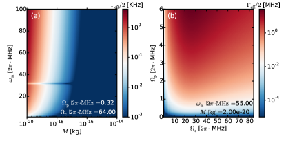
For given oscillator parameters and , the results of the preceding sections enable us to determine optical EIT parameters , , for which the damping or amplification of the mirror is maximal (Eq. (11)). For these we show the effective damping rate of (16) in Fig. 5 for a variety of mirror parameters. Additionally, we also show the performance as a function of for fixed mirror parameters.
Crucially underlying Fig. 5 are our assumptions for light-field and medium properties. We have assumed a 87Rb medium of density and length . Assigning the states , and , the Rabi-frequencies used in Fig. 5 then roughly correspond to powers and at beam waists of for the probe- and for the control beam. The transition frequencies used are . The decay rate .
For this set of parameters, cooling rates in excess of typical environmental coupling strengths are accessible for rather light mirrors with frequencies . Note that the feature at is due to the absence of atomic response at this frequency, as evident in Fig. 3 (a). Larger damping rates for heavier mirrors could be obtained with a larger probe power . In the present scheme, they are restricted by the requirement . Variations of the scheme can be achieved by choosing a higher lying decaying state , which would decrease the transition matrix element and thus allow larger for identical Rabi frequency . However, simultaneously this would typically reduce the decay rate .
V Conclusions and outlook
We have described an interface of the classical motion of a harmonically oscillating nano-mechanical mirror with the internal state dynamics and hence optical properties of a three-level, -type atomic medium. Our atom-optomechanical setup exists in free-space, without any cavity. Coupling between mirror and atomic system is provided by the probe and control light fields that render the ultra cold atomic gas transparent, due to electro-magnetically induced transparency (EIT).
Depending on the choice of the EIT two-photon detuning, amplitude modulations of the probe light beam caused by the atomic medium are phase locked to the mirror oscillation. We have provided analytical expressions for the dependence of phase and strength of the modulations on the detuning. The setup can also be seen as transferring phase modulations on one optical beam onto amplitude modulations of another.
When the modulated probe beam is made to interact with the mirror, oscillatory motion of the latter can be damped or amplified. We derive the effective damping (amplification) rate of the mirror, using a single atom type description of the EIT medium and a Fourier expansion of the density matrix in the presence of constant sidebands. The achievable damping rates exceed typical coupling strength of mirror to their thermal environment for light and fast mirrors ( kg, ).
Our results provide the basis for a thorough understanding of the corresponding quantum-mechanical setup, which appears as a good candidate for a cavity-free cooling scheme Camerer et al. (2011); Vogell et al. (2015), that may complement established cavity cooling techniques Aspelmeyer et al. (2014); Kippenberg and Vahala (2007); Marquardt et al. (2007); Wilson-Rae et al. (2007). This will be the subject of future work.
Further interesting perspectives arise when our setup is extended towards Rydberg physics: EIT media where the second ground state is replaced by a highly excited (and therefore also long-lived) Rydberg state Friedler et al. (2005); Mohapatra et al. (2007); Mauger et al. (2007); Mohapatra et al. (2008); Schempp et al. (2010); Sevinçli et al. (2011a); Parigi et al. (2012), have recently been used for the creation of single-photon sources Dudin and Kuzmich (2012); Peyronel et al. (2012) and proposed to enable nonlocal nonlinear optics Sevinçli et al. (2011b). Much of the physics presented here is similar if is replaced by a Rydberg state . Since this state would be highly sensitive to interactions with other Rydberg atoms, the control of mirror motion by further quantum mechanical atomic elements may be feasible also without an optical cavity.
Acknowledgements.
We gratefully acknowledge fruitful discussions with Yogesh Patil, Klemens Hammerer, Swati Singh, Igor Lesanovsky and Thomas Pohl, and EU financial support received from the Marie Curie Initial Training Network (ITN) COHERENCE”.Appendix A Simplified optical response
For the system shown in Fig. 1, the probe and control beams are coupled to an atomic medium with Rabi frequencies and . We assume the control field propagates inside the gas with group velocity and it is thus undisturbed by the response of the atoms Gorshkov et al. (2007). The evolution of the probe field is however determined by a wave equation in the presence of a source. This source is the medium polarization at the probe field frequency, , given as the sum of its positive () and negative () frequency parts, respectively. For a one dimensional description of the medium along , the polarization is given by the collective slowly varying atomic coherence between and , , via , where . Then within the slowly varying envelope approximation (SVEA) Boyd (2003) the wave equation for the probe field reads
| (17) |
Eqs. Eq. (17) and Eq. (5) form the so called set of Maxwell-Bloch equations.
Under usual stationary conditions of EIT one considers cw. probe and control light fields impinging on the medium. It is then assumed that locally the density matrix elements settle into their steady state determined from in Eq. (5). Assuming a linear and homogeneous response of the medium we can define . The propagation Eq. (17) can now be analytically solved from to to yield
| (18) |
under the condition . Here denotes the Rabi frequency of the incoming probe beam, while is that after passing through the medium of length .
In our scenario the control beam has a residual time-dependence at the mirror frequency, as a result the probe beam is also modulated in time. As long as the propagation of the probe beam adiabatically follows the time evolution of the coupling beam, we can assume a modulated steady state to be locally attained everywhere in the medium, according to Eq. (7). Considering the case in which retardation effects are negligible, , we then integrate again Eq. (17) from to to obtain a simple probe beam transmission through the medium as
| (19) |
For this, we assumed a linear response , where is independent of . This linearity was explicitly confirmed for cases considered here.
Appendix B Effective damping of mirror’s oscillation amplitude
The dynamics of the nano-mirror oscillations can be recast in terms of the complex variable , with the canonical momentum associated to the displacement coordinate . Newton’s equation (2) is then equivalent to , and damping and amplification of the nano-mirror motion will be reflected in the time evolution of its mechanical energy, . Written in units of length and neglecting fast rotating terms (), the time evolution of the amplitude of motion of the mirror, , reads
| (20) |
Here , and are derived in section IV.1 for constant mirror oscillations. Since the amplitude of mirror oscillations is now allowed to change in time, we make the replacement in Eq. (20), where we used the linear dependence of on the mirror oscillation amplitude found in section IV.1. The relative phase does not depend on and hence remains constant.
References
- Poot and van der Zant (2012) M. Poot and H. S. van der Zant, Phys. Rep. 511, 273 (2012).
- Aspelmeyer et al. (2014) M. Aspelmeyer, T. J. Kippenberg, and F. Marquardt, Reviews of Modern Physics 86, 1391 (2014).
- Kippenberg and Vahala (2007) T. Kippenberg and K. Vahala, Opt. Express 15, 17172 (2007).
- Bochmann et al. (2013) J. Bochmann, A. Vainsencher, D. D. Awschalom, and A. N. Cleland, Nature Physics 9, 712 (2013).
- Buchmann and Stamper-Kurn (2014) L. F. Buchmann and D. M. Stamper-Kurn, Ann. Phys. 527, 156 (2014).
- Pikovski et al. (2012) I. Pikovski, M. R. Vanner, M. Aspelmeyer, M. S. Kim, and Č. Brukner, Nature Physics 8, 393 (2012).
- McClelland et al. (2011) D. McClelland, N. Mavalvala, Y. Chen, and R. Schnabel, Laser and Photonics Reviews 5, 677 (2011).
- Sawadsky et al. (2015) A. Sawadsky, H. Kaufer, R. M. Nia, S. P. Tarabrin, F. Y. Khalili, K. Hammerer, and R. Schnabel, Phys. Rev. Lett. 114, 043601 (2015).
- Pirkkalainen et al. (2015) J.-M. Pirkkalainen, S. Cho, F. Massel, J. Tuorila, T. Heikkilä, P. Hakonen, and M. Sillanpää, Nature Comm. 14, 6981 (2015).
- Montinaro et al. (2014) M. Montinaro, G. Wüst, M. Munsch, Y. Fontana, E. Russo-Averchi, M. Heiss, A. Fontcuberta i Morral, R. J. Warburton, and M. Poggio, Nano Letters 14, 4454 (2014).
- Camerer et al. (2011) S. Camerer, M. Korppi, A. Jöckel, D. Hunger, T. W. Hänsch, and P. Treutlein, Phys. Rev. Lett. 107, 223001 (2011).
- Hammerer et al. (2010) K. Hammerer, K. Stannigel, C. Genes, P. Zoller, P. Treutlein, S. Camerer, D. Hunger, and T. W. Hänsch, Phys. Rev. A 82, 021803(R) (2010).
- Genes et al. (2011) C. Genes, H. Ritsch, M. Drewsen, and A. Dantan, Phys. Rev. A 84, 051801 (2011).
- Bariani et al. (2014a) F. Bariani, J. Otterbach, H. Tan, and P. Meystre, Phys. Rev. A 89, 011801(R) (2014a).
- Hammerer et al. (2009) K. Hammerer, M. Aspelmeyer, E. S. Polzik, and P. Zoller, Phys. Rev. Lett. 102, 020501 (2009).
- Singh and Meystre (2010) S. Singh and P. Meystre, Phys. Rev. A 81, 041804(R) (2010).
- Singh et al. (2008) S. Singh, M. Bhattacharya, O. Dutta, and P. Meystre, Phys. Rev. Lett. 101, 263603 (2008).
- Bariani et al. (2014b) F. Bariani, S. Singh, L. F. Buchmann, M. Vengalattore, and P. Meystre, Phys. Rev. A 90, 033838 (2014b).
- Genes et al. (2009) C. Genes, H. Ritsch, and D. Vitali, Phys. Rev. A 80, 061803(R) (2009).
- Dantan et al. (2014) A. Dantan, B. Nair, G. Pupillo, and C. Genes, Phys. Rev. A 90, 033820 (2014).
- Vogell et al. (2015) B. Vogell, T. Kampschulte, M. T. Rakher, A. Faber, P. Treutlein, K. Hammerer, and P. Zoller, New Journal of Physics 17, 043044 (2015).
- Zhang et al. (2014) S. Zhang, J.-Q. Zhang, J. Zhang, C.-W. Wu, W. Wu, and P.-X. Chen, Opt. Express 22, 28118 (2014).
- Fleischhauer et al. (2005) M. Fleischhauer, A. Imamoglu, and J. P. Marangos, Rev. Mod. Phys. 77, 633 (2005).
- (24) For simplicity we consider only decay from to . In our parameter regimes, the physics is unchanged if decay from to is also possible.
- Wanare (2006) H. Wanare, Phys. Rev. Lett. 96, 183601 (2006).
- Li et al. (2006) P. Li, T. Nakajima, and X.-J. Ning, Phys. Rev. A 74, 043408 (2006).
- Li-Jun et al. (2010) Y. Li-Jun, Z. Min, Z. Lian-Shui, F. Xiao-Min, L. Xiao-Li, and W. Chang-Jiang, Chin. Phys. B 19, 084204 (2010).
- Hong-Ju et al. (2008) G. Hong-Ju, N. Yue-Ping, W. Li-Chun, J. Shi-Qi, and G. Shang-Qing, Chin. Phys. Lett. 25, 3656 (2008).
- Zhang et al. (2007) J. Zhang, J. Xu, G. Hernandez, X. Hu, and Y. Zhu, Phys. Rev. A 75, 043810 (2007).
- Drake (2005) G. W. F. Drake, Springer Handbook of Atomic, Molecular, and Optical Physics (Springer, Berlin, 2005), 2nd ed.
- Marquardt et al. (2007) F. Marquardt, J. P. Chen, A. A. Clerk, and S. M. Girvin, Phys. Rev. Lett. 99, 093902 (2007).
- Wilson-Rae et al. (2007) I. Wilson-Rae, N. Nooshi, W. Zwerger, and T. J. Kippenberg, Phys. Rev. Lett. 99, 093901 (2007).
- Friedler et al. (2005) I. Friedler, D. Petrosyan, M. Fleischhauer, and G. Kurizki, Phys. Rev. A 72, 043803 (2005).
- Mohapatra et al. (2007) A. K. Mohapatra, T. R. Jackson, and C. S. Adams, Phys. Rev. Lett. 98, 113003 (2007).
- Mauger et al. (2007) S. Mauger, J. Millen, and M. P. A. Jones, J. Phys. B 40, F319 (2007).
- Mohapatra et al. (2008) A. K. Mohapatra, M. G. Bason, B. Butscher, K. J. Weatherill, and C. S. Adams, Nature Physics 4, 890 (2008).
- Schempp et al. (2010) H. Schempp, G. Günter, C. S. Hofmann, C. Giese, S. D. Saliba, B. D. DePaola, T. Amthor, M. Weidemüller, S. Sevinçli, and T. Pohl, Phys. Rev. Lett. 104, 173602 (2010).
- Sevinçli et al. (2011a) S. Sevinçli, C. Ates, T. Pohl, H. Schempp, C. S. Hofmann, G. Günter, T. Amthor, M. Weidemüller, J. D. Pritchard, D. Maxwell, et al., J. Phys. B 44, 184018 (2011a).
- Parigi et al. (2012) V. Parigi, E. Bimbard, J. Stanojevic, A. J. Hilliard, F. Nogrette, R. Tualle-Brouri, A. Ourjoumtsev, and P. Grangier, Phys. Rev. Lett. 109, 233602 (2012).
- Dudin and Kuzmich (2012) Y. O. Dudin and A. Kuzmich, Science 336, 887 (2012).
- Peyronel et al. (2012) T. Peyronel, O. Firstenberg, Q.-Y. Liang, S. Hofferberth, A. V. Gorshkov, T. Pohl, M. D. Lukin, and V. Vuletić, Nature 488, 57 (2012).
- Sevinçli et al. (2011b) S. Sevinçli, N. Henkel, C. Ates, and T. Pohl, Phys. Rev. Lett. 107, 153001 (2011b).
- Gorshkov et al. (2007) A. V. Gorshkov, A. André, M. D. Lukin, and A. S. Sørensen, Phys. Rev. A 76, 033805 (2007).
- Boyd (2003) R. W. Boyd, Nonlinear Optics (Academic Press, 2003).