Numerical Calculations of Wake Fields and Impedances of LHC Collimators’ Real Structures ††thanks: Work supported by HiLumi LHC Design Study, which is included in the High Luminosity LHC project and is partly funded by the European Commission within the Framework Programme 7 Capacities Specific Programme, Grant Agreement 284404.
Abstract
The LHC collimators have very complicated mechanical designs including movable jaws made of higly resistive materials, ferrite materials, tiny RF contacts. Since the jaws are moved very close to the circulating beams their contribution in the overall LHC coupling impedance is dominant, with respect to other machine components. For these reasons accurate simulation of collimators’ impedance becomes very important and challenging. Besides, several dedicated tests have been performed to verify correct simulations of lossy dispersive material properties, such as resistive wall and ferrites, benchmarking code results with analytical, semi-analytical and other numerical codes outcomes. Here we describe all the performed numerical tests and discuss the results of LHC collimators’ impedances and wake fields calculations.
1 Introduction
The Large Hadron Collider (LHC) has a very sophisticated collimation system used to protect the accelerator and physics detectors against unavoidable regular and accident beam losses [1, 2]. The system has a complicated hierarchy composed of the primary (TCP), secondary (TCS) and tertiary (TCT) collimators and the injection protection collimators.
Since the collimators are moved very close to the circulating beams they give the dominant contribution in the collider beam coupling impedance, both broad-band and narrow band. The electromagnetic broad-band impedance is responsible of several single bunch instabilities and results in the betatron tunes shift with beam current, while the narrow band impedance gives rise to the multibunch instabilities and leads to vacuum chamber elements heating.
The impedance related problem has been recognized already in the present LHC operating conditions [3] and is expected to be even more severe for the High Luminosity LHC upgrade [4], where one of the principal key ingredients for the luminosity increase is the beam current increase. For this reason the correct simulation of the collimator impedance becomes very important and challenging.
In order to simulate the collimators as close as possible to their real designs, we used CAD drawings including all the mechanical details as inputs for the high performing, parallelizable, UNIX-platform FDTD GdfidL code [5]. A very fine mesh, typically, of several billions mesh points, was required to reproduce the long and complicated structures, described in huge .stl files, and to overcome arising numerical problems. In order to be sure that the code reproduces correctly properties of lossy dispersive materials (resistive walls, ferrites) used in the collimators we have carried our several dedicated numerical tests comparing the GdfidL simulations with available analytical formulae, other numerical codes and semi-analytical mode matching techniques.
The only way to afford such a huge computational task was to use the GdfidL dedicated cluster at CERN, engpara, which has allowed us to study the wake fields and impedances for several types of collimators without using any model simplifications: secondary collimators, new collimators with incorporated beam position monitors and injection protection collimators. In such circumstances, GdfidL wake fields computation up to wake length of hundreds times the typical devices lengths (m) took several days or two weeks at maximum.
In this paper we describe GdfidL tests of the resistive walls and ferrites simulations, discuss the calculated collimator impedances comparing the obtained results with available experimental data.
2 Resistive Wall Simulation Test
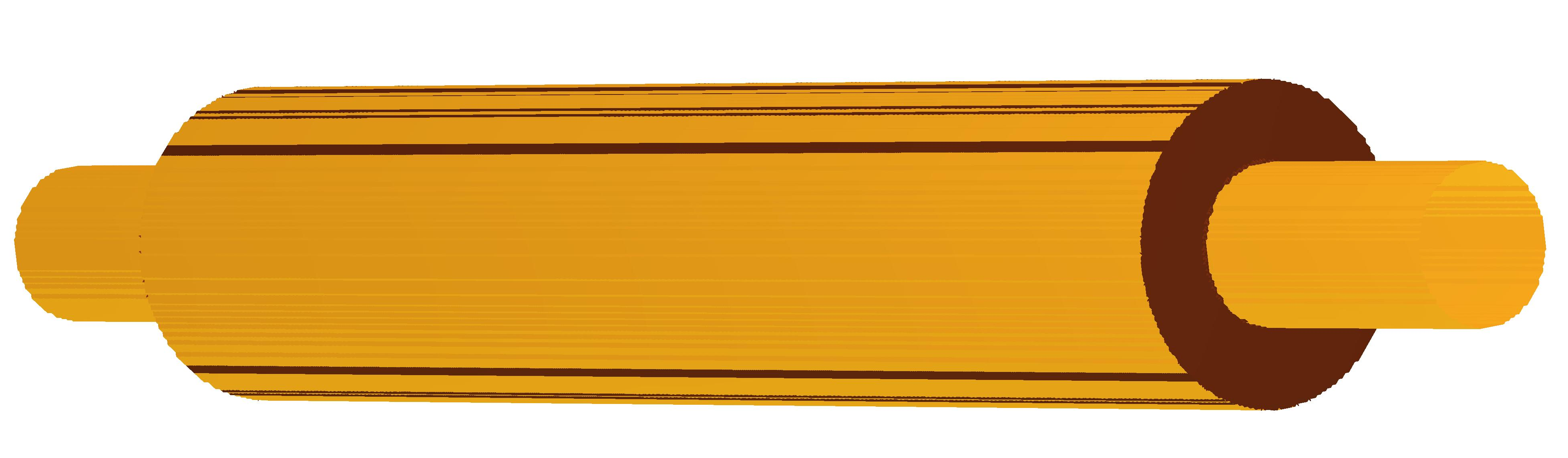
Only recently a possibility to carry out simulations with resistive walls (RW), implementing the impedance boundary conditions, was made available in GdfidL. So it has been decided to perform a numerical test comparing the simulation results with known analytical formulas. For this purpose we calculated both the longitudinal and the transverse loss factors (the latter known also as kick factor) of a Gaussian bunch passing inside a round beam pipe having an azimuthally symmetric thick resistive insert. The insert was enough long in order to be able to neglect the contribution of the insert ends, as shown in Fig. 1.
In this case the loss factors can be found analytically:
| (1) |
for the longitudinal one and
| (2) |
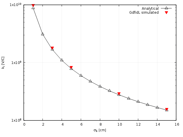
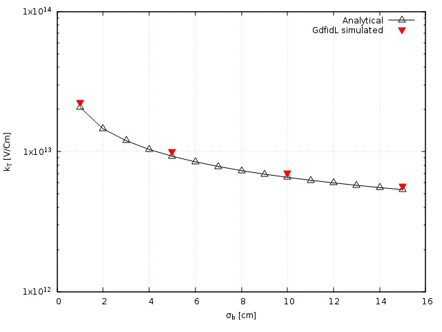
for the transverse one, where m/s is the speed of light, is the length of the pipe, is the electrical resistivity, the bunch length and the Euler gamma function. Figure 2 shows a comparison between the analytical formulas and the numerical data. As it is seen the agreement is quite satisfactory.
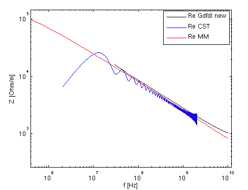
However, the loss factors are somewhat “averaged” values characterizing the beam impedance. In order to check the impedance frequency behavior the RW impedance of the insert has been calculated using the semi-analytical mode-matching method (MMM) [6]. In turn, numerically the impedance till rather low frequencies has been obtained by performing a Fourier transform of a long wake behind a long bunch obtained by Gdfidl, and also by CST for comparison. As it is seen in Fig. 3 also the impedance frequency behavior is reproduced well by GdfidL.
3 Ferrite Material Simulation Test
In order to damp parasitic higher order modes (HOMs) in the new collimators with embedded BPM pickup buttons, special blocks made of the TT2-111R lossy ferrite material are used. For this reason we have carried out a comprehensive numerical study to test the ability of GdfidL to reproduce frequency dependent properties of the lossy ferrite in calculations of wake fields, impedances and scattering matrix parameters [7].
For this purpose, we have a) simulated a typical coaxial-probe measurement of the ferrite scattering parameter ; b) compared the computation results of CST, GdfidL and Mode Matching Techniques by calculating impedances of an azimuthally symmetric pill-box cavity filled with the TT2-111R ferrite in the toroidal region; c) benchmarked GdfidL simulations against analytical Tsutsui model for a rectangular kicker with ferrite insert [8, 9] and CST simulations for the same device.
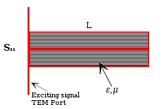
All the comparative studies have confirmed a good agreement between the results obtained by GdfidL and the results provided by other numerical codes, by available analytical formulas and by the mode matching semi-analytical approach. As an example, Fig. 4 shows a simplified sketch of a set-up for the ferrite material properties measurements: just a coaxial line filled with a ferrite material under test. For such a simple structure the reflection coefficient is easily measured and can be found analytically as in Eq. (3).
| (3) |
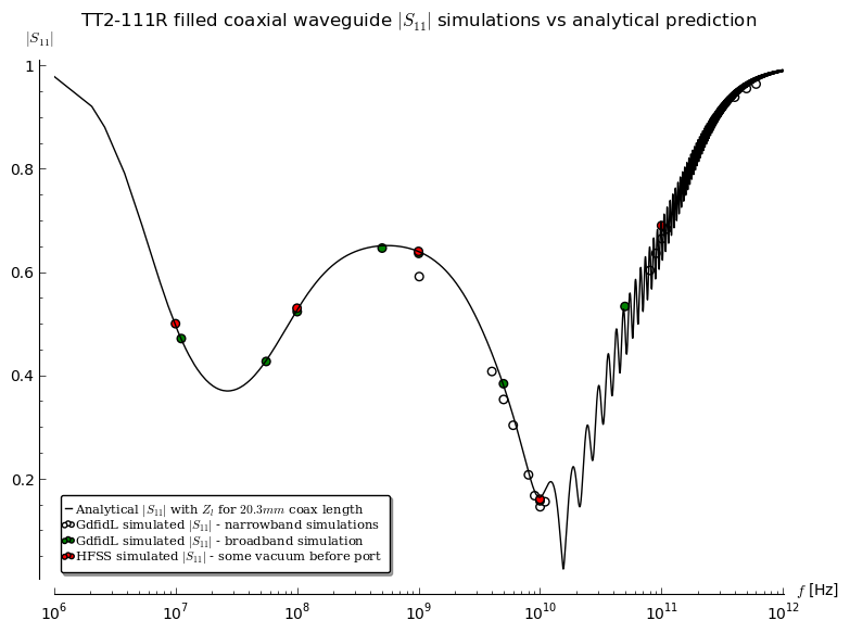
with and . Figure 5 shows the coefficient calculated for the TT2-111R material in a very wide frequency range, from to Hz. As it is seen, despite the complicated frequency dependence the agreement between GdfidL, HFSS and the analytical formula is remarkable.
4 Impedance of LHC Run I TCS/TCT Collimators
In the 2012 LHC impedance model, collimators played the major role () over a wide frequency range, both for real and imaginary parts, but the model was essentially based on the resistive wall impedance of collimators, the resistive wall impedance of beam screens and warm vacuum pipe and a broad-band model including pumping holes, BPMs, bellows, vacuum valves and other beam instruments. The geometric impedance of collimators was approximated only by that of a round circular taper [10].
However, several measurements were performed in 2012 of the total single bunch tune shifts vs. intensity, both at injection and at 4 TeV, the results coming out to be higher than predicted ones with numerical simulations by a factor of at top energy and of at injection [11]. This fact led to the need for an LHC impedance model refining which, first of all, required a careful collimator geometric impedance calculation. For this purpose, we carried out numerical calculations of the geometric impedance of the LHC Run I TCS/TCT collimator, whose design is shown in Fig. 6, and evaluated its contribution to the overall LHC impedance budget.
In order to verify whether the geometric collimator impedance could give a noticeable contribution to the betatron tune shifts, we suggested to compare transverse kick factors due to the resistive wall impedance and the geometric one, showing that the tune shifts are directly proportional to the kick factors [12].
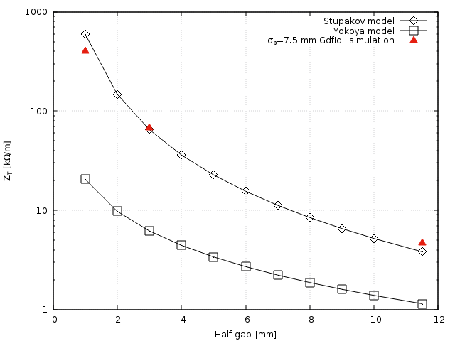
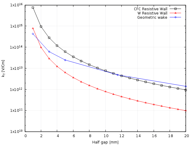
In Fig. 7 and Fig. 8 the main results about the transverse broad-band impedance and kick factors are reported, showing that the geometric impedance is better approximated by a flat taper model than by a round taper one and that the geometric contribution is not negligible with respect to the resistive wall one. In particular, for CFC made collimator, the geometrical kick starts to be comparable to resistive wall one at about 8 mm half gap. In turn, for W made collimators, the geometrical kick dominates almost for all the collimator gaps.
The study contributed to the refinement of the LHC impedance model. It has also been shown that the geometrical collimator impedance accounts for approximately of the total LHC impedance budget, at frequencies close to 1 GHz.
5 Impedance of LHC Run II TCS/TCT Collimators
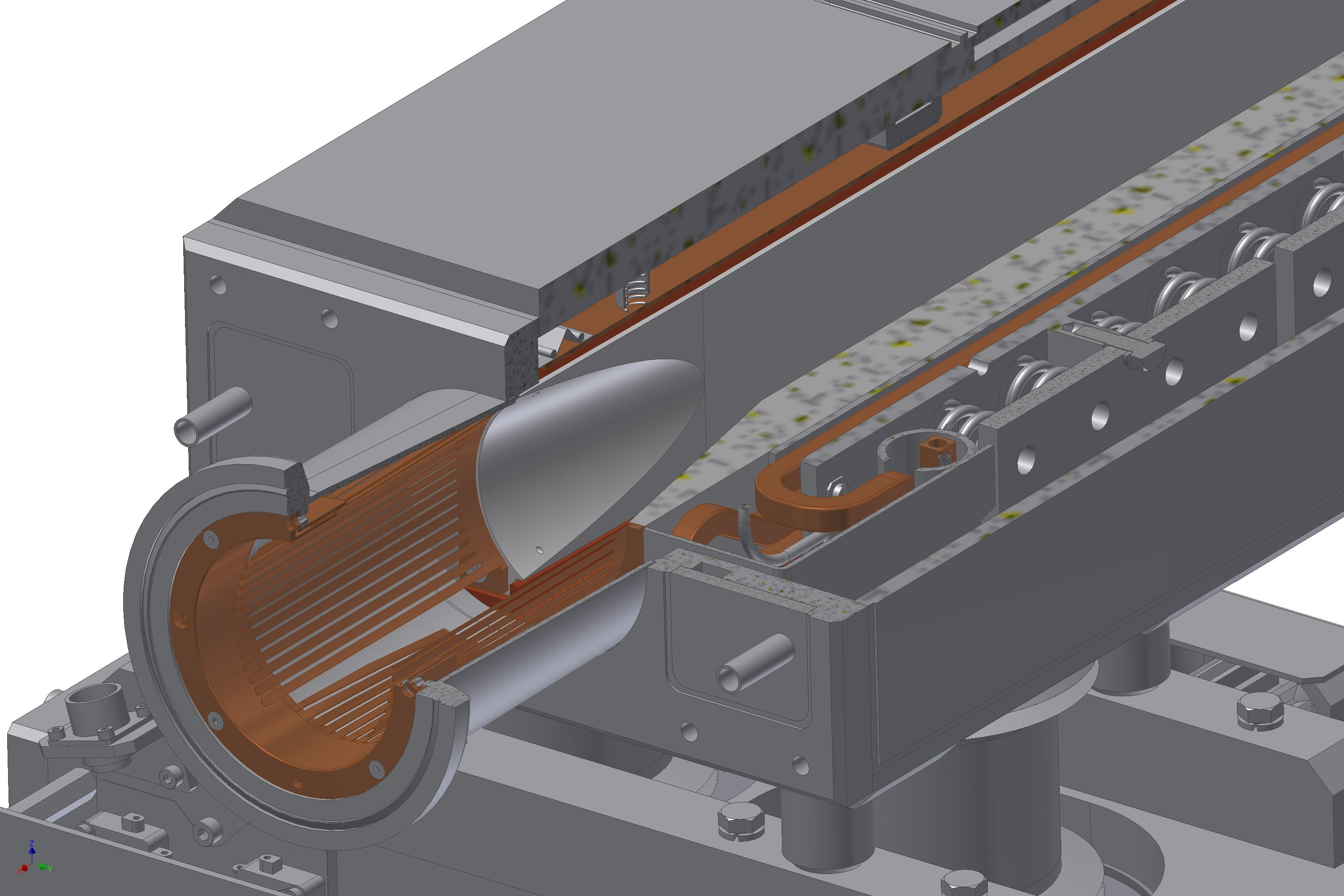
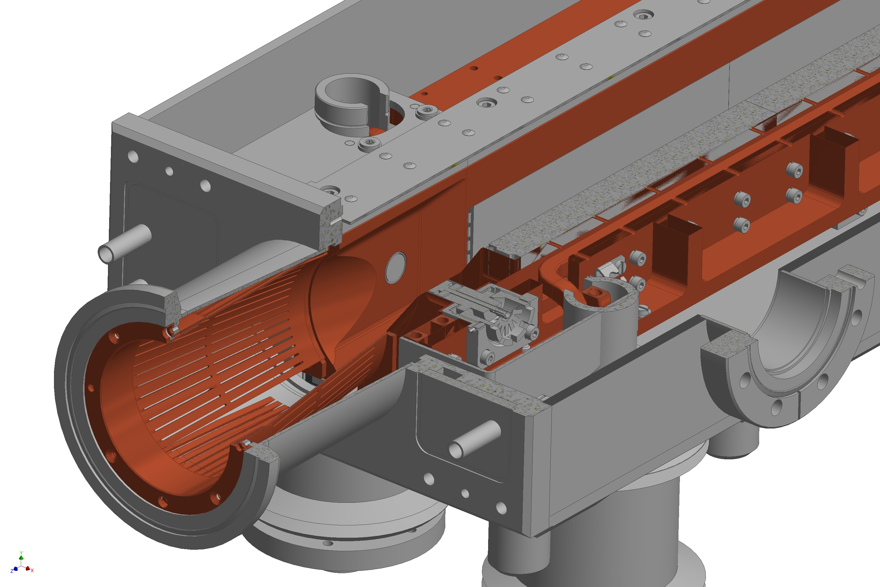
During the last LHC Long Shutdown I (LSI), 2 TCS CFC and 16 TCT Tungsten (W) collimators were replaced by new devices with embedded BPM pickup buttons, whose design is shown in Fig. 9.
RF fingers were removed from the previous LHC Run I TCS/TCT design and HOMs damping was entrusted to the TT2-111R ferrite blocks. By means of GdfidL broad band impedance simulations of the new collimators’ real structure, we gained the results for the kick factors in Tab. 1, showing that an increase of about is expected for the transverse effective impedance, with respect to LHC RUN I type collimator’s design.
| w/ BPM cavity | w/o BPM cavity | |
|---|---|---|
| Half gaps (mm) | ||
| 1 | ||
| 3 | ||
| 5 |
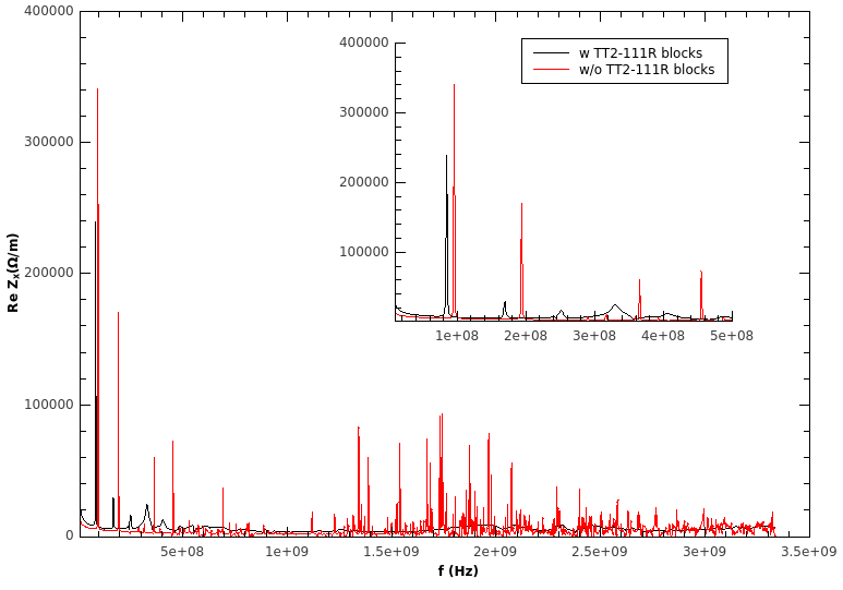
In order to study the impedance behaviour of the new collimators and the effect of the ferrite blocks on HOMs, we performed detailed GdfidL wake fields simulations of the whole real structures. We set into GdfidL input file the finite conductivity of W and the frequency-dependent permeability of TT2-111R. As a first result, an overall impedance damping feature was shown to be proper of the structure with resistive W jaws plus ferrite blocks at all frequencies [13], as clearly visible from the plot in Fig. 10. There, the red curve represents the collimator simulated as a whole Perfect Electrical Conductor (PEC), without any resistive and dispersive material, while the black one represents the real collimator with W jaws and ferrite blocks. The effect of ferrite results also in the shift of HOMs characteristic frequencies toward lower frequencies. As an example, the first HOM frequency shifts from MHz to MHz, at exactly the same frequency measured experimentally at CERN with loop technique [14]. It is clear that the computed impedance spectrum resolved very well the low frequency HOMs, whose characteristic frequencies are in excellent agreement with those found experimentally.
6 Conclusions
Calculations of wake fields and beam coupling impedance have been performed for the LHC TCS/TCT collimators, by means of GdfidL electromagnetic code. We performed, for the first time in the field of impedance computations, a complete and detailed simulation campaign of collimators’ real structures, including the properties of real and lossy dissipative materials.
For LHC Run I collimators, the comparison of the transverse kick factors calculated for five different jaws’ half gaps, has shown that the geometric impedance contribution is not negligible with respect to the resistive wall one. The study has contributed to the refinement of the LHC impedance model, as a result of the geometrical collimator impedance accounting for approximately of the total LHC impedance budget, at frequencies close to 1 GHz.
The performed numerical tests have confirmed that GdfidL reproduces very well the properties of the lossy dispersive materials. The simulation test results for the resistive walls and the lossy ferrites are in a good agreement with available analytical formulae and the results of other numerical codes and semi-analytical models. The tests have made us confident in the results of our impedance studies carried out for the real structures of the new Run II TCS/TCT collimators with incorporated BPMs. Several important results have been obtained conducting these studies. First, we found that there are no dangerous longitudinal higher order modes till about 1.2 GHz. This is important for the heating reduction of the collimators in the multibunch regime (for the nominal LHC bunches 7.5 long). Second, the TT2-111R ferrite resulted to be very effective in damping both longitudinal and transverse parasitic modes for frequencies above 500 MHz. However, the modes at lower frequencies are less damped, residual transverse HOMs at frequencies around 100 MHz and 200 MHz with non-negligible shunt impedances still existing. The calculated frequencies of the modes are in remarkable agreement with the loop measurements. The shunt impedances of the modes obtained numerically agrees within a factor of 2 with the experimental data of the wire measurements performed at CERN. Finally, the broad-band transverse impedance of the new LHC Run II double taper collimators are evaluated to be approximately by 20% higher with respect to that of the LHC Run I TCS/TCT collimators.
7 Acknowledgments
We are grateful to W. Bruns for his invaluable support.
We would like to thank also the CERN EN-MME and BE-ABP departments, for the providing of the collimators’ CAD designs and S. Tomassini, of INFN-LNF, for his accurate handling and adjusting the CAD designs to serve as inputs for GdfidL simulations. In particular special thanks are addressed to the E. Metral, on behalf of the whole CERN LHC impedance group, for the support and profitable discussions, to N. Biancacci for the MMM simulations’ data and, together with F. Caspers, J. Kuczerowski, A. Mostacci and B.Salvant for the information on the collimators’ impedance measurements side.
References
- [1] R.W. Assman et al. Requirements for the LHC collimation system. Proceedings of the 8th European Particle Accelerator Conference, pages 197–199, 2002.
- [2] R.W. Assman et al. An improved collimation system for the LHC. Proceedings of the 9th European Particle Accelerator Conference, pages 536–538, 2004.
- [3] E. Metral et al. Transverse Impedance of LHC Collimators. Proceedings of Particle Accelerator Conference PAC07, pages 2003–2005, 2007. CERN-LHC-PROJECT-REPORT-1015.
- [4] The HL-LHC collaboration. HL-LHC Preliminary Design Report Deliverable: D1.5. Technical report, 2014. CERN-ACC-2014-0300.
- [5] W. Bruns. GdfidL web page. http://www.gdfidl.de.
- [6] N. Biancacci, V. G. Vaccaro, E. Métral, B. Salvant, M. Migliorati, and L. Palumbo. Impedance studies of 2d azimuthally symmetric devices of finite length. Phys. Rev. ST Accel. Beams, 17:021001, Feb 2014.
- [7] O. Frasciello et al. Wake fields and impedances calculations with GdfidL, MMM and CST for benchmarking purposes, 2014. Contributed talk at BE-ABP Impedance meeting, February 2nd, CERN, Geneva, Switzerland.
- [8] H. Tsutsui et al. Transverse Coupling Impedance of a Simplified Ferrite Licker Magnet Model. Technical report, 2000. LHC-PROJECT-NOTE-234.
- [9] H. Tsutsui. Some Simplified Models of Ferrite Kicker Magnet for Calculations of Longitudinal Coupling Impedance. Technical report, 2000. CERN-SL-2000-004 AP.
- [10] N. Mounet. The LHC Transverse Coupled-Bunch Instability. PhD thesis, Ecole Polytechnique, Lausanne, Mar 2012.
- [11] N. Mounet et al. Beam stability with separated beams at 6.5 tev. In LHC Beam Operation Workshop Evian 17-20 December 2012, 2012.
- [12] O. Frasciello et al. Geometric beam coupling impedance of LHC secondary collimators. In Proceedings of IPAC 2014.
- [13] O. Frasciello et al. Present status and future plans of LHC collimators wake fields and impedance simulations, 2015. Contributed talk at BE-ABP Impedance meeting, March 23rd, CERN, Geneva, Switzerland.
- [14] N. Biancacci et al. Impedance bench measurements on TCTP collimator with ferrite, 2014. Contributed talk at BE-ABP Impedance meeting, August 8th, CERN, Geneva, Switzerland.
- [15] N. Biancacci et al. Impedance bench measurements on TCTP and SLAC collimators, 2014. Contributed talk at BE-ABP Impedance meeting, April 14th, CERN, Geneva, Switzerland.
- [16] O. Frasciello et al. Beam coupling impedance of the new LHC collimators, 2015. Contributed talk at 101st National Congress of the Italian Physical Society (SIF), September 24th, Rome, Italy.