DPF2015-350
Performance of Scintillator Counters with Silicon Photomultiplier Readout
Mu2e Collaboration Cosmic Ray Veto Group
The performance of scintillator counters with embedded wavelength-shifting fibers has been measured in the Fermilab Meson Test Beam Facility using protons. The counters were extruded with a titanium dioxide surface coating and two channels for fibers at the Fermilab NICADD facility. Each fiber end is read out by a silicon photomultiplier. The signals were amplified and digitized by a custom-made front-end electronics board. Combinations of and extrusion profiles with and diameter fibers were tested. The design is intended for the cosmic-ray veto detector for the Mu2e experiment at Fermilab. The light yield as a function of the transverse and longitudinal position of the beam will be given.
PRESENTED AT
DPF 2015
The Meeting of the American Physical Society
Division of Particles and Fields
Ann Arbor, Michigan, August 4–8, 2015
1 Introduction
The Mu2e experiment at Fermilab intends to make the most sensitive measurement of the neutrinoless, coherent conversion of muons into electrons in the field of a nucleus [1]:
This process is an example of charged lepton flavor violation, and its detection would be unambiguous evidence for physics beyond the Standard Model.
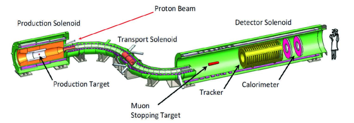
The layout of the Mu2e experiment is shown in Figure 1 [1]. The high-intensity pulsed proton beam impacting the production target produces muons among other particles. The muons propagate through the transport solenoid and roughly half are captured in the stopping target. If a muon is converted into an electron via the conversion process, a electron would be ejected from the stopping target, which should be detected by the tracker and calorimeter.
One major background source for the Mu2e experiment is cosmic ray-induced muons faking signal electrons by interacting with the detector materials [1]. Simulations show such background events occur at a rate of approximately one per day. For Mu2e to be able to reach its sensitivity goal, this background must be suppressed to 0.1 event over the entire 3-year lifetime of the experiment [1]. In order to combat this background, Mu2e relies on a cosmic ray veto (CRV) system.
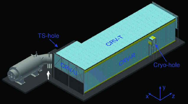
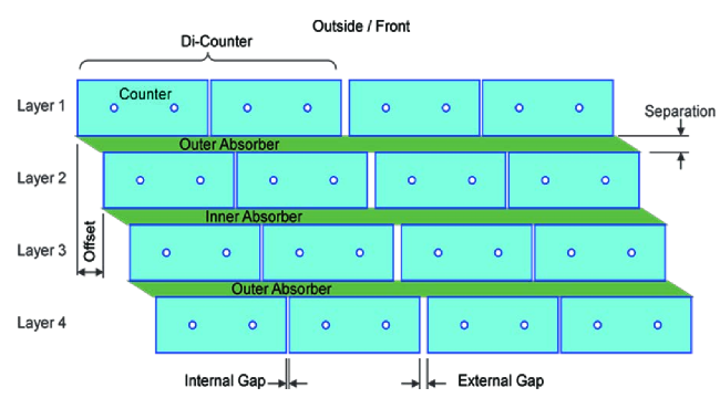
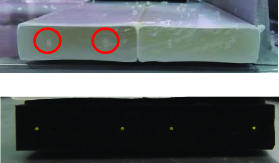
Figure 2 shows a schematic view of the Mu2e CRV detector [1]. The CRV covers the majority of the detector solenoid and about half of the transport solenoid shown in Figure 1 [1]. Simulations have shown that the vetoing efficiency of the CRV has to be at least and must withstand an intense radiation environment. Each side of the CRV consists of four staggered layers of scintillator counters (Figure † ‣ 3). Each scintillator counter contains two embedded wavelength shifting fibers.
The scintillator counters were tested at Fermilab in a proton beam [2]. The goal of the test was to measure the lateral and longitudinal response of the scintillator counter at different beam angles of incidence with 50 and 60-mm wide counters containing 1.4 and 1.8-mm diameter fibers.
2 Test Beam Setup
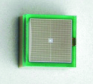
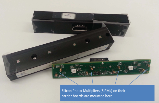
Figure 4 shows a photograph of the test beam setup. The scintillator counters were mounted on the test stand with the coordinate system shown in Figure 4. The 120 GeV protons are minimum ionizing, so they deposit a similar energy as minimum-ionizing muons. When a charged particle traverses the counter and deposits energy in the scintillator, light is produced which is captured by the wavelength-shifting fibers shown in Figure 5. The light is retransmitted to the ends of the counter where it is detected and amplified by Silicon Photo-Multipliers (SiPMs) shown in Figure 6. The SiPMs are mounted on small carrier boards that sit in wells which allow them to be pushed up against the fibers. A counter motherboard (CMB) as shown in Figure 7 with spring-loaded pins makes electrical contact with the SiPM carrier boards. Signals from up to 16 counter motherboards are sent to a front-end board by HDMI cables where they are amplified and digitized.
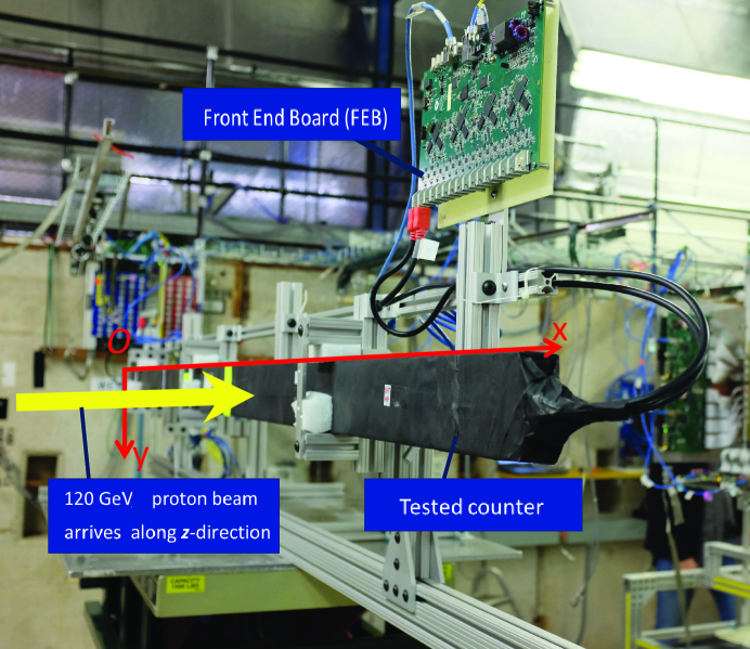
The counters are mounted on a rotatable support fixture on a table capable of translational motion, which allows us to place the proton beam at different positions on the counter and to vary incident angles. The change in incident angle changes the path length of the protons through the scintillator and therefore changes the light yield. A coincidence of beam scintillator counters read out by photomultiplier tubes is used to provide a trigger. Upon receipt of a trigger signal, the SiPMs were read out for with their signals digitized every . Four multiwire proportional chambers (MWPC), two upstream and two downstream of the CRV counters, provide tracking information [3], which allow us to reconstruct the proton trajectory to within at the counters.
3 Data Analysis
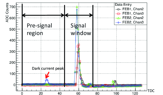
Figure 8 shows a typical event with all four channels on an extrusion. The pulses before the signal window are dark current peaks, which are used for calibration.
3.1 Calibration
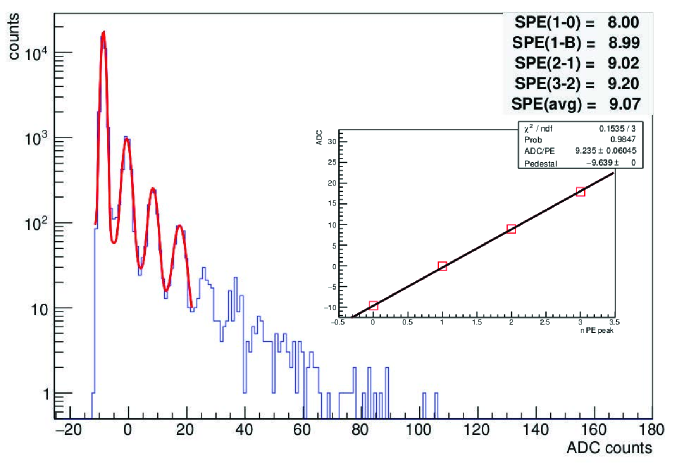
Since the SiPMs produce resolvable single pixel peaks, a calibration can be carried out to convert ADC units to the number of pixels. The distribution of the dark current peaks allows such a conversion. As shown in Figure 9, by fitting a function to the distribution, the positions of the peaks can be extracted and the average ADC per pixel fired can be calculated. The number of pixels fired is proportional to the number of incident photons with crosstalk. To find the photoelectron yield the crosstalk needs to be determined as discussed later.
3.2 Transverse and Longitudinal Response
After calibration the number of pixels fired in the SiPM for each event can be calculated. Then the transverse and longitudinal response of the extrusion can be studied.
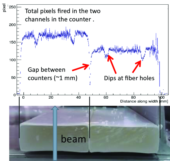
Figure 10 shows the transverse response with the beam incident at . The total number of pixels fired in the two channels on the end of the extrusion is plotted. From the figure it can be observed that the number of fired pixels is relatively constant across the width of the counter. The edges of the counter are well defined. The signal size does not fall below 50% until the beam incident position reaches about from the edges. The gap between the two extrusions is clearly evident. It has an effective width of about . Dips of 20% to 25% in the signal are also present at the locations where the fiber holes are. Such dips are expected and arise due to the reduced path length in the scintillator when the proton passes through one of the fiber holes. The difference between the total number of fired pixels in the two counters is very likely due to the different crosstalk levels between the SiPMs, which will be discussed in the following section.
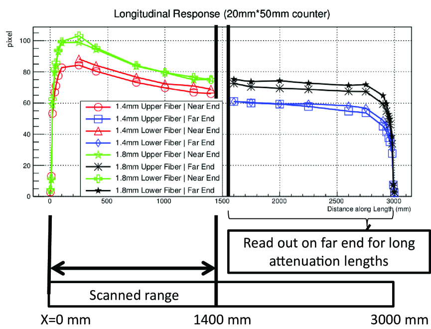
Figure 11 shows the longitudinal response of the extrusions with the beam centered between two fibers. Due to the limitation of the test facility, a full-length scan was impossible; instead, half the length of the extrusion was scanned (). In Figure 11 points greater than come from SiPM at the far () end. Each data point corresponds to the average number of fired pixels of a single SiPM. The nice aggreement between the data taken from different channels indicates a consistency among the SiPMs. Simulations show the response of the counter along its length is consistent with the fiber attenuation length. Figure 11 also shows that the light output of the 1.4-mm and 1.8-mm diameter fibers has a difference of about 15%.‡‡‡Recent bench-test measurements using sources and cosmic ray muons show a larger increase of almost 40%, which is expected. Misalignment at the the fiber and the SiPMs is presumed to be the reason for the lower increase observed here.
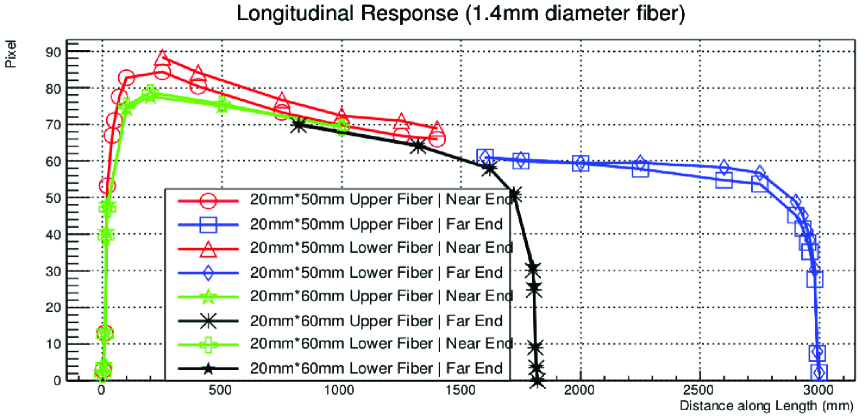
Figure 12 shows the small performance difference between the 50-mm and 60-mm wide extrusions.
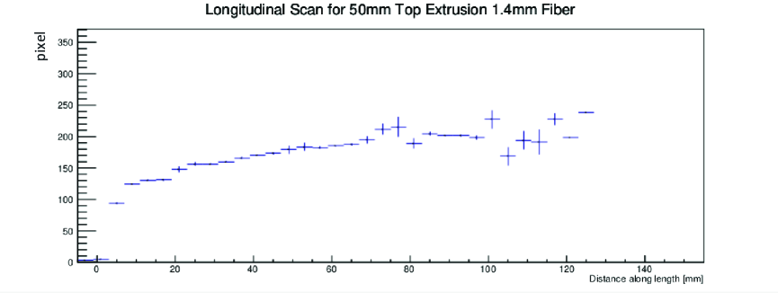
Figure 13 provides a close-up view of the longitudinal response at small x values.A fall-off is present in the longitudinal response towards the ends, which is thought to be caused by photons being absorbed by the dark-colored fiber guide bars. Detailed Monte Carlo studies are underway.
3.3 Photoelectron Yield and Cross Talk
We have been careful to only report the pixel yield of the devices. To obtain the photoelectron yield from the pixel yield, the effect of cross talk needs to be considered. By crosstalk we mean pixels that induce neighboring pixels to fire, which inflates the pixel count. Hamamatsu, the SiPM provider, reports a 40% cross talk at their operating bias, where their definition is the ratio of the 2-pixel peak to the 1-pixel peak in the noise response. The investigation of the cross talk at the biases used in the test beam is in progress using several different techniques. The results are not yet mature enough to be discussed here. However, it should be pointed out that when using a preliminary crosstalk correction, for example, Figure 10 shows a much more uniform response across the two counters. We find using these preliminary results that photoelectron yields are roughly a factor of two less than pixel yield. On a side note, the SiPM model tested is no longer being produced. A different device with much lower crosstalk will be tested in a test-beam run early in 2016.
4 Conclusions
The Mu2e cosmic ray veto (CRV) system is an essential component of the Mu2e experiment. The test beam measurements were carried out to understand the performance of the scintillator counters used in the Mu2e CRV system to ensure that they satisfy the design requirements.
The test results demonstrate a generally uniform response of the counter along its width with a sharp drop-off away from the edges. Between the two counters of a di-counter an effective gap of width is present. Fiber holes in the counters have a small effect on the signal level when a particle passes through the hole. The response of the counter along its length is consistent with the fiber attenuation length.
References
- [1] L. Bartoszek et al, “Mu2e Technical Design Report (TDR)”, arXiv:1501.05241.
- [2] “Fermilab Test Beam Facility”, ftbf.fnal.gov/beam-overview/.
-
[3]
“Presentation on Fenker Chambers”,
ppd.fnal.gov/ftbf/instrumentation/MWPC.html.