Rotation of a melting ice at the surface of a pool
Abstract
Large circular ice blocks up to 80 m of diameter have been observed on frozen river around the world. This rare event has been reported in a publication in 1993. This fascinating self-fashioned object slowly rotates at about 1o per second. In this paper, we report a model experiment consisting in a 85 mm of diameter ice disc at the surface of a thermalised pool. The rotation speed has been found to increase with the bath temperature. Using particle image velocimetry technique, we evidence the presence of a vortex below the ice block. This vortex results from the descending flow of high density water at 4oC. The vorticity of the vortex induces the rotation of the ice block. This mechanism is generic of any vertical flow that generates a vortex which induces the rotation of a floating object.
pacs:
64.70.dj,47.32.C-,47.55.pbI Introduction
Around the world large floating ice blocks have been observed on frozen rivers. This pretty rare phenomenon can be observed during winter news broadcast as the discs surprisingly rotate. In a paper of 1993, Nordell et al reported several events of rotating ice discs weather . The Table I presents the diameters , the rotating speed expressed in degrees per second for different observations (place, date and references are indicated). The last line concerns the observation along the present work. The size of the discs has been observed to spread over 2 orders of magnitudes from 1 m to 100 m. On the other hand, the rotation speeds do not seem to depend on the size of the disc. One notes that are of the order of 0.90.4 deg/s. The mechanism of the disc formation is still to be discovered in detail. Nowadays, two hypothesis are confronted: either the disc is thought to be created by the aggregation of frazil ice in a vortex generated by the river or an ice block is formed before being rounded weather . In the present paper, we study ice discs released at the surface of a pool of water maintained at a given temperature. We discover that the disc starts rotating spontaneously. We found that, while melting, the ice disc generates a vortex under its immersed surface. This vortex is sufficient to make the ice disc rotate.
| (m) | (deg/s) | place | year | ref |
|---|---|---|---|---|
| 2 | 0.57 | Rancho Nuevo Creek, USA | 1983 | eos |
| 3 | 1.4 | River Otter, UK | 2009 | daily |
| 8 | 1.4 | Mianus River, USA | 1895 | sa |
| 49 | 0.66 | Pite River, Noway | 1987 | weather |
| 55 | 1.3 | Nidelva River, Norway | 1971 | hblanche |
| 79.8 | 0.54 | Pite River, Norway | 1994 | weather |
| 81 | 0.46 | Pite River, Norway | 1994 | weather |
| 0.085 | 3 (at 20oC) | this work |
II Experimental set-up
The water pool consisted in a large stainless steel circular vessel (300 mm of diameter and 150 mm of depth). The water pool is plunged in an intermediate bath which temperature is regulated by flowing thermalised water through a copper serpentine (see Fig.1). The thermalized water comes from a flow thermostat (Julabo F12-ED). Finally, two caps were placed at the surface of the intermediate bath (where a pump mixed the liquid for homogenezation purpose) and over the whole experiment in order to avoid any perturbation by the air environment.
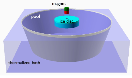
The ice discs were produced out of circular Petri dish (85 mm of diameter and 14 mm of height ). The Petri dish were embedded in polystyrene so as the bottom part of the petri dish is not covered. Then the polystyrene frame containing petri dish filled with water are placed in a freezer (-32oC). As the water starts freezing by the bottom of the Petri dish, bubbles and dust are pushed towards the surface of the water. Bubble free ice discs were consequently obtained.
A dark ellipse (about 50 mm long and 20 mm large) was put on the floating ice disc. By image analysis, the position of the center of the ellipse and its angular position were measured which allows to determine the motion of the ice disc during the melting. The images were captured from a webcam and treated in real-time using a Python program and the OpenCV library.
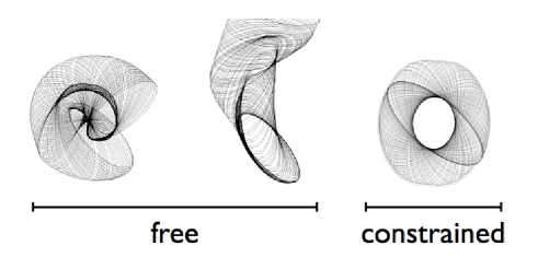
While melting, one observes that the ice discs move at the surface of the bath. Sometimes they were rotating similarly to the spinning ice discs observed in Rivers. Sometimes they were rotating and translating at the surface of the bath. The ellipse contours have been superimposed to deduce the motion of the discs (1 second separates each successive ellipse). Three typical trajectories are presented in Fig. 2, from left to right: a rotation, a combination of two rotations and the combination of a translation and a rotation. In order to increase the reproducibility, we suppressed the translational degrees of freedom by constraining the ice disc along a vertical axis crossing the disc at its center. A small nickel bead (2 mm of diameter) was embedded at the bottom center of the ice discs before freezing. A fixed magnet was placed above the surface of the bath and attracted the nickel bead and consequently the ice disc. Note that the nickel was chosen because (i) the nickel does not oxidise and (ii) the nickel is ferromagnetic with a small remanent field at 273 K. Indeed, if a magnet was placed in the ice disc instead of the Ni-bead, a torque on the disc may result in the perturbation of the disc motion.
III Observations and results
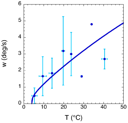
In Fig.3, the rotation speed [o/s] is plotted as a function of the temperature of the pool. We observe that, even constrained about a vertical axis, the data is rather spread. The data were binned by 5oC boxes and averaged (big bullets in Fig.3). One observes a clear increase of the rotation speed with the temperature of the pool. The rotation starts to be efficient for a temperature larger than 5oC. This fact indicates that the origin of the rotation is related to the so-called anomaly of the water density behavior with the temperature. Indeed, the density of the water is maximal at a temperature of 4oC.
In order to visualize the motion of the fluid below the ice disc, we colorised the water used to make the discs. This simple experiment allows us to observe the formation of a vortex below the ice disc. The radius of the vortex is typically half that of the disc.
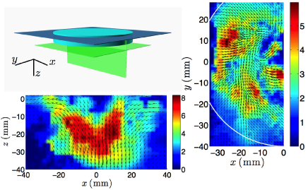
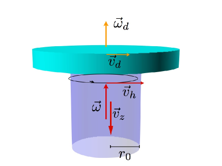
Quantitative results were obtained by using Particule Image Velocimetry (PIV) technique from DantecDynamics. Fluorescent particles were inserted in the liquid of the bath contained in a transparent tank. For this part, the bath temperature was 20oC. A green LASER of excitation was used and a Phantom camera recorded the motion of the particules. Again, the ice disc was constrained to rotate about one vertical axis defined by using a magnet. The PIV investigations were performed along two perpendicular planes: (i) one plane was taken parallel to the bath surface about 5 mm below the bottom surface of the ice disc and (ii) one plane was take perpendicular to the bath surface intercepting the axis of rotation of the ice disc (see Fig. 4).
In Fig. 4, the velocity fields are presented for both concerned planes (parallel and perpendicular ). First, concerning the vertical plane , we observe that the fluid moves towards the center of the ice disc located around mm. The maximum speed observed at 1 mm below the bottom of the ice disc ( mm) is about 10 mm/s downwards. The analysis of the horizontal plane also indicates maximum speed of the same order of magnitude. Moreover, a rotation of the flow is observed below the ice disc; in the present case at mm and 10 mm. Regarding these observations, we conclude that a downwards flow is generated below the ice which creates a vortex. The latter induces the rotation of the disc. This is supported by the fact that when the level of the water in the pool is low (3 cm), the ice disc does not rotate.
The proposed mechanism is the following. The ice disc melts and decreases locally the water temperature close to the bottom side of the disc. Eventually, the water reaches locally the temperature of 4oC. At this temperature the density of the water is the highest and the fluid element plunges in the pool. This process is the symmetrical situation to the natural convection. Indeed, this is also supported by the evaluation of the Rayleigh number
where , , and are the thermal expansion (88.10-6/K), the thermal diffusivity (1.5.10-7 m2/s), the kinetic viscosity (10-3 Pa s) and the density (1000 kg/m3) of the water respectively, the gravity acceleration and () the characteristic length of the system. One finds . The plume is similar to plume observed in soap films adam1 ; adam2 Consequently, regarding the PIV measurement, a model of thermal plume can be applied. In Ref.book , the buoyancy flow is defined as
| (1) |
where and are respectively the density of water and the heat capacity at constant pressure and is the heat flux. Taking into account the heat, the mass and the momentum budget on thin slide of plume, Cushman-Roisin finds an expression for the velocity of the fluid at the center of the plume
| (2) |
where the vertical position being the location of the ice disc bottom face.
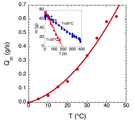
The thermal flux can be evaluated by determining the flux of mass of the ice disc if we consider that the heat is used to change the ice into water plus the heat necessary to heat the ice from -30oC to 0oC,
| (3) |
where and are the latent heat of the fusion and the specific heat of ice respectively. The mass of the ice disc as been recorded during the melting. The procedure consisted in weighting the ice disc as a function of time by briefly pulling the disc out of the pool using a string attached to a force sensor. In the inset of Fig. 5, the mass of the ice disc is presented as a function of time when the pool is at 20oC (red triangles) and at 35 oC (blue circles). The evolutions of were fitted by a linear trend for different temperatures of the pool. The angular coefficients are reported as a function of the pool temperature in Fig. 5. In the considered range of temperature, one finds that . With the assumption that the vertical speed is due to the water anomaly we found that
| (4) |
taking (in the range 4C) tool , =1000 kg/m3, =4202 J/kg/K, =2060 J/kg/K, =20 oC (the difference of temperature between the ice/water transition and the pool) and cm as in the PIV measurement, one finds mm/s in pretty good agreement with the PIV measurements even the effect of the thermal gradient is not taken into account.
The plume causes the vertical flow which generates a vortex. The relation between the vertical flow and the vortex velocity is rather complex (see for example lewellen ). In the present case, the vertical flow is driven by natural convection. Our approach is phenomenological as we observed that the vertical speed of the plume is of the same order of magnitude than the vortex. Moreover, we observe that the vortex radius is half the radius of the ice disc. The vortex angular momentum entrains the rotation of the disc . The rotation of the disc is postulated to be a viscous entrainment on a boundary layer of a thickness . As a consequence, the driving force is given by
| (5) |
with is the viscosity of the water. On the other hand, the friction of the disc with the pool limits the rotation. This friction occurs along the lateral surface of the disc and on the remaining surface on the bottom side of the disc. Taking the same argument as for the entrainment, the friction force is due to viscosity on a layer of thickness reads
| (6) |
where is the thickness of the ice disc. As the rotation speed of the disc is constant, the forces balance and we obtain a relation for the coupling
| (7) |
Applied to the present case, one finds that with mm.
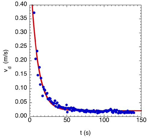
The layer thickness can be evaluated as following. Ice discs were spinned by hand. The rotation motion has been recorded and consequently, the linear speed were computed as a function of time. In Fig. 7, the tangential speed of the disc is reported as a function of time. The data were fitted by a decreasing exponential which provides the relaxation rate s-1. This behavior indicates that the tangential speed may remodelled by a differential equation where is the mass of the ice disc. The decrease of the speed comes from the friction of the disc (lateral surface and bottom side) with liquid. The calculation is similar to Eq.(6). The integral is performed from to instead of between and . One obtains
| (8) |
One can then determine the value of m.
Finally, we make the assumption that the horizontal speed responsible for the vortex and then for the rotation of the ice disc scales similarly to the vertical speed . In so doing, one finds that
| (9) |
The blue curve in Fig. 3 is the fit to the data using this scaling where is a free parameter and m. The agreement is fairly good as only the aspect ratio of the vortex has been left free. Note also that the viscosity of the water does not intervene in the final description of the rotation speed Eq.(8). Indeed, as the propulsion mechanism and the friction mechanism have the same physical origin, the role of the viscosity cancels.
IV Conclusion
The spontaneous rotation of an ice disc has been studied at the laboratory scale. The proposed mechanism is that the ice disc cooled the water of the pool. As the water reaches the temperature of 4oC, the water sinks generating a downwards plume and a subsequent downwards flow. This flow trigs a vortex that entrained the ice disc in rotation through a viscous process. This allows to understand why such a process cannot be observed in lakes because the water deep in the lake is at 4oC while the water in between the ice and the bottom is between 0 and 4oC. The thermal plume cannot born. In the rivers, the situation is different as the flow is sufficient to generate the rotation. Finally, one also understands why melting iceberg does not rotate as the melting results in diluting salted sea water. The density inversion cannot be triggered. This mechanism is generic. For example, a caramel disc has been attached to a floating circular boat. The melting of the caramel has generated the rotation of the boat.
Acknowledgements.
SD thanks F.R.S.-FNRS for financial support. This research has been funded by the Interuniversity Attraction Pole Programme (IAP 7/38 MicroMAST) initiated by the Belgian Science Policy Office and by ARC SUPERCOOL.References
- (1) B. Nordell and G. Westerstrom, Weather 52, 17 (1993).
- (2) E. Hvolboll, EOS 64, cover page (1983).
- (3) Spinning ice disc phenomenon seen in British river for first time, The Telegraph, Jan. 13th (2009).
- (4) J. M. Bates, Scientific American 72, 85 (1895).
- (5) T. Carstens, La Houille Blanche 7, 642 (1971).
- (6) N. Adami, S. Dorbolo, and H. Caps, Phys. Rev. E 84, 046316 (2011).
- (7) B. Martin and X. L. Wu, Phys. Rev. Lett. 80, 1892 (1998).
- (8) B. Cushman-Roisin, Environmental fluid mechanics (Thayer School of Engineering, Hanover, 2015).
- (9) Water-Thermal properties, The Engineering Toolbox.
- (10) W. S. Lewellen, J. Fluid Mech. 14, 420 (1962).