Capacitive displacement method to determine the longitudinal piezoelectric coefficients of single crystals, ceramics and thin films
Abstract
Recent developments in piezoelectric films have heightened the need for the reliable methods to correctly characterize their piezoelectric coefficients. Here, we demonstrate that capacitive displacement method can be used to determine longitudinal piezoelectric coefficients in both bulk and thin film of piezoelectric materials reliably and simply. Our technique allows accurate detection of elastic displacement at a level of 2 pm. This achievement is of great interest and significance for the development of piezoelectric integration technology in modern smart devices.
pacs:
77.65.-j,77.65.Bn,77.55.H-,81.70.-qPiezoelectrics convert mechanical energy into electric energy or vise versa, and show direct or converse effects.Curie ; Jaffe ; Lines ; Uchino In the direct effect, electric charge is produced at the surface of piezoelectric crystal in proportion to the applied stress. Conversely, as a suitably oriented electric field is applied, the crystal changes shape (strains) in proportion to the electric field. Such properties provide piezooelectrics a wide spectra of applications such as medical ultrasound imaging, fuel injecting in cars, ultra-precise positioning in optics or mechanics and sonar sensing in fish or submarine detection, and reserach on piezoelectric is still a hot topic of current material sciences.FuAPL2007 ; FuPRL2008 ; FuAPL2008 ; Rodel ; TazakiJPC2009 ; FuJPC2011 ; FuAPL2011 ; FuJPC2013 With the combination of modern thin film integration technology and nano-technology, piezolectrics can be used in nano-sensors, -actuators or -transducers in modern smart devices.Muralt1995 ; Muralt1997 ; Damjanovic ; DeVoe For these applications, understanding the piezoelectric properties of integrated thin film is of crucial importance.
Conventionally, to determine the piezoelectric coefficient of bulk materials, resonant anti-resonant dynamic method, -meter method based on the static direct effect, or interferometry method based on the static converse effect have been developed.Jaffe In principle, all these techniques can be used for the measurements on thin films.Pan ; Lefki ; Kanno ; Kholkin ; Christman ; Xu ; Durkan ; Kuffer ; FuJJAP ; Park Practically, one can find many difficulties in applying these techniques to measure the piezoelectric coefficient of thin films. In the resonant anti-resonant dynamic method, when the film thickness is on the order of 100 nm, the resonant and anti-resonant frequencies reach approximately 10 GHz, which makes pratical detection in a continuous frequency range extremely difficult. In addition to the dimension limitation, there is also an issue of substrate-constraint to be solved in the application of the resonant and anti-resonant method in thin films. Currently, to determine the piezoelectric coefficient of thin films, one usually probes the elastic deformation of the film with an electric field by the atomic force microscopy (AFM)Christman or interferometry.Pan ; Kholkin These two appoaches can provide a resolution of pm, however, AFM-tip-field electrostatic interactions Christman or the bending effects of substrate Kholkin may be a barrier for the reliable measurements of exact elastic deformation of the piezoelectric film. Therefore, reliable determination of the piezoelectric coefficient of thin films is still a challenging issue at present.
Here, we demonstrate that capacitive displacement method can be used to determine the longitudinal piezoelectric coefficients in both thin films and bulk materials reliably and simply. Our approach can correctly detect displacement as small as 2 pm and offers an opportunity of improved measurements of piezoelectric coefficient of thin films.
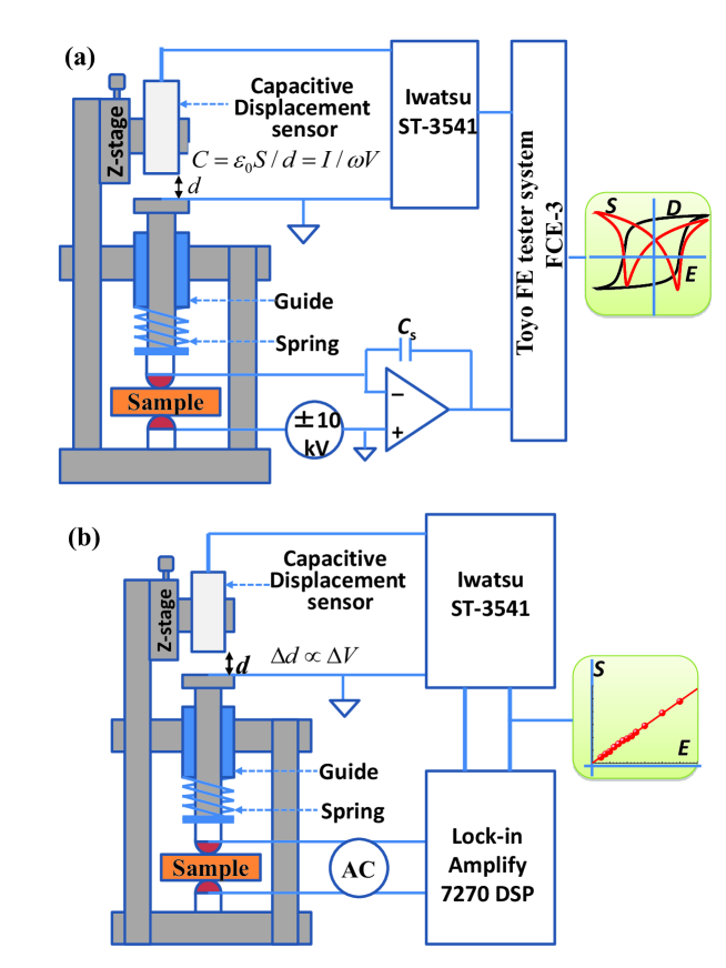
Figure 1 shows the schematic of our capacitive displacement method, in which the displacement is detected through detecting the change in air capacitance forming between the capacitive displacement sensor and the object to be measured. Here, we have
| (1) |
where is permittivity of vacuum, is the area of senor, is the distance between the sensor and the object to be measured, respectively. When voltage () with frequency is applied between the sensor and the object to be measured,
| (2) |
As can be seen from equation (2), when the current flowing through the sensor is maintained at a constant value, is proportional to the output voltage . Therefore, one can measure the displacement by measuring the output value of the capacitive sensor, which in our setup is performed by a commercial displacement meter Iwatsu 3541, providing a probing range of m with a resolution of approximately 1 nm. As shown in Fig. 1, the sample is held between two cylindrical electrodes that provide point contact between the sample and the cylindrical electrode, allowing free motion of the sample. When the electric field is applied to the piezoelectric sample, its longitudinal deformation is transfered to the bottom electrode of the air capacitor by a spring and a linear bush. Linear bush also provides a solid guide for the system. Using a Z-stage, one can adjust the air capacitance to set the output of the displacement meter to zero as the sample is in a resting state without an elastic deformation, which allows one to directly read the exact displacement using the displacement meter.
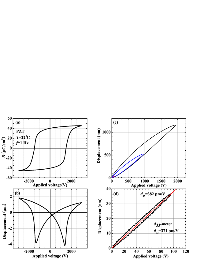
In the setup shown in Fig.1(a), the displacement meter is combined with a commercial ferroelectric tester (Toyo FE tester system FCE-3), which allows one to measure the D-E hysteresis loop and the strain loop simultaneously for a bipolar electric field. Reliable running of the system is confirmed by the results shown in Fig. 2, in which commercial Pb(Zr1-xTix)TiO3 (PZT) ceramics with a composition near the morphotropic phase boundary (MPB) was used. This ceramics sample shows a typical butterfly shape of strain loop for a bipolar field. For a unipolar field, it shows a large displacement of 1150 nm for an applied voltage of 1900 V. To examine whether the measured displacement is correct or not, we compare the result obtained at a lower voltage with that measured by a -meter ( Model ZJ-6B Quasi-Static Piezo /-meter made by Institute of Acoustics, Chinese Academy of Sciences.). For the applied voltage of 95.7 V, we have detected a displacement of 36.5 nm for the PZT ceramics sample. The ratio of displacement divided by the applied voltage is 382 pm/V, which provides an rough estimate of piezoelectric coefficient of the sample. This value is in good agreement with the value of 371 pm/V obtained by a -meter when considering that domain motion still has a small contribution to the total strain at this small applied voltage, which is evident from the small hysteresis of the strain curve. From these results, we can conclude that our capacitive displacement measurement system is highly reliable.
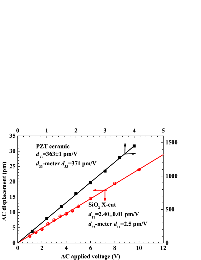
From Fig.2(d), one can see that the noise level of the method shown in Fig.1(a) is on the order of approximately 1 nm. Using this method it is not easy to measure the displacement of thin film correctly, since the electric field induced displacement in the thin film normally falls within the range of noise level. To greatly improve the resolution of displacement measurement, we have proposed an AC method that is combined with a lock-in technique. The setup implementing the AC method is shown schematically in Fig.1(b). In this method, an AC field lower than the coercive field of the ferroelectric material is applied to the poled sample. This AC field leads to an AC displacement of the piezoelectric sample with the same frequency. The output of the AC displacement meter is then fed into a lock-in amplify (SIGNAL RECOVERY model 7265) to reduce the noise. Using this approach, we can detect an AC displacement of pm reliably. To examine reliability of this method, we have used X-cut quartz as a stand because X-cut quartz is a piezoelectric crystal but not a ferroelectric crystal, its piezoelectric coefficient is not affected by polarization domain and has been widely reported in the literatures.Bottom ; Pan ; Kholkin The AC displacement of X-cut quartz as a function of AC applied voltage is shown in Fig.3. From the linear fit, of X-cut quartz is evaluated to be pm/V. While the -meter gives a value of 2.5 pm/V for the same sample. The known values for X-cut quartz are 2.3-2.4 pm/V.Bottom ; Pan ; Kholkin Comparing these values we can conclude that our AC displacement measurement system is highly reliable. The reliability of the measurement system is further confirmed by the result of the PZT ceramics sample used in Fig.2, which is also shown in Fig.3. The AC method gives a value of pm/V for the applied AC voltage up to 4 V. This value is consistent with that shown in Fig. 2(d) and obtained by the -meter. Also, it can be seen clearly from Fig.3 that at least 2 pm displacement can be exactly determined by our AC capacitive displacement measurement.
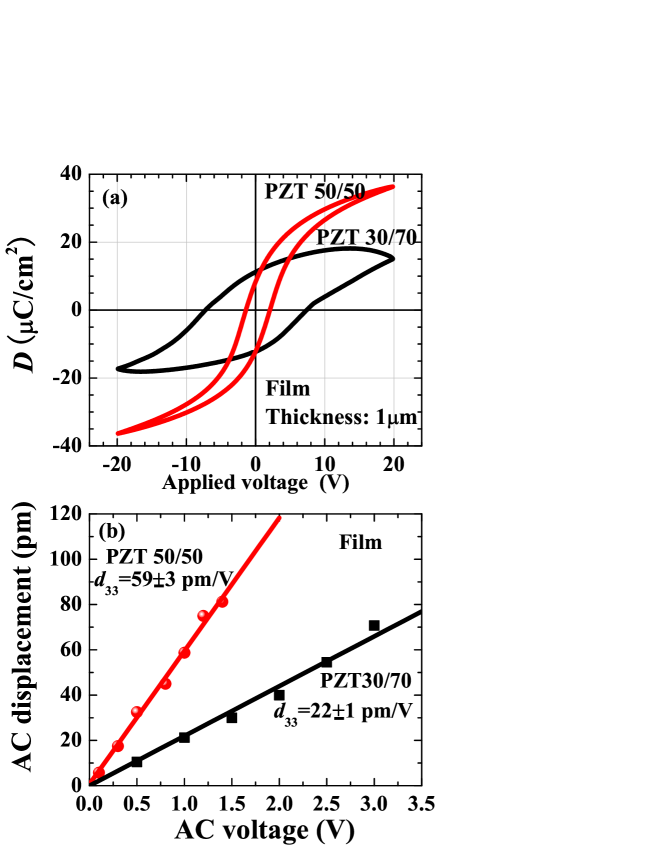
After examining the reliability of our AC capacitive displacement method, we then used it to test two kinds of PZT thin films (PZT50/50 and PZT30/70). PZT50/50 and PZT30/70 films have a composition of and , respectively. These PZT films were prepared by a chemical solution deposition on a silicon substrate with a Pt bottom electrode for capacitor fabrication. To form a capacitor, a top electrode with diameter of 1 mm was coated by Au. For the convenience of measurements, the back side of silicon substrate without PZT film was also coated by Au and connected to the Pt bottom electrode of PZT film. Figure 4(a) shows the D-E hysteresis loop of these two films, both of which have a similar value of remanent polarization of approximately of 10 C/cm2, indicating that these films are suitable for the piezoelectric measurements. The coercive fields were measured to be 2 V/m and 7.3 V/m for the PZT50/50 and PZT30/70 films, respectively. We then used an AC field less than to measure the AC displacement. The measurements were carried after D-E loop measurements which provided poling for the PZT films. The results are shown in Fig.4(b). values of PZT50/50 and PZT30/70 films were estimated to be pm/V and pm/V, respectively. These results suggests that PZT film with composition near MPB exhibits a large piezoelectric response that has Ti-rich composition. The lower values of PZT thin film as compared with ceramics samples may be affected by many factors such as film quality, orientation, poling process. However, detailed investigation of these effects is beyond the scope of the present study.
In summary, we have developed capacitive displacement measurement method to determine the longitudinal piezoelectric coefficient in both bulk and thin films reliably and simply. Using the AC method combined with the lock-in technique, we can precisely determine displacement as sall as 2 pm. This approach is expected to provide new insight into the piezoelectric properties of thin films which is still a challenging issue for the development of piezoelectric integrated technology.
Acknowledgements.
I thank Professor H. Suzuki in Shizuoka University for his kindly providing the PZT thin films for the test of my system.References
- (1) J. Curie and P.Curie, Bull. Soc. Fr.Mineral. 3, 90 (1880).
- (2) B. Jaffe, W. R. Cook Jr., and H. Jaffe, Piezoelectric ceramics, (Academic, London, Great Britain, 1971).
- (3) M. E. Lines and A. M. Glass, Principle and Application of Ferroelectrics and Related materials, (Clarendon, Oxford, Great Britain, 1977).
- (4) K. Uchino, Piezoelectric Actuators and Ultrasonic Motors, (Kluwer Academic Publishers, Norwell, MA 1997).
- (5) D. Fu, M. Endo, H. Taniguchi, T. Taniyama, and M. Itoh, Appl. Phys. Lett. 90, 252907 (2007).
- (6) D. Fu, M. Itoh, S. Koshihara, T. Kosugi, and S. Tsuneyuki, Phys. Rev. Lett. 100, 227601 (2008).
- (7) D. Fu, M. Itoh, and S. Koshihara, Appl. Phys. Lett. 93, 012903 (2008).
- (8) J. Rödel, W. Jo , K. T. P. Seifert, E. M. Anton, and T. Granzow, J. Am. Ceram. Soc. 92, 1153 (2009).
- (9) R. Tazaki, D. Fu, M. Itoh, M. Daimon, and S. Koshihara, J. Phys.: Condens. Matter. 21, 215903 (2009).
- (10) D. Fu, M. Endo, H. Taniguchi, T. Taniyama, M. Itoh, and S. Koshihara, J. Phys.: Condens. Matter. 23, 075901 (2011).
- (11) D. Fu, T. Arioka, H. Taniguchi, T. Taniyama, and M. Itoh, Appl. Phys. Lett. 99, 012904 (2011).
- (12) D. Fu, Y. Kamai, N. Sakamoto, N. Wakiya, H. Suzuki and M. Itoh, J. Phys.: Condens. Matter. 25, 425901 (2013).
- (13) P. Muralt, M. Kohli, T. Maeder, A. Kholkin, K. Brooks, N. Setter, R. Luthier, Sensors and Actuators A: Physical 48, 157 (1995).
- (14) P. Muralt, Integrated Ferroelectrics 17, 297 (1997).
- (15) D. Damjanovic, Rep. Prog. Phys. 61, 1267 (1998).
- (16) D. L. DeVoe, Sensors and Actuators A 88, 263 (2001).
- (17) W. Y. Pan, and L. E. Cross, Rev. Sci. Instrum. 60, 2071 (1989).
- (18) K. Lefki and G. J. M. Dormans, J. Appl. Phys. 76, 1764 (1994).
- (19) I. Kanno, S. Fujii, T. Kamada, and R. Takayama, Appl. Phys. Lett. 70, 1378 (1997).
- (20) A. L. Kholkin, Ch. Wütchrich, D. V. Taylor, and N. Setter, Rev. Sci. Instrum. 67, 1935 (1996).
- (21) J. A. Christman, R. R. Woolcott, Jr., A. I. Kingon, and R. J. Nemanich, Appl. Phys. Lett. 73, 3851 (1998).
- (22) F. Xu, F. Chu, and S. Trolier-McKinstry, J. Appl. Phys. 86, 588 (1999).
- (23) C. Durkan, D. P. Chu, P. Migliorato, and M. E. Welland, Appl. Phys. Lett. 76, 366 (2000).
- (24) O. Kuffer, I.Maggio-Aprile, J.-M. Triscone, O. Fischer, and Ch. Renner, Appl. Phys. Lett. 77, 1701 (2000).
- (25) D. Fu, K. Ishikawa, M. Minakata, and H. Suzuki, Jpn. J. Appl. Phys. 40, 5683 (2001).
- (26) G.-T. Park, J.-J. Choi, J. Ryu, H. Fan, and H.-E. Kima, Appl. Phys. Lett. 80, 4606 (2002).
- (27) V. E. Bottom, J. Appl. Phys. 41, 3941 (1970).