Photonic crystal with left-handed components
Abstract
We show that the periodic array of left-handed cylinders possesses a rich spectrum of guided modes when the negative permeability of cylinders equals exactly to minus value of permeability of embedding media. These resonances strongly influences propagation of electromagnetic waves through photonic structures made from left-handed materials. A series of Fano resonances excited by incident wave destroys the band frequency spectrum of square array of left-handed cylinders and increases considerably the absorption of transmitted waves.
keywords:
Left-handed materials, Fano resonances, Photonic structuresPACS:
42.70.Qs, 78.67.Pt1 Introduction
Left-handed (LH) materials which possess, in certain frequency interval, simultaneously negative electric permittivity and magnetic permeability exhibit interesting physical and optical properties, not observed in standard dielectrics or metals [2, 3, 4]. Although LH materials are not commonly available in nature, they may be prepared in laboratories and used for construction of devices with prescribed optical properties.
Physical and optical properties of LH materials have been studied during last 15 years from two different points of view. The first, microscopic, approach concentrates on the analysis of the design of individual “atoms” from which periodic macroscopic LH structure is constructed. The aim of this research is to optimize the structure of individual “atom” with respect to its resonant response which guarantee required properties of resulting macroscopic material [5, 6, 7, 8]. The second, macroscopic, approach considers homogeneous LH medium with negative and and investigates its physical properties as well as possible application of LH material in various photonic devices. Typical example of these studies are detailed theoretical and numerical investigations of one dimensional layered structures composed from alternating LH and dielectric layers [9, 10, 11, 12].
Recently it has been shown that components made from LH materials may strongly influence optical properties of 2D photonic structures and lead to unexpected phenomena, not observable in conventional photonic structures made from dielectric materials. For instance, the square periodic array of cylinders made from LH material can possess a non-standard band frequency spectrum which contains the so-called folded bands [13, 14]. Such results motivates further investigation how the application of LH materials influences the functionality of optical composites.
In this Paper we discuss another unusual property of LH photonic structures. We consider periodic arrangements of LH cylinders shown in Fig. 1 and calculate numerically the frequency dependence of the transmission coefficient of incident electromagnetic (EM) wave. Instead of regular transmission bands and gaps, typical for spectra of spatially periodic dielectric structures [15, 16], we observe, for small frequencies, a series of irregular maxims and minims in the frequency dependence of transmission coefficient. An example of such irregular frequency dependence is shown in Fig. 2(b). We show that physical origin of these irregularities lies in the excitation of high number of leaky eigenmodes of the structure and consequent interference of excited field with incident electromagnetic field [17, 18, 19]. Similar resonances were observed previously in dielectric photonic structures [20] and their influence on the optical response has been analyzed in Refs. [21, 22, 23]. We found that the spectrum of excited resonances strongly depends on actual values of negative permittivity and permeability and is extremely rich if one of these parameters coincides with the minus value of the corresponding parameter of embedding media.


(a) (b)


The Paper is organized as follows. In Sect. 2, we calculate transmission coefficient of perpendicularly incident EM wave propagating across the linear array of cylinders and through slab constructed from finite number of parallel arrays. We identify a series of resonances in the frequency dependence of transmission coefficient. To find their physical interpretation, we analyze the complete spectrum of guided modes of the linear chain of cylinders and show that maxima and minima of the transmission coefficient are associated with Fano resonances excited in the photonic structure by incident EM wave. In Section 3 we study how the electromagnetic response of the structure depends on material parameters: radius of cylinders, magnetic permeability and absorption. Of particular interest is the model with frequency dependent negative permittivity and permeability which also exhibit a series of resonances in the transmission spectra in the frequency interval where either permittivity or permeability approaches the value -1. Since the the resonance causes a strong enhancement of electromagnetic field inside the structure, we calculate the absorption of transmitted wave. Conclusion is given in Sect. 4. Finally, numerical method used for the calculation of the transmissions coefficient is described in Appendices.
2 Linear chain of left-handed cylinders
In this Section, we study the response of linear chain of LH cylinders to incident electromagnetic wave. The structure, shown in Fig. 1(a), consists from an infinite periodic chain of cylinders embedded in the vacuum with permittivity and permeability . The spatial periodicity of the structure along the direction, given by distance between neighboring cylinders, defines the length unit. Cylinders are infinite along the direction and are made from homogeneous material with relative permittivity and permeability .
Incident plane wave with wavelength propagates along the direction. We calculate the transmission and reflection coefficient as a function of dimensionless frequency . The method is described in Appendix A. Here we only note that electromagnetic field is expanded in series of cylinder functions [24] given by Eqs. (6) and (7). Expansion coefficients and are calculated from the requirement of continuity of tangential components of electric and magnetic intensity at the boundary of cylinders.
The frequency dependence of the transmission coefficient of the -polarized plane EM wave for both dielectric and LH cylinders is shown in top panels of Figs. 2(a,b). For dielectric cylinders, we identify three deep minima in which correspond to Fano resonances excited by incident wave [17, 23]. Similar resonances were found in the LH structure, but their number is much higher and resonant frequencies are located in the region of small frequencies . Detailed frequency dependence of the transmission coefficient is given in Fig. 3.
Lower panels of Figs. 2(a,b) display the transmission coefficient for photonic slabs composed from 3, 6 and 24 rows of cylinders. For dielectric cylinders, Fano resonances develop to narrow Fano bands discussed in details in Ref. [23]. In contrast, a high number of Fano resonances in the LH structure, completely destroy the band structure. Regular transmission band, typical for periodic media, is observed only for higher frequencies .

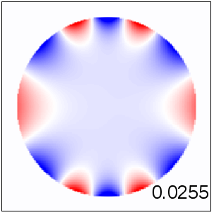
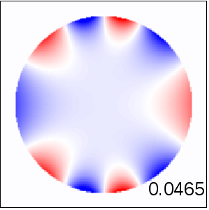
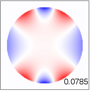
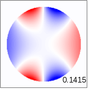
propagation of polarized EM wave
Following Ref. [23] we expect that the strong irregularities in transmission spectra of linear chain of cylinders are caused by excitation of resonances in the structure. To verify this conjecture, we calculate how coefficients , which measure the amplitude of excited resonances (Eq. 7) depend on the frequency of incident wave. We found, in agreement with Fig. 3(a), a series of strong resonances, associated with sharp narrow maxims in (Fig. 3(c,d)). Resonant frequencies coincides with positions of minims in transmission coefficient. Note that owing to even symmetry of perpendicularly incident plane EM wave, only resonances symmetric with respect to transformation were excited [25]. Resonant frequencies lye very close to each other (note logarithmic scale of horizontal axis). Comparison of panels (a,b) with (b,c) confirms that each observed transmission minimum corresponds to Fano resonant frequencies.
Data shown in Fig. 3 enable us to identify exponential decrease of resonant frequency when increases:
| (1) |
with constant .
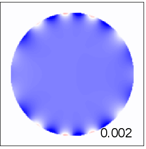
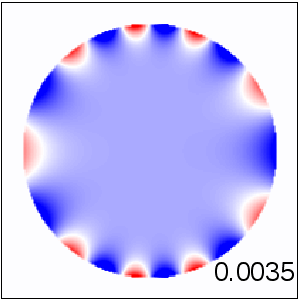
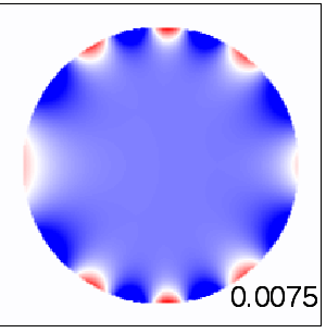
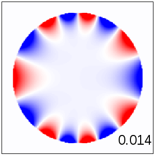
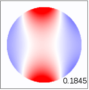
Figure 4 displays spatial distribution of electric field inside LH cylinders for nine resonant frequencies identified in Fig. 3. The field concentrated close to the boundary of cylinders. The spatial distribution of field along the boundary reminds us the circular standing waves with the wavelength
| (2) |
Similar inhomogeneous spatial distribution of EM field has been found also in other photonic systems which contains LH cylinders [28].
2.1 Eigenmodes

Resonances observed in the transmission spectra are given by excitations of eigenmodes of the photonic structures [17]. We calculate the dispersion of guided modes propagating along the linear chain of LH cylinders with wave vector and frequency . To find the dispersion curves , we start with two systems of linear equations for coefficients and , (17) and (18) with zero right-hand side. Instead of solving these homogeneous systems of equations, we calculate the determinant as a function of frequency [26]. With the use the Gauss-Jordan elimination method [27] we transform the matrices in the l.h.s of Eqs. (17) and (18) into diagonal form and plot the frequency dependence of inverse of obtained diagonal matrix elements. This enables us not only to find the eigenfrequency and lifetime of a given of guided mode but also to identify its order . Note that method enables us to calculate both guided modes with and leaky modes () with finite lifetime [26].
Figure 5 presents the dispersion curves of guided modes. For comparison, the spectrum of guided modes of an array of dielectric cylinders is shown in the Inset. As expected, the spectrum for left-handed cylinders is more complicated. In contrast to dielectric cylinders [23], the number of guided modes is much higher. The number of modes depends on the model parameters and increases when absolute value of the refractive index increases (data not shown). In agreement with Eq. (1), their eigenfrequencies decreases when the mode index increases.
Another unexpected property of spectra of guided modes is the existence of ”critical value” of the wave vector ( in our model) for which no guided mode exists (Figure 5). Analysis of another left-handed structures with (data not shown) indicates that depends neither on (negative) permittivity nor on the radius of cylinder.
3 Parameters of the model
In this Section we investigate how the spectrum of resonant modes depends on the parameters of the model.
3.1 Radius of cylinder
Very narow resonances in the transmission coefficient for the frequency as well as broad minimum of the transmission at shown in Fig. 6(a) indicate that Fano resonances can be observed already in the linear chain of very tiny () LH cylinders. The transmission coefficient of photonic slab exhibits a broad gap for small frequencies with a few narrow resonances at small frequencies . Broad transmission band, typical for periodic structures, started at .
Figure 6(b) shows that the frequency dependence of the transmission coefficient is more dramatic when the radius of cylinders increases. For the polarized wave, the frequency dependence of is highly irregular, indicating the high number of resonances in the structure. Only for higher frequency, regular transmission band is observed.
Note that in contrast to the waves, the transmission coefficient for the wave typical frequency dependence typical for dielectric photonic crystals, independently on the cylinder radius. As we will see later, the absence of Fano resonances is due to big difference in absolute values of the permittivity inside cylinders and permittivity of the embedding medium.
(a) R = 0.1

(b) R = 0.2

3.2 Permeability
Photonic structures discussed up to now possess LH components with effective permeability equal exactly to minus value of the permeability of the embedding media. This coincidence might be responsible for strong resonances of electromagnetic field observed in previous Sections. We note that spatial distribution of the EM field with high values of the intensity close to cylinder boundary (Fig. 4) is similar to surface plasmons excited at the planar interface of vacuum and LH media [30] and that the dispersion relation of the polarized surface plasmon wave (with electric field parallel to the interface) is singular when the permeability equals to minus value of permeability of embedding media [30, 31]. Of course, the analogy is not exact since, in contrast to our resonant states, surface plasmon cannot be excited by incident EM wave.
Figure 7 shows the transmission coefficients and spectra of coefficients for linear chain of LH cylinders with permeability slightly below and above the critical value . The positions of resonances in frequency spectra are very sensitive to the actual value of : for smaller (in absolute value) , resonances shift to frequencies , while for larger values of permeability they disappear.


3.3 Dispersive LH materials

Since realistic LH materials are dispersive [2], it is important to generalize our analysis to structures made from dispersive LH materials. We consider LH cylinders with frequency dependent permittivity
| (3) |
and permeability
| (4) |
Transmission coefficient for arrays of such cylinders is shown in Fig. 8 both for the and polarized EM waves.
For small frequency the permittivity is negative and permeability is positive. The transmission coefficient exhibits the frequency dependence typical for an array of metallic cylinders [29] with low frequency transmission gap for the polarized wave and regular transmission band for the polarized wave. Irregular frequency dependence for slightly above is due to the large value of the effective index LH material. More interesting is the transmission coefficient for the polarized wave in the frequency region around defined by relation which exhibits irregular frequency dependence similar to that discussed in Sect. 2. Similar resonant behavior is observed for the -polarized wave in the vicinity of frequency , where the permittivity of LH material approaches minus unity.
3.4 Absorption
As discussed in [23], high intensity of EM field inside cylinders may cause strong enhancement of the absorption of transmitted EM wave for frequencies close to resonant Fano frequency. Figure 9 demonstrates an increase of the absorption in photonic structures with LH cylinders. Absorption is close to unity already for very small values of imaginary part of permittivity and permeability, Imag . Since Fano resonances lye close to each other, we obtained broad absorption band with absorption coefficient close to unity.

4 Conclusion
We have shown that transmission spectra of photonic structures with LH components might be strongly influenced by Fano resonances excited by incident electromagnetic wave. Fano resonances play an important role especially when the permittivity and/or permeability of the LH material is close to . As such values exists in any realistic dispersive LH medium, we expect that irregular resonant behavior, discussed in this paper, might be observed experimentally. However, non-zero imaginary part of permittivity and permeability strongly enhanced absorption losses due to large amplitudes of electromagnetic waves inside cylinders. Therefore, instead of irregular resonant transmission, found numerically in loss-less materials, we expect that a broad absorption band in the resonant frequency region will be measured.
We also found that the spatial distribution of the electromagnetic field inside the cylinders is highly inhomogeneous with strong field enhancement in the narrow region in the vicinity of the boundary of cylinder.
This work was supported by the Slovak Research and Development Agency under the contract No. APVV-0108-11 and by the Agency VEGA under the contract No. 1/0372/13.
Appendix A Numerical methods
In this Section we describe the numerical method used for the calculation of the transmission of electromagnetic wave with wavelength propagating across linear chain of cylinders shown in Fig. 1(a). Owing to the cylinder symmetry, we express electric and magnetic fields in cylindrical coordinates. Consider the -polarized electromagnetic wave, (the polarized wave an be treated in the same way). Two non-zero components of the magnetic field, the angular, , and the radial, , ones can be found with the use of Maxwell equations [32]
| (5) |
For cylinder centered in we express the electric intensity as a sum of cylinder functions [24]. Inside the cylinder () we have
| (6) |
where is Bessel function of integer order, , and is the index of refraction. Coefficients and determine amplitudes of even () and odd () cylindrical waves, respectively. In Eq. (6), as well in all expressions below, the sumation over is restricted to lowest order cylinder functions ().
The electric field outside the cylinder consists from three contributions: the first one is the field scattered on the cylinder itself [24]
| (7) |
The second contribution to the external fields consists from fields scattered on other cylinders present in the structure. In particular, the contribution of the th cylinder () expressed as a function of coordinates associated with its center (Fig. 10) reads
| (8) |
Note that coefficients differs from defined in Eq. (A.3). However, thanks to the periodicity of the structure along the axis, we can use the Bloch’s theorem and express of the th cylinder in terms of coefficients as
| (9) |
where is the -component of the wave vector of EM field.
Finally, the third contribution is given by incident electromagnetic wave. For instance, the plane wave incident perpendicularly to the cylinder chain (Fig. 1(b)) can be expressed as a sum of Bessel function [33]
| (10) |

Unknown coefficients and defined in Eqs. (A.2-A.4) are calculated from the requirement of the continuity of tangential components of electric and magnetic fields at the boundary of each cylinder. Thanks to Eq. (A.5), it is sufficient to formulate the continuity conditions only for the cylinder located at the center of coordinates. Since is parallel to cylinder surface, the requirement of the continuity of electric field is easy to formulate,
| (11) |
The continuity condition for the magnetic field is expressed in more complicated form
| (12) |
where the angle .

Before solving this system of equations, we express all fields in Eq. (8) in terms of variables and associated with the cylinder located at the point , . This can be done with the use of the Gegenbauer formula for cylindrical functions (Fig. 11)
| (13) |
and their derivative :
| (14) |
[33]. Inserting (14) into Eq. (8) we express, after some algebra, the fields at the outer boundary of the cylinder in the form
| (15) |
and
| (16) |
Explicit expressions for matrices B, B’, C and C’ are given in Appendix B.
In the next step, we eliminate coefficients from Eqs. (A.11) and (A.12) and obtain two separate systems of linear equations for coefficients and :
| (17) |
, and
| (18) |
. Here, and
| (19) |
is the impedance of cylinders. In numerical analysis, we consider the number of cylinders and number of modes .
Transmission coefficient can be calculated as the ratio of the -component of the Poynting vector , calculated for any to the incident Poynting vector,
| (20) |
where
| (21) |
and
| (22) |
Similarly, reflection coefficient is given by
| (23) |
Where
| (24) |
calculated for .
Appendix B Matrices B and C
With notation and , we express the explicit form of the matrix B
| (25) |
(). The matrix C has a form
| (26) |
Matrices B’ and C’ could be obtained from B and C, respectively, by substitutions
| (27) |
Appendix C System with rows of cylinders
If the system consists of rows of cylinders (the th row lies in plane ), then we have to define sets of parameters , each for the th cylinder along the direction. The method of calculation remains the same as for the linear chain with , but resulting linear relations between coefficients are more complicated. In particular, it is not possible to separate coefficients and . Resulting system of linear equations for coefficients is of the size ). For (typically used in numerical simulations) and the problem reduces to the solution of 600 linear equations.
References
- [1]
- [2] V. G. Veselago, Sov. Phys. Usp. 10, 509 (1968).
- [3] J. B. Pendry, Phys. World 14, 47 (2001); J. B. Pendry, Contemp. Phys. 45, 191 (2004).
- [4] N. Engheta and R. W. Ziolkowski (Editors), Metamaterials: Physics and Engineering Explorations, New York: J. Wiley & Sons (2006)
- [5] R. A. Shelby, D. R. Smith S. and Schultz, Science 292, 77 (2001).
- [6] J. B. Pendry, Phys. Rev. Lett. 85, 3966 (2000).
- [7] J. B. Pendry, D. Schurig and D. R. Smith, Science 312, 1780 (2006).
- [8] N. I. Landy, S. Sajuyigbe, J. J. Mock, D. R. Smith and W. J. Padilla, Phys. Rev. Lett. 100, 207402 (2008).
- [9] J. Li, L. Zhou, C. T. Chan, P. Sheng, Phys. Rev. Lett. 90 083901 (2003).
- [10] S. A. Ramakrishna, J. B. Pendry, M. C. K. Wiltshire, J. Mod. Opt. 50, 1419 (2003).
- [11] S. A. Gredeskul Y. S. Kivshar A. A. Asatryan, K. Y. Bliokh, Y. P. Bliokh, V. D. Freilikher and I. V. Shadrivov, Low Temp. Phys. 38, 570 (2012).
- [12] P. Markoš and R. Hlubina unpublished
- [13] P. Y. Chen et al., New J. Phys. 13 053007 (2011).
- [14] D. Hermann et al, Phys. Rev. B 77 035112 (2008).
- [15] J. D. Joannopoulos, S. G. Johnson, J. N. Winnand R. G. Meade, Photonic Crystals: Molding the Flow of Light, 2nd edition. Princeton: Princeton University Press (2008).
- [16] K. Sakoda, Optical Properties of Photonic Crystals, Berlin, Heidelberg: Springer (2005).
- [17] S. Fan and J. D. Joannopoulos, Phys. Rev. B 65 235112 (2002).
- [18] S. Fan, W. Suh and J. D. Joannopoulos, J. Opt. Soc. Amm. A 20 569 (2003).
- [19] M. V. Rybin, K.B. Samusev, I. S. Sinev, G. Semouchkin, E. Semouchjina, Y. S. Kivshar, M. F. Limonov, Optics Express 21, 30107 (2013).
- [20] K. Ohtaka, H. Numata, Phys. Lett. 73A, 411 (1979).
- [21] A. A. Poddubny et al, Nature Communications 3:914 (2012).
- [22] B. Lukyanchuk et al, Nature Materials 9 707 (2010).
- [23] P. Markoš, Phys. Rev. A (2015) to appear.
- [24] J. A. Stratton, Electromagnetic Theory New York: Mc Graw-Hill Comp. (1941).
- [25] W. M. Robertson et al., Phys. Rev. Lett. 68 2023 (1992).
- [26] C. A. Pfeiffer, E. N. Economou and K. L. Ngai, Phys. Rev. B 10, 3038 (1974).
- [27] W. H. Press et al, Numerical Recipes Cambridge: Cambridge University Press (1992).
- [28] A. A. Asatryan, K. B. Dossou and L. C. Botten, Australian Institute of Physics, 18th national Congress (2008).
- [29] J. B. Pendry et al. Phys. Rev. Lett. 76 4773 (1996).
- [30] P. Markoš and C. M. Soukoulis, Wave Propagation: From Electrons to Photons and Left-handed Materials, New Jersey Princeton Univ. Press (2008).
- [31] T. Vary, P. Markoš: Physica B 405, 2982 (2010)
- [32] J. D. Jackson: Classical Electrodynamics New York: John Willey and Sons (1999).
- [33] M. Abramowitz and I. A. Stegun, Handbook of Mathematical Functions Dover Publ. (1965).