Optically controlled periodical chain of quantum rings
Abstract
We demonstrated theoretically that a circularly polarized electromagnetic field substantially modifies electronic properties of a periodical chain of quantum rings. Particularly, the field opens band gaps in the electron energy spectrum of the chain, generates edge electron currents and induces the Fano-like features in the electron transport through the finite chain. These effects create physical prerequisites for the development of optically controlled nanodevices based on a set of coupled quantum rings.
pacs:
73.21.-b,73.23.-bI Introduction
Progress in fabrication of semiconductor nanostructures has led to achievements in studies of various ring-like mesoscopic objects, including quantum rings, nanotubes, nanohelices (see, e.g., Refs. [Fomin, ; Saito, ; Prinz_00, ; Kibis_92, ]). The physical interest to the rings is caused by the phenomenon of the interference of electron waves, which can be observed there. Particularly, the Aharonov-Bohm (AB) effect arisen from the direct influence of the vector potential on the phase of the electron wave function AB_Chambers1960 ; ABoriginal ; AB_prallel_1984 ; AB_topology has been studied both theoretically and experimentally in various ring-like nanostructures AB_ballistic_exp_1 ; AB_ballistic_exp_2 ; AB_ballistic_exp_3 ; AB_ballistic_exp_4 ; AAS_exp1 ; AASExp2 ; AB_WeakLoc2 ; AB_WeakLoc3 ; AB_bal_WL_2005 . Conceptually, the AB effect is caused by the broken time-reversal symmetry in an electron system subjected to a magnetic flux. Namely, the flux breaks the physical equivalence of clockwise and counterclockwise electron rotations in a ring, which results in the flux-controlled interference of the electron waves corresponding to these rotations. However, the time-reversal symmetry can be broken not only by a magnetic flux but also by a circularly polarized electromagnetic field. Therefore, the strong coupling of electrons in quantum rings to off-resonant circularly polarized photons leads to the optically induced AB effect dressing_kibisprl ; Kibis_14 ; Shelykh2014AB_opt ; exciton_kibis . As a consequence, stationary electronic properties of quantum rings can be effectively controlled with light. It should be noted that the optical control of quantum rings is attractive from applied viewpoint since it is much faster than the magnetic-flux-induced control. Therefore, optically-controlled ring-like nanostructures can be considered as a basis for creating ultra-fast logic gates. In the previous studies, the main attention was paid to the optically induced effects in sole quantum rings. As to the effects in multi-ring systems, they escaped attention before. In the present article, we perform theoretical analysis of an one-dimensional chain of coupled quantum rings QRchain00 ; Chains11 ; ChainsFib ; Chains7 subjected to an off-resonant circularly polarized electromagnetic wave and demonstrate that electronic properties of the chain are very sensitive to the irradiation.
II Model
Let us consider the periodical chain of quantum rings irradiated by a circularly polarized electromagnetic wave with the electric field amplitude and the frequency , which is assumed to be far from resonant frequencies of the electron system (see Fig. 1).
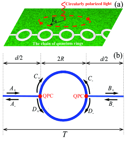
Within the scattering matrix approach AB_bal_WL_2005 ; Butticker1984 , the amplitudes of electron waves in the chain, , , , , satisfy two equations,
| (1) |
| (2) |
where the scattering matrix is
| (3) |
is the electron transmission amplitude through the QPCs (), is the electron wavenumber, is the electron mass, and is the electron energy. As to the phase shift in Eqs. (1) and (2),
| (4) |
it describes the phase difference for electron waves traveling inside the ring clockwisely and counterclockwisely, which arises from the electron coupling to the circularly polarized irradiation Shelykh2014AB_opt . It should be stressed that the phase shift (4) is induced by an off-resonant electromagnetic field (“dressing field” in conventional terms of quantum optics) which cannot be absorbed by electrons. Therefore, the effects discussed below substantially differ from the effects caused by absorption of light in quantum rings (see, e.g., Refs. [Pershin_2005, ; Rasanen_2007, ; Matos_2005, ]).
Applying the Bloch theorem to the considered periodic chain of quantum rings, we arrive at the equation
| (5) |
where is the electron wave vector originated from the periodicity of the chain and is the period of the chain. Mathematically, Eqs. (1), (2) and (5) form a homogeneous system of linear algebraic equations for the eight amplitudes . The secular equation of the algebraic system,
| (6) | ||||
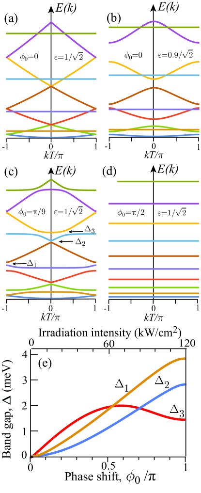
defines the sought electron energy spectrum of the irradiated chain, , which is plotted in Fig. 2 for the particular important cases discussed below.
III Discussion and conclusions
The electron energy spectrum of the chain without the irradiation () is shown in Figs. 2(a)–(b). In the case of transparent QPCs (), Eq. (6) reads as
| (7) |
Evidently, Eq. (7) has the two solutions, and , where . The first solution produces the -dependent branches of the electron energy spectrum, , which correspond to an electron propagating along the chain, whereas the second one results in flat bands corresponding to an electron localized inside individual rings [see Fig. 2(a)]. In the case of semitransparent QPCs (), the secular equation (6) takes the form
| (8) |
It follows from Eq. (III) that the non-transparency of the QPCs leads to opening band gaps at the Brillouin zone edges (), which arise from the Bragg reflection of electron waves by the QPCs [see Fig. 2(b)]. As to the limit of weakly transparent QPCs, , the band structure contains only the electron modes localized inside rings and leads, which are defined by the dispersion equation .
The electron energy spectrum of the irradiated chain () is shown in Figs. 2(c)–(d). Since the localized electron modes are not eigenmodes of the irradiated structure, the phase shift results in the coupling between the localized electron modes of the rings and the propagating electron modes of the chain. As a consequence, the anticrossings — which manifests itself through opening of the additional band gaps inside the Brillouin zone — appears [see Fig. 2(c)]. It should be noted also that in the particular case of Eq. (6) results in the series of the -independent solutions producing flat bands in Fig. 2(d). Thus, generally, the two types of the band gaps can be identified in the considered chain: The type-I gaps can take place in the unirradiated chain, whereas the type-II gaps are caused by the irradiation. Namely, the type-I gaps, and , are opened at edges and at the center of the Brillouin zone, whereas the type-II gaps, , appear at the crossing of delocalized and localized electron modes [see Fig. 2(c)]. It should be noted that these two types of the band gaps have different dependence on the small phase shifts : While the type-I gaps are , the type-II gap is . The explicit forms of the asymptotic expressions for the gaps at read as
| (9) | |||
| (10) | |||
| (11) |
The dependence of gaps on the phase shift is plotted in Fig. 2(e). The irradiation-induced type-II gaps are most interesting from viewpoint of possible applications since they allow to design the optically-controlled modulators of the electron signal propagating in the chain.
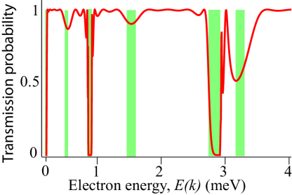
It should be noted that the coupling of the narrow localized electron mode and the delocalized one, which results in opening the type-II band gaps, can be described formally in terms of the Fano resonance Fano1961 ; Fano_Rev . In order to demonstrate this, we calculated the probability of electron transmission through a finite chain of quantum rings (see the Appendix). The Fano-like asymmetry of the lineshape of the transmission spectrum is clearly seen in Fig. 3.
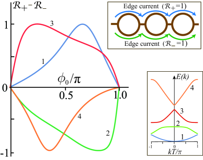
In order to demonstrate another interesting irradiation-induced effect in the considered system, let us introduce the probabilities to find the electron in upper and lower segments of rings, . The difference of these probabilities, , which gives the distribution of electron density in the chain, is plotted in Fig. 4 as a function of the phase shift, . It follows from the plot that an electron in the irradiated chain propagates preferably either in the upper or the lower segments of the rings. Moreover, one can see that for some values of . As a consequence, electrons propagating along the chain can be localized in different (upper or lower) segments of the rings. Thus, the irradiation-induced edge currents appear (see the upper insert in Fig. 4).
In the present paper, we restricted our consideration by the simplest case of the periodic chain consisting of identical rings. It is interesting to discuss the more complicated case of the doubly-periodic chain, where the unit cell of the periodic structure consists of two non-equivalent quantum rings. In this case, the simultaneous breakdown of the time-reversal symmetry (due to the applied circularly polarized field) and the inversion symmetry (due to non-equivalency of the rings) takes place. It follows from the fundamentals of quantum mechanics that these broken symmetries result in the asymmetric electron dispersion, , which has been studied in various nanostructures (see, e.g., Refs. Kibis2001_nanotubes, ; Lawton2002_rectification, and references therein). As a consequence, electronic phenomena which are specific for such an asymmetric dispersion can be expected also in the system under consideration.
Finalizing the discussion, let us analyze observability of the predicted effects. There are the two fundamental restrictions for the developed theory. Firstly, the mean free path of electron for inelastic scatterring processes should be much greater than the chain period . Secondly, the condition of strong electron-field coupling must be satisfied: The time of electron travelling through a ring should be much less than the field period, Shelykh2014AB_opt . In the considered case of GaAs-based quantum rings with the Fermi energy of meV scale and the chain period m, the both conditions can be satisfied for a dressing field of THz frequency range with the intensity W/cm2. It follows from the calculations that the field-induced band gaps are of meV scale [see Fig. 2(e)] and, therefore, can be easily detected in state-of-the-art optical experiments. To use the irradiation frequencies within the visible and near-infrared ranges, the field intensity, , should be increased in order to keep the phase shift (4) to be large enough. However, increasing the field intensity can melt the nanostructure. To avoid the melting with the strong field, it is reasonable to use narrow pulses of a circularly polarized field which open band gaps and narrow pulses of a weak probing field which detect the gaps. This pump-and-probe methodology has been elaborated long ago and is commonly used to observe various effects induced by strong fields — particularly, modifications of electron energy spectrum arisen from the optical Stark effect — in semiconductor structures Joffre1 ; Joffre2 ; PumpProbe1 . Since giant field intensities (up to GW/cm2) can be applied to semiconductor structures within this approach, the wide band gaps can be opened with the pulsing fields.
Summarizing the aforesaid, we analyzed the electron dispersion and electron transport properties of an one-dimensional periodical chain of quantum rings irradiated by circularly polarized light. It is shown that the optically induced Aharonov-Bohm effect leads to opening band gaps in electron energy spectra of the chain and modifies electron transport through the chain. These findings can be exploited, for instance, in optically controlled logic gates with high operation speed.
The work was partially supported by FP7 IRSES projects POLATER and QOCaN, FP7 ITN project NOTEDEV, Rannis project BOFEHYSS, RFBR projects 14-02-00033 and 16-02-01058, the Russian Ministry of Education and Science, the Russian Target Federal Program “Research and Development in Priority Areas of Development of the Russian Scientific and Technological Complex for 2014-2020” (project 14.587.21.0020)
Appendix A Derivation of the transmission probability for a finite chain of quantum rings
In order to obtain the expression for the probability of electron transmission through a finite periodic chain of quantum rings (the transmission probability plotted in Fig. 4), we have to introduce the transfer matrix, , which connects the incoming electron amplitudes, , with the outgoing electron amplitudes, ,
| (12) |
It follows from the basic equations (1)–(2) that the transfer matrix for the elementary cell pictured in Fig. 1(b) reads as
| (13) |
The transfer matrix over elementary cells, , is just the -th power of the transfer matrix (13), i.e. . If the incoming amplitude is , we arrive from Eq. (12) to the equation
| (14) |
where and are the amplitudes of electron reflection and electron transmission through the chain, respectively. Taking into account the unimodularity property of the transfer matrices, the solving of Eq. (14) leads to the transmission amplitude
| (15) |
where
| (16) | |||||
and is the Chebyshev polynomial of the second kind Markos2008 . Using Eqs. (15) and (16), we can easily calculate the transmission probability, , plotted in Fig. 4.
References
- (1) V. M. Fomin (ed.), Physics of Quantum Rings (Springer-Verlag, Berlin, 2014).
- (2) R. Saito, G. Dresselhaus, M. S. Dresselhaus, Physical Properties of Carbon Nanotubes (Imperial College Press, London, 1998).
- (3) V. Y. Prinz, V. A. Seleznev, A. K. Gutakovsky, A. V. Chehovskiy, V. V. Preobrazhenskii, M. A. Putyato, T. A. Gavrilova, Physica E 6,828 (2000).
- (4) O. V. Kibis, Phys. Lett. A 166, 393 (1992).
- (5) Y. Aharonov, D. Bohm, Phys. Rev. 115, 485 (1959).
- (6) R. G. Chambers, Phys. Rev. Lett. 5, 3 (1960).
- (7) Y. Gefen, Y. Imry, and M. Y. Azbel, Phys. Rev. Lett. 52, 129 (1984).
- (8) L. Duca, T. Li, M. Reitter, I. Bloch, M. Shleier-Smith, and U. Schneider, Science 347, 288 (2014).
- (9) R. A. Webb, S. Washburn, C. P. Umbach, and R. B. Laibowitz, Phys. Rev. Lett. 54, 2696 (1985)
- (10) G. Timp, A. M. Chang, J. E. Cunningham, T. Y. Chang, P. Mankiewich, R. Behringer, and R. E. Howard, Phys. Rev. Lett. 58, 2814 (1987).
- (11) D. Vegvar, G. Timp, P. M. Mankiewich, R. Behringer, and J. Cunningham, Phys. Rev. B 40, 3491 (1989).
- (12) B. J. van Wees, L. P. Kouwenhoven, C. J. P. M. Harmans, J. G. Williamson, C. E. Timmering, M. E. I. Broekaart, C. T. Foxon, and J. J. Harris, Phys. Rev. Lett. 62, 2523 (1989).
- (13) B. Pannetier, J. Chaussy, R. Rammal, and P. Gandit, Phys. Rev. B 31, 3209 (1985).
- (14) T. Bergsten, T. Kobayashi, Y. Sekine, and J. Nitta, Phys. Rev. Lett. 97, 196803 (2006).
- (15) D. Shavrin and Y. Shavrin, JETP Lett. 34, 272 (1981).
- (16) G. Bergmann, Phys. Rev. B 28, 2914 (1983).
- (17) I. A. Shelykh, N. T. Bagraev, N. G. Galkin, and L. E. Klyachkin, Phys. Rev. B 71, 113311 (2005).
- (18) O. V. Kibis, Phys. Rev. Lett. 107, 106802 (2011).
- (19) O. V. Kibis, O. Kyriienko, I. A. Shelykh, Phys. Rev. B 87, 245437 (2013).
- (20) H. Sigurdsson, O. V. Kibis, and I. A. Shelykh, Phys. Rev. B 90, 235413 (2014).
- (21) O. V. Kibis, H. Sigurdsson, and I. A. Shelykh, Phys. Rev. B 91, 235308 (2015).
- (22) J. Li, Z.-Q. Zhang, and Y. Liu, Phys. Rev. B 55, 5337 (1997).
- (23) C. P. Search, J. R. Toland, and M. Zivkovic, Phys. Rev. A 79, 053607 (2009).
- (24) A. Nomata and S. Horie, Phys. Rev. B 75, 115140 (2007).
- (25) A. Chakrabarti, R. A. Römer, and M. Schreiber, Phys. Rev. B 68, 195417 (2003).
- (26) M. Buttiker, Y. Imry, and M. Y. Azbel, Phys. Rev. A 30, 1982 (1984).
- (27) Y. V. Pershin, C. Piermarocchi, Phys. Rev. B 72, 245331 (2005).
- (28) E. Räsänen, A. Castro, J. Werschnik, A. Rubio, E. K. U. Gross, Phys. Rev. Lett. 98, 157404 (2007).
- (29) A. Matos-Abiaque, J. Berakdar, Phys. Rev. Lett. 94, 166801 (2005).
- (30) U. Fano, Phys. Rev. 124, 1866 (1961).
- (31) A. E. Miroshnichenko, S. Flach, and Y. S. Kivshar, Rev. Mod. Phys. 82, 2257 (2010).
- (32) For details of the calculations, see the Supplementary Information.
- (33) O. V. Kibis, Phys. Sol. State 43, 2336 (2001).
- (34) D. Lawton, A. Nogaret, M. Makarenko, O. V. Kibis, S. Bending, and M. Henini, Physica E 13, 699 (2002).
- (35) M. Joffre, D. Hulin, A. Migus, and A. Antonetti, J. Mod. Opt. 35, 1951 (1988).
- (36) M. Joffre, D. Hulin, A. Migus, A. Antonetti, C. Benoit la Guillaume, N. Peyghambarian, and K. S. Lindberg, Opt. Lett. 13, 276 (1988).
- (37) S. G. Lee, P. A. Harten, J. P. Sokoloff, R. Jin, B. Fluegel, K. E. Meissner, C. L. Chuang, R. Binder, S. W. Koch, G. Khitrova, H. M. Gibbs, N. Peyghambariam, J. N. Polky, and G. A. Pubanz, Phys. Rev. B 43, 1719 (1991).
- (38) P. Markos and C. M. Soukoulis, Wave propagation: From electrons to photonic crystals and left-handed materials (Princeton University Press, Princeton, 2008).