First Principles Investigation of Hydrogen Physical Adsorption on Graphynes’ layers
Abstract
Graphynes are 2D porous structures deriving from graphene featuring triangular and regularly distributed subnanometer pores, which may be exploited to host small gaseous species. First principles adsorption energies of molecular hydrogen (H2) on graphene, graphdiyne and graphtriyne molecular prototypes are obtained at the MP2C level of theory. First, a single layer is investigated and it is found that graphynes are more suited than graphene for H2 physical adsorption since they provide larger binding energies at equilibrium distances much closer to the 2D plane. In particular, for graphtriyne a flat minimum located right in the geometric center of the pore is identified. A novel graphite composed of graphtriyne stacked sheets is then proposed and an estimation of its 3D arrangement is obtained at the DFT level of theory. In contrast to pristine graphite this new carbon material allow both H2 intercalation and out-of-plane diffusion by exploiting the larger volume provided by its nanopores. Related H2 binding energies for intercalation and in-pore adsorption are around 0.1 eV and they could lead to high storage capacities. The proposed carbon-based layered material could represent a safer and potentially cheaper alternative for hydrogen on-board storage than conventional solutions based on cryogenic liquefaction and/or high compression.
KEYWORDS: hydrogen storage, graphynes, two-dimensional materials, ab initio calculations
I Introduction
Hydrogen is a clean-burning energy carrier which is supposed to provide the most promising alternative to fossil fuels to be employed in propulsion systems for automotive applications. However, some drawbacks such as the safe and convenient hydrogen storageZüttel (2004) and release in reversible cycles still represent major challenges to the scientific community. The use of advanced solid state adsorbents has recently received wide attention since they could provide solutions to achieve the 2017 targets for on-board vehicle hydrogen storage established by the U.S. Department of Energy (DOE): they are actually 5.5 wt% and 0.040 kg L-1 for gravimetric and volumetric capacities, respectivelyDOE , and they have not been simultaneously reached yet in practice at moderate temperature and pressure.
As a matter of fact, the physisorption of molecular hydrogen (H2) in porous materials represents a safer, simpler and potentially cheaper option for gas storage than conventional solutions, based on liquefaction at low temperature (and/or high compression at room temperature). Materials traditionally used in these applications include activated carbons and zeolites and in recent years novel and promising adsorbents, namely metal-organic frameworks (MOF) and covalent organic frameworks (COF)Broom and Thomas (2013), are also available. MOF and COF possess advantages with respect to traditional porous materials due to their crystalline structure: in fact, their regular and ordered porosity, together with tunable size and shape of the openings, has led to very high performances in gas uptake capacitiesMakal et al. (2012). However, they present some shortcomings mainly related to their thermal and chemical stability. Moreover, the presence of heavy metals in MOFs, which in general enhances the binding strength of a given adsorbate, could also induce its dissociation which would alter the desirable gas storage and delivery reversible cycle. Therefore, investigations on alternative porous materials are highly advisable and, specifically, we here focus on carbon-based layers, which in general provide a large specific surface area coupled with a lower weight.
In the last years, by following “bottom-up” assembly processes two-dimensional (2D) materials similar to ubiquitous graphene but with regular and uniformly distributed subnanometer pores have been synthesized in large area filmsBieri et al. (2009); Li et al. (2010), and among them graphdiyne is of particularly interest for our purposes. Graphdiyne is actually a member of -graphynes which are new 2D carbon allotropes formed by sp-sp2 hybridized carbon atoms. They can be thought as deriving from graphene by replacing one-third of its C-C bonds with mono(poly)-acetylenic units. The number n of acetylenic linkages which connect the benzene rings defines the different graphyne-n species and the first three members of the family are known as graphyne, graphdiyne and graphtriyne, respectivelyNarita et al. (1999), and they feature nanopores of increasing size. The successful synthesis of graphynes has led to important theoretical studies devoted to their application as effective single-layer membranes for gas separation and water filtration technologiesCranford and Buehler (2012); Lin and Buehler (2013); Bartolomei et al. (2014a, b).
In this work we want to assess the capability of graphynes as efficient materials for the reversible storage of molecular hydrogen and a fundamental point is to address the possibility of gas adsorption by exploiting its intercalation. As it is well known intercalation of gases between pristine graphene layers it is not feasible since large values of the interlayer distance would be needed for an effective storingPatchkovskii et al. (2005); Cabria et al. (2008) (roughly the double with respect to graphite equilibrium distance). This requirement is difficult to fulfill in practice since it depends on an “a priori” forced separation of the graphene layers. On the contrary novel graphites composed of multi-layer graphynes could allow intercalation without significantly altering the interlayer separation since a larger available volume is in principle provided by the naturally occurring nano-pores.
The interaction of nonpolar H2 molecules with carbon-based substrates is mainly the London dispersion and expected values for its binding energy with a single(multi)-layer are around 50 meVVidali et al. (1991); Rubes et al. (2010); Silvestrelli and Ambrosetti (2014). The H2–graphdiyne single-layer interaction was previously theoretically investigatedJiao et al. (2011); Cranford and Buehler (2012) by means of dispersion-corrected density functional theory (DFT) approaches but the focus was mostly on the penetration barrier in order to propose graphdiyne as an optimal platform for hydrogen purification. The three-dimensional (3D) diffusion of H2 in bulk graphdiyne was also recently investigatedZhang et al. (2013) but the obtained dispersion-corrected DFT interaction energies were unreasonably too high with binding energies larger than 400 meV. More accurate estimations for the noncovalent H2–graphynes interaction are therefore desirable and their calculations would require reliable computational approaches. Our choice is to use the “coupled” supermolecular second-order Møller-Plesset perturbation theory (MP2C) which has been reported to provide reliable estimations for weakly bound systems such as rare gas–fullereneHesselmann and Korona (2011) and -coroneneBartolomei et al. (2013) as well as water(rare gas)–graphynes’ poresBartolomei et al. (2014a, b).
The work reported in this paper is based on the following scheme. First, we carry out accurate estimations of the interaction energy of H2 adsorbed on graphene, graphdiyne and graphtriyne molecular prototypes. Then, after assessing the most appropriate graphyne for H2 physisorption, we obtain the equilibrium 3D structure of the related graphyne multi-layer. Finally, the H2 interaction with the proposed novel graphite composed of graphyne layers is also investigated.
II Computational Methods
The electronic structure calculations for the H2 adsorption energy have been carried out at the MP2CPitonák and Hesselmann (2010) level of theory by using the Molpro2012.1 packageWerner et al. (2012). For the graphene prototype the C-C bond length is 1.42 Å while for the graphyne pores we have considered the following bond lengthsPei (2012): 1.431 Å for the aromatic C-C, 1.231 Å for triple C-C, 1.337 Å for the single C-C between two triple C-C bonds, 1.395 Å for the single C-C connecting aromatic and triple C-C bonds. In all cases the C-H and H-H bond lengths are 1.09 and 0.746 Å, respectively. The aug-cc-pVTZKendall et al. (1992) basis set was employed for the molecular planar structures, while the aug-cc-pVQZKendall et al. (1992) basis has been used for the H2 molecule. All considered molecular structures are treated as rigid bodies: the atoms composing the investigated graphene and graphynes prototypes are frozen in their initial positions and the molecular configuration of H2 is not allowed to relax during the calculations. The interaction energies have been further corrected for the basis set superposition error by the counterpoise method of Boys and BernardiBoys and Bernardi (1970).
The calculations for the graphtriyne 3D structure have been obtained by means of density-functional theory (DFT), as implemented in the VASP code Kresse and Furthmüller (1996), within the generalized gradient approximation (GGA) of Perdew, Burke, and Ernzerhof (PBE)Perdew et al. (1996). The Blöchl all-electron projector-augmented wave (PAW) method Blöchl (1994); Kresse and Joubert (1999), with an energy cutoff of 750 eV and a 2s2 2p2 electron valence potential for carbon, has been employed. A periodic model has been considered with an initial supercell system for the graphtriyne isolated bilayer constituted by 48 C atoms per layer (96 C atoms) with in-plane lattice parameter a = 12.035 Å and b = 20.841 Å, and with a sufficient vacuum amount to avoid spurious interaction between bilayers along the direction normal to the ab plane. According to the large size of the parameters, we have sampled the Brillouin zone with a 5x4x1 Gamma centred mesh. Keeping the supercell lattice parameters fixed to the initially optimized values, and similarly keeping fixed the coordinates of the bottom graphtriyne monolayer, by means of single point calculations we have progressively reduced the interlayer distance by decreasing the coordinates along c of the top graphtriyne monolayer.
III Results and Discussion
III.1 Single layer adsorption energies
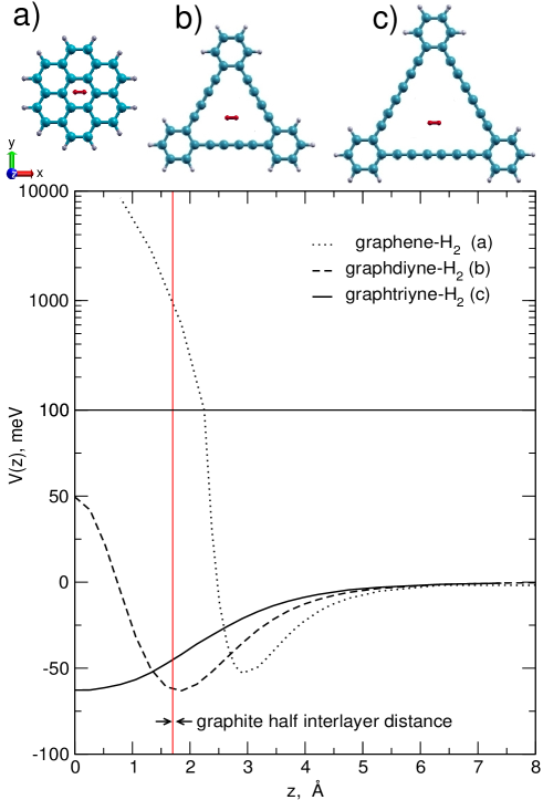
In the upper part of Fig. 1 we report the planar molecular structures that can be considered as the smallest precursorsBartolomei et al. (2013); Bartolomei et al. (2014a) of the graphene plane and of graphdiyine and graphtriyne pores and which are here used as prototypes to study their interaction with the H2 molecule, shown in red in the center of each structure. In particular the potential curves obtained at the MP2C level of theory and depicted in the lower part of Fig. 1 refer to the H2 molecule kept parallel to the molecular prototype planes and approaching their geometrical centers. The chosen relative configurations (sketched in the upper part of Fig. 1) are kept frozen during the calculations and are those providing for each case both the deepest interaction well and the lowest repulsive well at short distances. In the case of graphene the minimum is located at about 2.9 Å from the plane and the related well depth is about 53 meV. This findings are in very good agreement with previous experimentalVidali et al. (1991) and theoreticalRubes et al. (2010); Silvestrelli and Ambrosetti (2014) estimations. Moving from graphene to graphynes the corresponding well depth becomes deeper and closer to the carbon plane. In particular for both graphdiyne and graphtriyne a well depth of about 63 meV is obtained, while the minimum is found at 1.8 Å for the former and right in the plane for the latter. In order to qualitatively draw conclusions on the possibility of hydrogen intercalation a vertical line, corresponding to the graphite half interlayer distance (equals to 1.675 Å), is also depicted. At this distance the potential for graphene is already very repulsive (about 1000 meV) and this clearly confirms that the existence of molecular hydrogen inside graphite is not possible. Nevertheless in the case of the two graphynes a quite different scenario appears: for graphdiyne the minimum almost matches graphite half interlayer distance while for graphtriyne, even if the corresponding well is located at shorter distances, it is actually quite flat and around 1.7 Å the interaction potential is still attractive and around -50 meV. Moreover, the penetration barrier is extremely large for graphene, it becomes quite lower for graphdiyne, and it completely disappears for graphtriyne. Therefore from the results of Fig. 1 it can be inferred that for graphynes not only the adsorption energy seems to be more favourable than for graphene but also that hydrogen out-of-plane diffusion and intercalation could be possible in multi-layer graphynes.
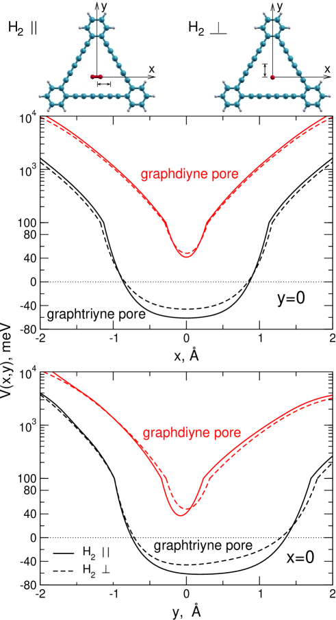
In order to further investigate these possibilities we have studied more in details the features of the H2–graphynes interaction by considering the hydrogen molecule right inside the graphynes’ pores. In fact, in Fig. 1 a low but non-negligible penetration barrier has been found for graphdiyne and a better description of its features, which can affect the diffusion of the hydrogen molecule through the pores, is desirable. In Fig. 2 the in-plane behavior of the H2–graphynes interaction is reported. In details, we show the interaction potential as a function of the displacement of the H2 molecule from the pore geometric center and along two main directions (see upper part of Fig. 2). First of all we notice that for both graphynes the potential does not depend dramatically on the orientation of the H2 molecule: if it is parallel to the pore plane (solid line) then it is slightly more attractive around the geometric center than the profile for the perpendicular configuration (dashed line); on the other hand the opposite occurs when the potential becomes repulsive, that is for displacements in general larger than 1 Å. This behaviour could be expected considering that the H2 molecule is almost spherical from the electronic structure point of view since both its quadrupole moment and dipole polarizability anisotropies are small Cappelletti et al. (2008). More importantly, a quite large interaction anisotropy is indeed found for graphdiyne when the H2 molecule is out of the geometric center: even for displacements as short as few angstrom tenths in both directions the potential is more than twice and then increase rapidly reaching very repulsive values of about 1000 meV at around 1 Å from the center. Therefore even if for graphdiyne the barrier for H2 passage through the pore apparently seems to be low it assumes indeed values below 50 meV just in a very reduced area of about 0.04 Å2 around its center. These findings suggest that the H2 diffusion through the graphidiyne pore is very unlikely at standard temperature and pressure. On the contrary, for graphtriyne the in-pore interaction anisotropy is quite lower: we can observe a flat well spreading in both coordinate directions and the potential remains attractive for displacements from the center as large as about 1 Å. These results suggest that for graphtriyne pores there is a large area (about 3 Å2) available for an unimpeded H2 passage; it follows that one hydrogen molecule can diffuse through the layer and be easily adsorbed in the pore. We can also infer that in principle if a further H2 is taken into account both of them can not coexist in the pore plane since the equilibrium distance (about 3.3 Å) for the H2 dimerDiep and Johnson (2000) is larger than the diameter of the area describing the attractive potential. Therefore on the basis of the results reported in Figs.1 and 2 we can conclude that graphtriyne sheets are better than graphdiyne ones to build up ideal carbon-based layered surfaces suitable for H2 physical adsorption; in fact, the pores of the former provide a large area featuring an attractive interaction potential which also extends out of the plane maintaining negative values lower than -30 meV even for distances as far as 2.5 Å from the layer.
III.2 Multi-layer structure and adsorption energies
In order to further investigate the possibility of hydrogen adsorption on graphtriyne surfaces the next convenient step has been to consider a multi-layer to assess whether intercalation is really energetically favorable or not. To do that we have considered a novel kind of graphite which is composed of stacked graphtriyne sheets instead of graphene layers; its actual 3D structure represents a critical point since it could occur that the interlayer distance is too short to allow the hydrogen molecules to be hosted and also that the pore of one layer is partially obstructed by benzenic rings of the adjacent layers.
The 3D arrangement of bulk graphyne and graphdiyne has been recently investigatedDecéré et al. (2013); Zhang et al. (2013); Luo et al. (2013) by means of periodic dispersion-corrected DFT calculations and it has been found that the corresponding interlayer equilibrium distance is likely largerZhang et al. (2013); Decéré et al. (2013) than that of graphite. Nevertheless we believe that the methodologies employed in these studies are not accurate enough to guarantee the reliability of the estimated 3D structure since the reported results in the case of pristine graphite, which is used as a benchmark test, showed that the related interlayer equilibrium distance is not correctly reproduced. Therefore our choice has been instead to employ for the graphtriyne multi-layers the approach very recently introduced by Brandenburg et al. Brandenburg et al. (2013) which provided accurate and reference values for both exfoliation energy and interlayer separation of graphite.
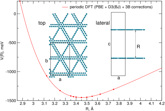
In particular we have considered at first a supercell containing an isolated graphtriyne bilayer (see Fig. 3) and we have assumed that its relative configuration is similar to that of the most stable Bernal stacking found in pristine graphite: benzene rings in different adjacent layers are displaced of 1.431 Å along one of the acetylenic chains joining two contiguous rings. This relative orientation corresponds to a minimum also in the case of bulk graphdiyneLuo et al. (2013) and it has been considered frozen throughout the DFT calculations whose results provided the cell energy as a function of the interlayer distance, as shown in Fig. 3. We have found that the equilibrium interlayer distance for the graphtriyne bilayer is 3.45 Å, which is just 0.1 Å larger than that for pristine graphite. This result could be understood considering that a graphtriyne plane contains a lower density of carbon atoms with respect to graphene and consequently the size of both attractive and repulsive contributions to the interlayer interaction is presumably reduced.
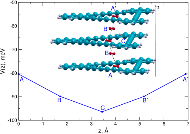
Once the structure of the graphtriyne bilayer has been determined we have used the related equilibrium geometry to build up a graphtriyne multilayer prototype. To do that we have considered three parallel graphtriyne pores in a Bernal-like stacking and with adjacent layers separated of 3.45 Å. The used prototype for the graphtriyne trilayer is reported in Fig. 4 and its choice is justified since its reduced size allows the application of the accurate but computationally expensive MP2C level of theory to determine the H2 adsorption energy. In Fig. 4 the positions of the H2 molecule considered for the calculations are also reported and they are indicated with A, B, C, B’ and A’ blue letters. In particular the A, A’ and C sites correspond to in-pore configurations in which the H2 molecule is right in the pore geometric center and parallel to the layers. B and B’ equivalent sites correspond instead to the H2 intercalation: the molecule center of mass lie right in the direction (dashed line) joining the geometric centers of adjacent pores and it is placed at 1.725 Å (half the interlayer distance) from the closest layers, with the diatom oriented parallel to them. The reported adsorption energies obtained at the MP2C level and shown in the lower part of Fig. 4 correspond to the sum of three contributions related to the H2 molecule interacting with each of the graphtriyne pore. It can be seen that for the in-pore A, A’ and C locations the obtained interaction energies are significantly larger than that for the single pore case (see Figs. 1 and 2): clearly the largest interaction correspond to the C case with the H2 molecule inside the intermediate pore and the related adsorption energy is about 96 meV. As for the B and B’ intercalation sites, the interaction energies are also very attractive, around -90 meV, even if slightly less than that for the C position. The obtained results for the C and B sites should be considered as reliable estimations of typical in-pore and intercalation interaction energies for H2 inside a periodic graphtriyne multi-layer and their large value, especially considering that only non-covalent interactions are involved, allow to suggest the following conclusions. The first point is that no impediment is present for H2 penetration across graphtryine multi-layers since it can pass from a pore to the adjacent one along the direction (see Fig. 4) without any barrier. This means that the out-of-plane diffusion through the novel porous graphite is feasible. Nevertheless it should be clarified that in-plane diffusion (i.e. along the directions perpendicular to ) is instead very unlikely for the inner layers since the interaction energy becomes very repulsive when H2 is close to the carbon atoms (see Fig. 2 and Fig. S1 of the Supplementary Material). The second point to highlight is that the quite favourable interaction energies imply that this novel porous carbon material could be used for hydrogen reversible storage.
On the basis of present results we can safely conclude that at least one hydrogen molecule could be stored per graphtriyne pore; if we consider the periodic cell reported in Fig. 3 we can qualitatively estimate gravimetric and volumetric capacities of about 1.4 wt% and 0.015 kg/L-1, respectively. Even if these predictions are comparable with the best hydrogen uptakes obtained so far for other carbon nanostructuresPanella et al. (2005); Klechikov et al. (2015) at room temperature, they are however somehow far from the best target proposed by the DOEDOE . Still, by taking into account that intercalation is also possible, we expect that more than one hydrogen molecules could accommodate themselves above and below each pore. As an example, if we assume that three H2 molecules can coexist between the parallel openings we could reach gravimetric and volumetric capacities of about 4 wt% and 0.046 kg/L-1, respectively, which are in the range or even beyond the wanted storage limitsDOE .
IV Conclusions
In summary, by means of electronic structure computations, we have shown that graphynes are more suited than graphene for the physical adsorption of H2. As a matter of fact the adsorption energy on a single layer is larger on graphynes and the H2 equilibrium distance is closer to the carbon plane. The features of the considered graphynes pores have been further investigated and we have demonstrated that for graphdiyne the in-pore interaction is repulsive and represents a high impediment to H2 crossing; on the contrary for graphtriyne the in-pore interaction is attractive and a flat minimum is found. On the basis of these results a novel type of graphite, composed of graphtriyne stacked layers, is proposed and its structure is determined. By performing calculations of the interaction energy for the graphtriyne multi-layer we have found that the H2 molecule can freely diffuse in the direction perpendicular to the carbon sheets and that in-pore and intercalation sites provide very favourable adsorption energies in the range of 0.1 eV.
Present data provide reliable benchmark results that can be used to tune-up a new force field suitable to perform dynamical simulations capable to correctly assess the actual H2 uptake of this novel material. Work in this direction is in progress.
The proposed porous graphite could be considered as a promising alternative to more traditional adsorbing materials such as zeolites and MOF; in fact it shares with them a cristallyne structure with regular pores of well defined size but with the vantage points of being in principles lighter, chemically inert and thermally stable. Hopefully theoretical investigations on this topic can further stimulate the progress in the synthesis of large pore graphynes such as graphtriyne, the building block of the porous graphite here introduced.
Acknowledgments
The work has been funded by the Spanish grant FIS2013-48275-C2-1-P. Allocation of computing time by CESGA (Spain) is also acknowledged.
Supplementary Material
Intermolecular potentials related to different configurations used for graphtriyne pore–H2 computations are reported in an additional figure. This information is available free of charge via the Internet.
References
- Züttel (2004) A. Züttel, Naturwissenschafen 91, 157 (2004).
- (2) See Executive Summaries for the Hydrogen Storage Materials Centers of Excellence, http://www1.eere.energy.gov/hydrogenandfuelcells/pdfs/executive_summaries_h2_storage_coes.pdf. See also Hydrogen Storage Overview (2012 Annual Merit Review and Peer Evaluation Meeting of U.S. DOE ), http://www.hydrogen.energy.gov/pdfs/review12/st000_stetson_2012_o.pdf.
- Broom and Thomas (2013) D. P. Broom and K. M. Thomas, MRS Bullettin 38, 412 (2013).
- Makal et al. (2012) T. A. Makal, J. R. Li, W. Lu, and H. C. Zhou, Chem. Soc. Rev. 41, 7761 (2012).
- Bieri et al. (2009) M. Bieri, M. Treier, J. Cai, K. Aït-Mansour, P. Ruffieux, O. Gröning, P. Gröning, M. Kastler, R. Rieger, X. Feng, et al., Chem. Commun. 45, 6919 (2009).
- Li et al. (2010) G. Li, Y. Li, H. Liu, Y. Guo, Y. Li, and D. Zhu, Chem. Commun. 46, 3256 (2010).
- Narita et al. (1999) N. Narita, S. Nagai, S. Suzuki, and K. Nakao, Phys. Rev. B 58, 11009 (1999).
- Cranford and Buehler (2012) S. W. Cranford and M. J. Buehler, Nanoscale 4, 4587 (2012).
- Lin and Buehler (2013) S. Lin and M. J. Buehler, Nanoscale 5, 11801 (2013).
- Bartolomei et al. (2014a) M. Bartolomei, E. Carmona-Novillo, M. I. Hernández, J. Campos-Martínez, F. Pirani, G. Giorgi, and K. Yamashita, J. Phys. Chem. Lett. 5, 751 (2014a).
- Bartolomei et al. (2014b) M. Bartolomei, E. Carmona-Novillo, M. I. Hernández, J. Campos-Martínez, F. Pirani, and G. Giorgi, J. Phys. Chem. C 118, 29966 (2014b).
- Patchkovskii et al. (2005) S. Patchkovskii, J. S. Tse, S. N. Yurchenko, L. Zhechkov, T. Heine, and G. Seifert, Proc. Nati. Acad. Sci., USA 102, 10439 (2005).
- Cabria et al. (2008) I. Cabria, M. J. López, and J. A. Alonso, Phys. Rev. B 78, 075415 (2008).
- Vidali et al. (1991) G. Vidali, G. Ihm, H. Y. Kim, and M. W. Cole, Surf. Sci. Rep. 12, 133 (1991).
- Rubes et al. (2010) M. Rubes, J. Kysilka, P. Nachtigall, and O. Bludsky, Phys. Chem. Chem. Phys. 12, 6438 (2010).
- Silvestrelli and Ambrosetti (2014) P. L. Silvestrelli and A. Ambrosetti, J. Chem. Phys. 140, 124107 (2014).
- Jiao et al. (2011) Y. Jiao, A. Du, M. Hankel, Z. Zhu, V. Rudolph, and S. C. Smith, Chem. Commun. 47, 11843 (2011).
- Zhang et al. (2013) H. Zhang, X. Zhao, M. Zhang, Y. Luo, G. Li, and M. Zhao, J. Phys. D: Appl. Phys. 46, 495307 (2013).
- Hesselmann and Korona (2011) A. Hesselmann and T. Korona, Phys. Chem. Chem. Phys. 13, 732 (2011).
- Bartolomei et al. (2013) M. Bartolomei, E. Carmona-Novillo, M. I. Hernández, J. Campos-Martínez, and F. Pirani, J. Phys. Chem. C 117, 10512 (2013).
- Pitonák and Hesselmann (2010) M. Pitonák and A. Hesselmann, J. Chem. Theory Comput. 6, 168 (2010).
- Werner et al. (2012) H.-J. Werner, P. J. Knowles, R. Lindh, F. R. Manby, M. Schütz, P. Celani, T. Korona, G. Rauhut, R. D. Amos, A. Bernhardsson, et al., Molpro, version2012.1, a package of ab initio programs (2012), seehttp://www.molpro.net.
- Pei (2012) Y. Pei, Physica B 407, 4436 (2012).
- Kendall et al. (1992) R. A. Kendall, T. H. Dunning, and R. J. Harrison, J. Chem. Phys. 96, 6796 (1992).
- Boys and Bernardi (1970) S. Boys and F. Bernardi, Mol. Phys. 19, 553 (1970).
- Kresse and Furthmüller (1996) G. Kresse and J. Furthmüller, Phys. Rev. B 54, 11169 (1996).
- Perdew et al. (1996) J. Perdew, K. Burke, and M. Ernzerhof, Phys. Rev. Lett. 77, 3865 (1996).
- Blöchl (1994) P. Blöchl, Phys. Rev. B 50, 17953 (1994).
- Kresse and Joubert (1999) G. Kresse and D. Joubert, Phys. Rev. B 59, 1758 (1999).
- Grimme et al. (2011) S. Grimme, S. Ehrlich, and L. Goerigk, J. Comput. Chem. 32, 1456 (2011).
- Brandenburg et al. (2014) J. G. Brandenburg, M. Hochheim, T. Bredow, and S. Grimme, J. Phys. Chem. Lett. 5, 4275 (2014).
- Grimme et al. (2010) S. Grimme, J. Antony, S. Ehrlich, and H. Krieg, J. Chem. Phys. 132, 154104 (2010).
- Cappelletti et al. (2008) D. Cappelletti, F. Pirani, B. Bussery-Honvault, L. Gómez, and M. Bartolomei, Phys. Chem. Chem. Phys 10, 4281 (2008).
- Diep and Johnson (2000) P. Diep and J. K. Johnson, J. Chem. Phys. 112, 4465 (2000).
- Decéré et al. (2013) J. Decéré, C. Lepetit, and R. Chauvin, J. Phys. Chem. C 117, 21671 (2013).
- Luo et al. (2013) G. Luo, Q. Zheng, W. Mei, J. Lu, and S. Nagase, J. Phys. Chem. C 117, 13072 (2013).
- Brandenburg et al. (2013) J. G. Brandenburg, M. Alessio, B. Civalleri, M. F. Peintinger, T. Bredow, and S. Grimme, J. Phys. Chem. A 117, 9282 (2013).
- Panella et al. (2005) B. Panella, M. Hirscher, and S. Roth, Carbon 43, 2209 (2005).
- Klechikov et al. (2015) A. G. Klechikov, G. Mercier, P. Merino, S. Blanco, C. Merino, and A. V. Talyzin, Micropor. Mesopor. Mater. 210, 46 (2015).