Nanostructures imaging via numerical solution of a 3-d inverse scattering problem without the phase information 111The work of first two authors was supported by the office of Naval Research grant N00014-15-1-2330 and the US Army Research Laboratory and US Army Research Office grant W911NF-15-1-0233.
Abstract
Inverse scattering problems without the phase information arise in imaging of nanostructures whose sizes are hundreds of nanometers as well as in imaging of biological cells. The governing equation is the 3-d generalized Helmholtz equation with the unknown coefficient, which represents the spatially distributed dielectric constant. It is assumed that only the modulus of the complex valued wave field is measured on a frequency range. The phase is not measured. Two rigorous numerical methods are tested and their performances are compared for realistic ranges of parameters. These methods are based on two reconstruction procedures, which were recently proposed in [21, 22].
35R30, 35L05, 78A46
Keywords: Phaseless inverse scattering problem, imaging of nanostructures and biological cells, rigorous numerical methods .
1 Introduction
This is the first publication in which rigorous numerical methods are applied to solve the phaseless inverse scattering problem of the reconstruction of a coefficient of a PDE. We also mention the work of Ivanyshyn, Kress and Serranho [11] as well as that of Ivanishin and Kress [12], in which surfaces of obstacles are numerically reconstructed from the phaseless data.
Inverse scattering problems without the phase information occur in imaging of structures whose sizes are of the micron range or less. Recall that 1 micron ( For example, nano structures typically have sizes of hundreds on nanometers (nm). Either optical of X-ray radiation is used in this imaging. Since the sizes of these nanostuctures are between and Therefore, the wavelength for this imaging should be approximately in the range Another example is in imaging of living biological cells. Sizes of cells are between and [32, 33]. It is well known that for the micron range of wavelengths only the intensity of the scattered wave field can be measured, and the phase cannot be measured [7, 8, 14, 31, 38]. Here, the intensity is the square modulus of the scattered complex valued wave field.
In the standard inverse scattering problem in the frequency domain, one is supposed to determine a scatterer given measurements of the complex valued wave field on the boundary of the domain of interest, see, e.g. [9, 10, 25, 27, 28]. Unlike this, in the current paper we reconstruct scatterers when only the modulus of that wave field is available while the phase is unknown.
As to the uniqueness question of phaseless inverse scattering problems, the first uniqueness theorem was proven by Klibanov and Sacks in the 1-d case [15]. Also, see the work of Aktosun and Sacks [1] for a follow up result. Next, uniqueness in the 3-d case was established by Klibanov in [16, 17, 18]. However, proofs in these references are not constructive ones. This prompted Klibanov and Romanov to work on reconstruction procedures [19, 20, 21, 22, 23]. We also refer to two reconstruction procedures for phaseless inverse scattering problems which were recently developed by Novikov [29, 30]. Procedures of [29, 30] are quite different from ones of [19, 20, 21, 22, 23].
We compare here performances of two numerical methods. The first one is based on the Born approximation, as proposed in [21], when the wave field is governed by a linearization of the generalized Helmholtz equation at the standard one. However, this approximation fails for large values of the frequency which are actually used both in [21] and in this paper. Because of this, Klibanov and Romanov have proposed the second linearization idea, which does not fail for large values of [22]. Furthermore, the linearization in this case is done only on the last step: to solve the so-called Inverse Kinematic Problem, whereas the phase is recovered without a linearization. Indeed, even though the Inverse Kinematic Problem is investigated quite well by now, see, e.g. books [24, 35, 36], it is yet unclear how to solve it numerically without the linearization.
So, our second method is based on the reconstruction procedure of [22]. Still, we have a significantly new element here, compared with [22], see subsection 4.3. While the case of the point sources was considered in [22], in [23] the case of incident plane waves was considered. Two other reconstruction procedures, which are suitable for a simpler case of the Schrödinger equation, were developed by Klibanov and Romanov in [19, 20].
In all five above listed reconstruction procedures of [19, 20, 21, 22, 23], as well as in this paper, the last step is the well known inverse Radon transform, see, e.g. the book of Natterer [26] about this transform. And in all five this transform should be applied only in the limiting case of We, however, work with specific values of the dimensionless frequency which occur in imaging of nanostructures and biological cells, see Section 2 for our values of . Therefore, it is not immediately clear whether some good results can be obtained for these practically acceptable values of if using the techniques of [21, 22].
In Section 2, we pose the inverse problems we consider in this paper. In section 3 we briefly discuss the Lippmann-Schwinger equation, which we use to generate the data for inverse problems. In Section 4 we explain how do we solve our inverse problems numerically. In section 5 we present numerical results. Section 6 is devoted to a discussion of our results.
2 Problem settings
Let be a bounded domain. Let be the ball of the radius with the center at We assume that Denote Let be a real valued function satisfying the following conditions
| (2.1) | ||||
| (2.2) | ||||
| (2.3) |
The smoothness requirement imposed on the function is clarified in the proof of Theorem 1 of [22]. The non-negativity of the function in (2.3) is due to the fact that the function is the spatially distributed dielectric constant in the above mentioned applications. In other words in the medium of our interest, the dielectric constant exceeds the one of the vacuum. The function generates the conformal Riemannian metric as
| (2.4) |
Here is the assumption which we use everywhere below:
Assumption 1.
We assume that geodesic lines of the metric (2.4) satisfy the regularity condition, i.e. for each two points , there exists a single geodesic line connecting them.
For let be the solution of the eikonal equation,
| (2.5) |
Here and below all derivatives are with respect to components of the vector Let be the euclidean arc length of the geodesic line Then [36, 37]
| (2.6) |
Hence, is the travel time between points and due to the Riemannian metric (2.4). Due to Assumption 1, is a single-valued function of both points and in .
Consider the equation
| (2.7) |
where the frequency where is the wavelength. We now comment on the ranges of parameters used in our computations below. We point out that we work with ranges of parameters which are realistic to the applications to imaging of nanostructures of several hundreds nanometers size as well as of living biological cells. The range of our wavelengths is
| (2.8) |
Thus, in our computations is the sphere of the radius Let us make variables to be dimensionless in (2.7). To do so, introduce a new variable while keeping the same notations as above for brevity. Then elementary operations show that equation (2.7) remains the same. Recall that the frequency Hence, we obtain that the dimensionless frequency ,
| (2.9) |
Thus, below all functions, parameters and variables are dimensionless. The single non-realistic parameter in our computations is the assumption that one can conduct real measurements on the sphere of such a small radius as In fact, usually such measurements are conducted on the surface of a sphere of several centimeters size [8]. This is a delicate issue which will be considered in our future works.
To introduce the point source in equation (2.7), we modify it as
| (2.10) |
where is the source position. We assume that the function satisfies the radiation condition,
| (2.11) |
Denote the solution of the problem (2.10), (2.11) for the case Then is the incident spherical wave,
Let be the scattered wave, which is due to the presence of scatterers, in which . Then
| (2.12) |
It was shown in [22] that problem (2.10), (2.11) has unique solution . Moreover, is in for any and Here is the Hölder space.
We model the propagation of the electric wave field in by a single equation (2.10) with the radiation condition (2.11) instead of the full Maxwell’s system. This modeling was numerically justified in the work of Beilina [5] in the case of the Cauchy problem for the equation . It was established in [22] that, given Assumption 1, the solution of the problem (2.10), (2.11) is the Fourier transform of the function with respect to . It was demonstrated in [5] that the component of the electric wave field, which is incident upon the medium, significantly dominates two other components when propagating through the medium. Furthermore, the propagation of that dominating component is well governed by the function . This conclusion was verified via accurate imaging using electromagnetic experimental data in, e.g. Chapter 5 of the book of Beilina and Klibanov [2] and in [3, 4, 40, 41]. In those experimental data only the single component of the scattered electric wave field was measured: the one which was originally incident upon the medium. We believe that the confirmation on the experimental data has a significant merit.
Along with the function we consider its Born approximation. The Born approximation assumes that the resolvent series for the Lippmann-Schwinger integral equation (section 3) converges. Next, it considers only the first term in this series and truncates the rest of terms. In other words, it is assumed that [21]
| (2.13) |
Note that the the Born approximation breaks up for large values of .
In this paper we study the following two inverse problems:
Problem 1. Suppose that the following function is known
| (2.14) |
for a certain interval Suppose that the function satisfies conditions (2.1)-(2.3). Determine the function
Problem 2. Approximate the right hand side of (2.14) as
Let the given function be the same as in (2.14). Assume that
| (2.15) |
for some values of . Suppose that the function satisfies conditions (2.1)-(2.3). Determine the function
Remark 1.
- 1.
- 2.
3 Lippmann-Schwinger equation and the forward problem
To generate the function in (2.14), (2.15) for our numerical studies, we need to solve the forward problem (2.10), (2.11). In this section we briefly explain how we solve it via the solution of the Lippmann-Schwinger integral equation. Since in our numerical experiments the function only within small inclusions inside of the domain computations via the Lippmann-Schwinger equation are fast. Recall that by (2.12)
It follows from (2.10), (2.11) that satisfies
| (3.1) |
Using Theorem 8.3 in the book of Colton and Kress [6], we derive from (3.1) the Lippmann-Schwinger equation
| (3.2) |
Therefore, the integral equation for the total field is
| (3.3) |
Theorems 8.3 and 8.7 of [6] guarantee that there exists unique solution of the integral equation (3.3). Furthermore, this function is the solution of problem (2.10), (2.11) and, therefore, it has a higher smoothness (section 2). In our computations of the forward problem for data generation, we solve equation (3.3) for a discrete set of frequencies , for and for As soon as the function is found for its values for point can be easily found by substituting these points in the right hand side of (3.3). This solution produces the function which is the data for the above Problems 1 and 2.
4 Inverse Problems
4.1 Two main theorems
Our reconstruction methods are based on Theorems 1 and 2. Following [22], let , be geodesic coordinates of a variable point with respect to a fixed point in the above Riemannian metric (2.4). By Assumption 1, there exists a one-to-one correspondence for any fixed point . Therefore, for any fixed point the function has the inverse function The function determines the geodesic line
where is the vector which is tangent to at the point , is directed towards the point and also .
Consider the Jacobian The mapping is one-to-one and continuously differentiable. Still, this does not imply that for all It was established in [22] that Thus, we use everywhere below the following assumption:
Assumption 2.
for all
Define now the function as
| (4.1) |
Theorem 1 ([22]).
Combining this theorem with (2.12), we obtain the following asymptotic behavior of the function for as
| (4.3) |
To solve numerically Problem 2, we use Theorem 2.
Theorem 2 ([21]).
In the next two subsections, we discuss numerical methods of solutions of Problems 1, 2. We point out that since both numerical methods end up with the inversion of the 2D Radon transform, we are interested in imaging only a 2D cross-section of the function To do this, it is not necessary to measure the function in (2.14) and (2.15) for all Rather, it is sufficient to measure it for a corresponding 2D cross-section of the sphere i.e. for for a Without further mentioning we reconstruct images below only in the central 2D cross-section of the ball i.e. in the plane. We denote this cross-section as Thus, everywhere below “Radon transform” means the 2D Radon transform and means the function
4.2 Radon transform and Problem 2
One of the main tools of the numerical reconstruction of the function is the 2D Radon transform. In our computations we compute the inverse Radon transform using a tool box of MATLAB. For every real valued function , the Radon transform of , suggested by MATLAB, is given by
for The function above is just the integral along the line Here, is the line obtained by rotating the line in the plane around the origin by the angle For convenience, we name as the Radon coordinate of the line Denote the inverse Radon transform.
Consider now the Born approximation. It follows from Theorem 2 that
| (4.5) |
where
| (4.6) |
where is the Radon coordinate of the line for . The function approximates the Radon transform of the function when the pair This leads to the following reconstruction formula:
| (4.7) |
where the function is defined in (2.15) and is sufficiently large. Thus, formula (4.7) provides an approximate solution of Problem 2. In our results displayed in Section 5, .
4.3 Problem 1
We now study Problem 1. We develop in this subsection a new method of the recovery of functions and for from (4.3). This method is significantly different from the one proposed in [22]. This difference is caused by the fact that [22] is essentially using the assumptions that the frequency interval is sufficiently large. However, by (2.9) our the realistic range of dimensionless frequencies is Following [22], we ignore the term in (4.3). Hence, the function now is:
| (4.8) |
where
| (4.9) | ||||
| (4.10) | ||||
| (4.11) |
We now propose a stable method to extract the unknown quantities and from . Fix . For each define
For the simplicity of notations, we can temporarily ignore the dependence on of these functions. Assuming that , we obtain
| (4.12) | ||||
| (4.13) |
It follows from (4.8) and (4.13) that
| (4.14) |
Consider
as an unknown vector. We now should solve equation (4.14) with respect to the vector We are doing this via minimizing the following functional
Since equation (4.14) is linear with respect to the vector this functional can be minimized via setting to zero its first derivatives with respect to the components of the vector , assuming that the resulting matrix is not singular. Hence, a simple calculation yields that solves where
and
Remark 2.
In our computations presented in Section 5, the vector is calculated by solving
where is the transpose of and is a sufficiently small number.
Remark 3.
Recall that depends on . The function
is the phase we need to reconstruct. Having , we solve the quadratic equation (4.3) for . Note that this quantity might depend on and we need to take their average.
To verify the accuracy of the reconstructed functions for we compare them with those of the total field calculated via the numerical solution of equation (3.3). By (4.2) Since the right hand side of this equality depends on , we assign an approximate value of as
| (4.15) |
By (4.2) we have the following approximate formula at
Multiplying the equations above by and integrating the resulting equation over the interval we obtain
| (4.16) |
which yields an approximation of
Remark 4.
Remark 5.
Note that we have approximately found both functions and for without any linearization. However, it is unclear how to find the target function using these functions. Therefore, following [22], we linearize the problem below.
Thus, we have found the function for all The determination of the function from the function given for all is called “Inverse Kinematic Problem”. As it was stated in Introduction, it is yet unclear how to solve this problem numerically. Therefore, we solve below the linearized Inverse Kinematic Problem. Assume that We now linearize the function with respect to the function This linearization can be found in Theorem 11 of Chapter 3 of [24], in §5 of Chapter 2 of [35] and in §4 of Chapter 3 of [36]. We obtain
| (4.17) |
To be precise, one should have “” instead of “” in (4.17). Using (4.17), we obtain
| (4.18) |
Remark 6.
In the case that the line passes a scatterer, we call a forward scattering wave. If there is no inclusion on the line , is called either side or back scattering wave. We have observed in our computations that forward scattering waves dominate the side and back ones. We believe that this is the main reason why the inverse Radon transform, which is actually based on an analysis of projections, provides good quality images even though we work with the propagation of waves. Therefore, due to (4.17) and the reconstruction method in (4.18), we only find when
for some sufficiently small positive number (in our computation ). Otherwise, we set . This truncation enhances the resolution of the images, see item (j) in our Figures.
5 Numerical results
In the section the domain . Hence, in this section The domain is the cube inscribed in and sides of this cube are parallel to coordinate planes. Since by (2.3) the function outside of this cube then images below are presented only in the central 2D cross section of i.e. in the square The range of dimensional frequencies is as in (2.9). Recall that by (2.8) this means that wavelengths Due to the smoothness requirements imposed on the function in Theorems 1, 2, we introduce the shape function as:
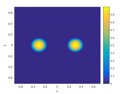
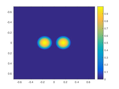
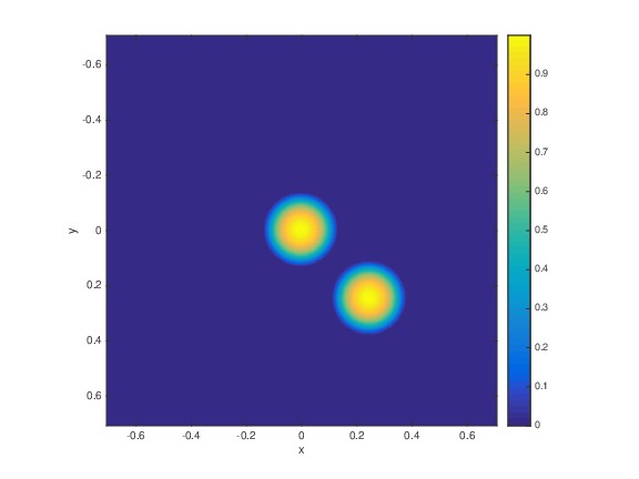
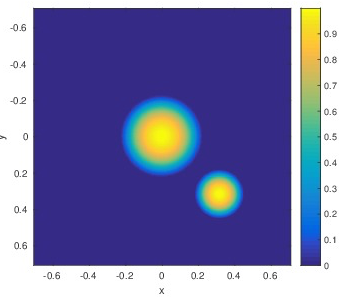
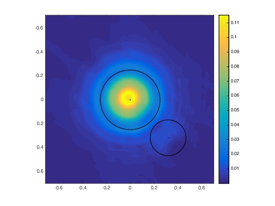
to construct some true models based on Here is how we construct each inclusion. First, we consider a ball of the radius with the center at the point . And we set the initial function as inside this inclusion and outside of it. Here Next, we set Hence, is the maximal value of the function in that inclusion. If we have two inclusions, we act similarly. Below the “distance between surfaces of two inclusions” means the distance between surfaces of those two original spheres and the “radius” of an inclusion means the radius of that original sphere. Clearly the number can be considered as the inclusion/background contrast of the function In all our numerical examples
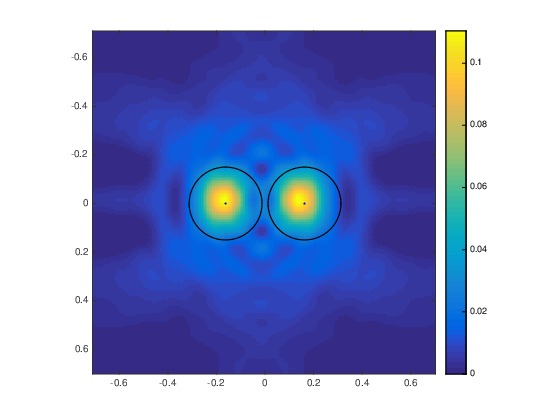
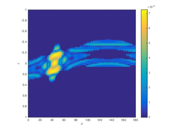
In this section, we show numerical results in several cases. For each case we show results as solutions of both problems 1 and 2. In the case of Problem 2 we use two values of In particular, we want to evaluate the resolution of our technique. We define the resolution as the distance between surfaces of two inclusions at which they can be separated in our images. Even though distances below are dimensionless, dimensions can be easily assigned: the dimensionless distance means microns. Thus, our cases are:
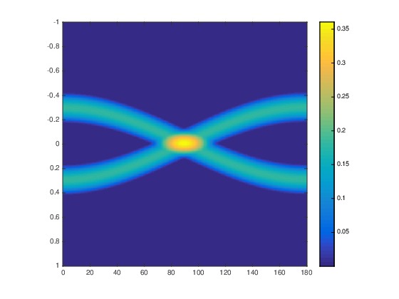
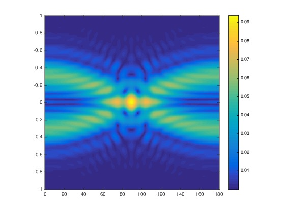
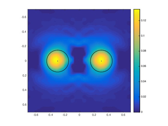
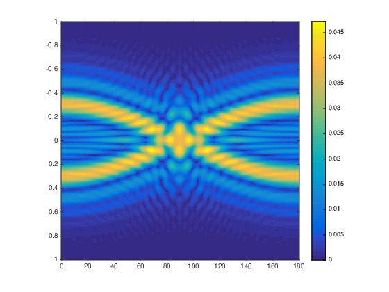
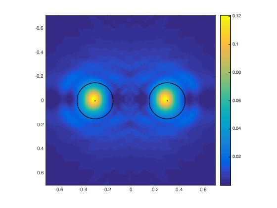
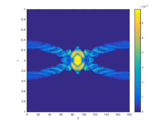
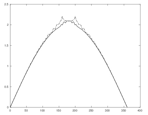
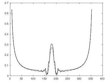
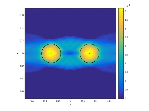
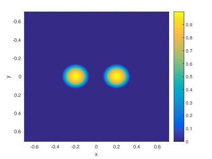
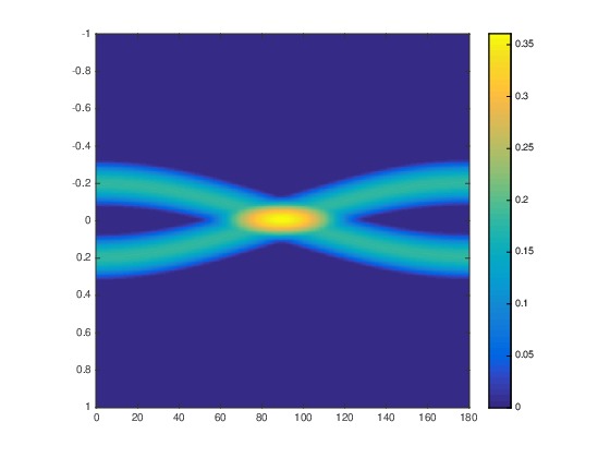
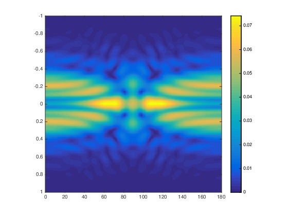
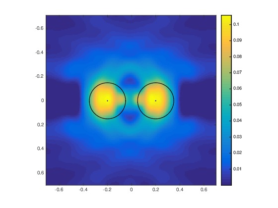
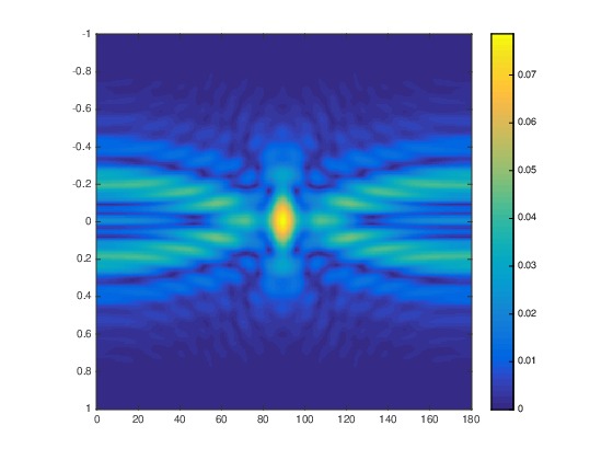
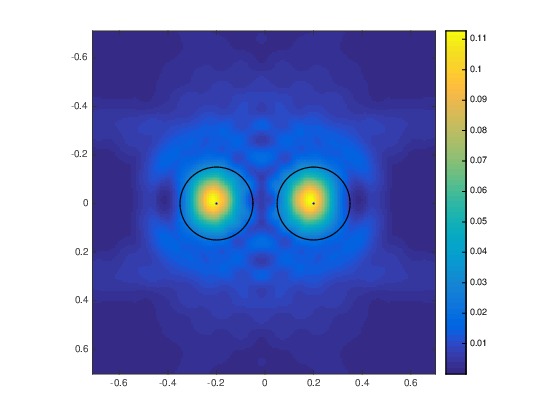
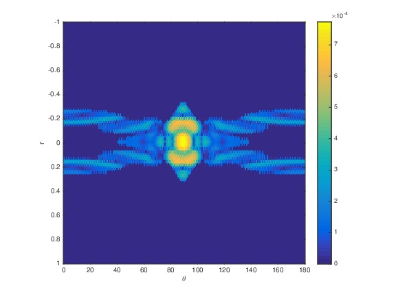
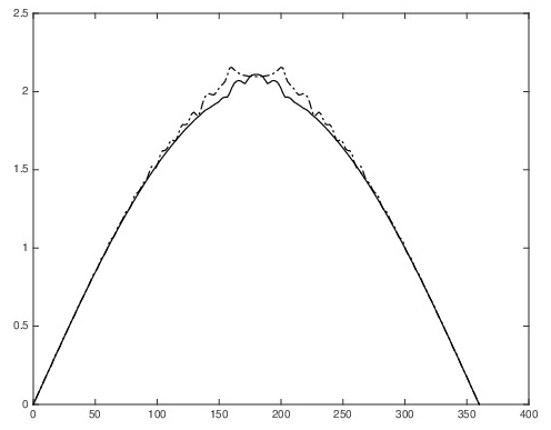
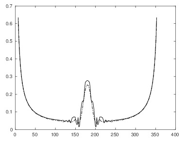
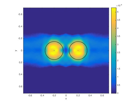
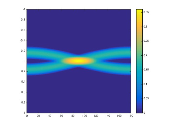
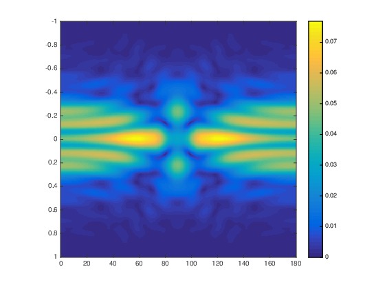
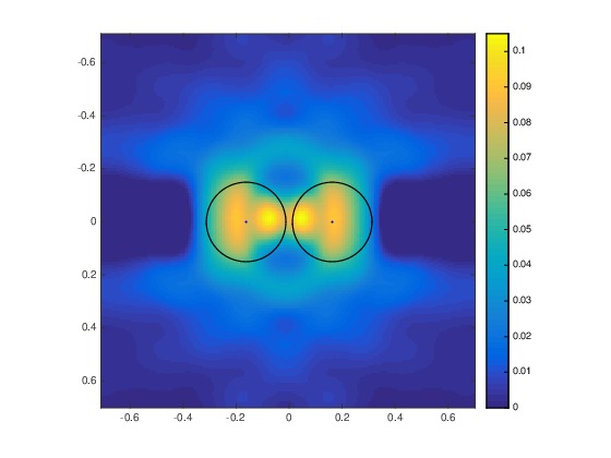
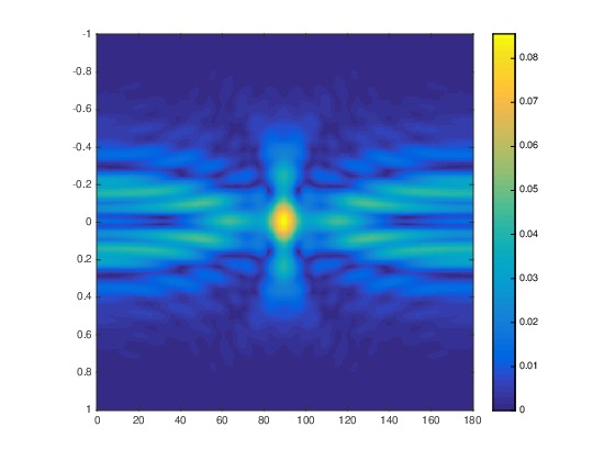
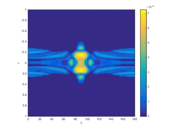
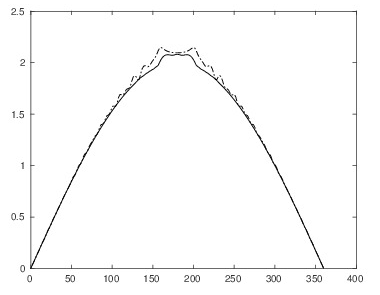
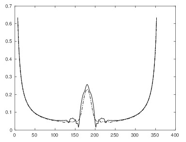
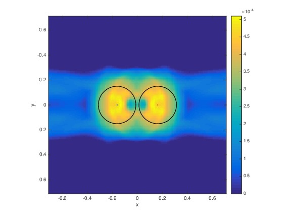
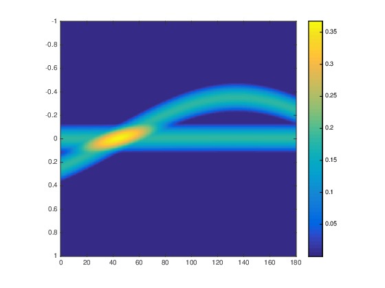
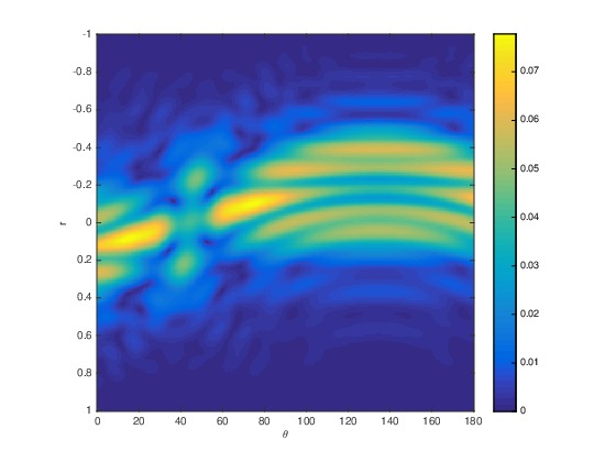
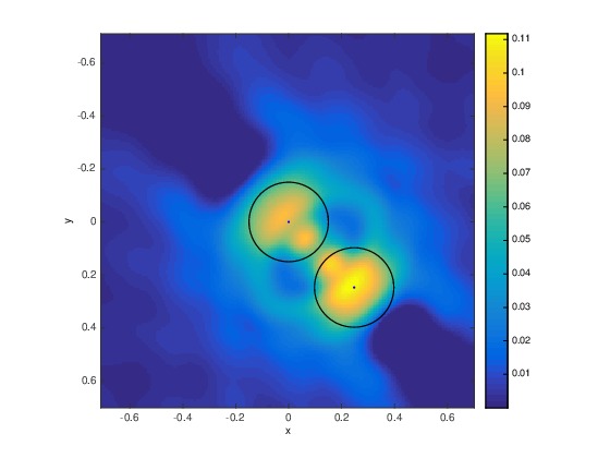
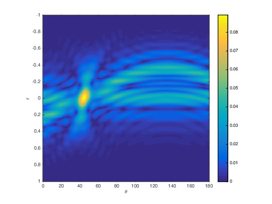
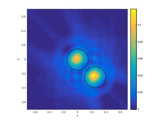
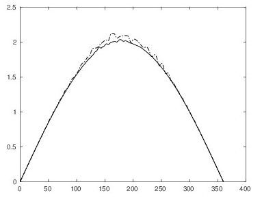
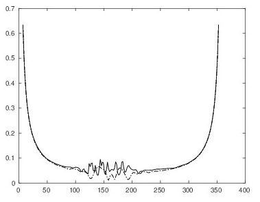
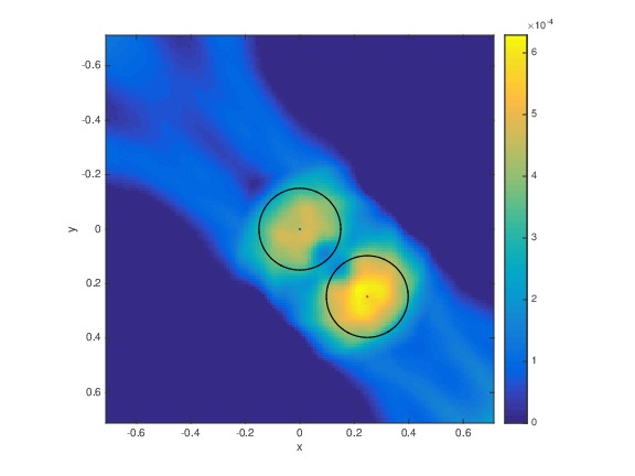
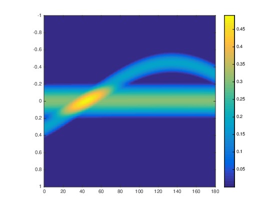
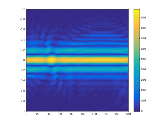
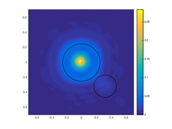
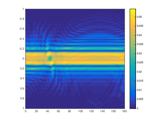
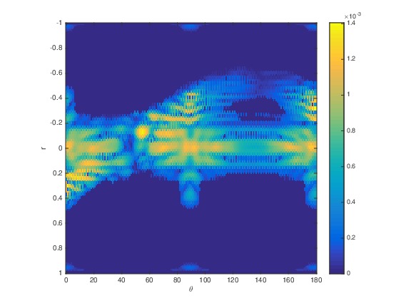
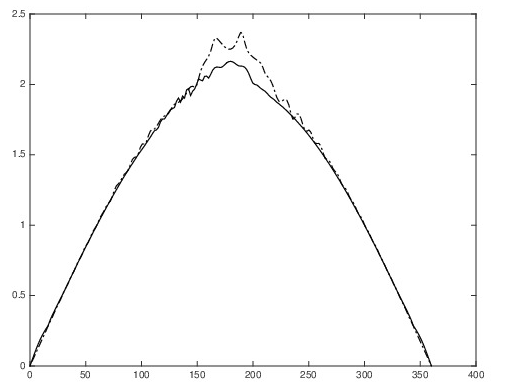
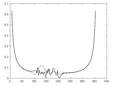
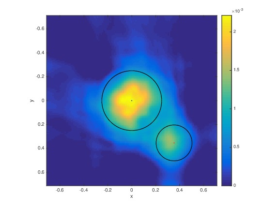
In each Figure, the square has the center at and its side equals Hence, this square is inscribed in the circle of the radius with the center at the origin. We display in each figure: (a) the 2D cross-section in the plane of the true image, (b) the Radon transform of the true function (c) The function (d) The reconstructed image (e) The function (f) The reconstructed image (g) the reconstructed function for in coordinates, (h) The approximate (Remark 4) and reconstructed phases when the point runs along the bottom side of the square and the source (i) The approximate (Remark 4) and reconstructed moduli of the total field for the same as in (h), (j) The reconstructed image via the solution of Problem 1 (subsection 4.3).
We have applied a postprocessing procedure to our images. For each vertex we found a disk with the center at of the radius . Then we have calculated the average value of the imaged function over all vertices inside of Next, we prescribed that average value as the value of at the vertex . Next, since by (2.3) , we truncated to zero all negative values of the resulting function Our images display functions obtained after this procedure.
It is worth mentioning the software Armadillo by Sanderson [39]. It involves a linear algebra package which is very helpful to speed up our computations.
6 Summary
In this paper, two rigorous numerical reconstruction procedures are applied for the first time to solve the 3D inverse scattering problem without the phase information for the generalized Helmholtz equation (2.10). We have conducted our computations for ranges of parameters, which are realistic for applications to imaging of nanostructures of hundreds of nanometers size. Both X-rays and optical signals on the wavelengths range (2.8) can be used as sources of radiation. Imaging of living biological cells using optical signals is also feasible.
We have used two reconstruction procedures. The first one is based on the idea of [22]. Here, the specific way of finding the travel time for is significantly different from the one proposed in [22]. This is because it is assumed in [22] that a large interval of frequencies is available. However, by (2.9) our realistic dimensionless frequencies deviate, as the maximum, by 30% () from the central frequency . The second reconstruction procedure is based on the Born approximation assumption of [21] and it is simpler than the one of [22].
In both procedures the linearization takes place. While the Born approximation assumes the linearization from the start, the procedure of [22] uses the linearization only on the last step: after the function for is found. The linearization in this case is caused by the fact that it is yet unclear how to compute numerically the function see, e.g. books [24, 35, 36] if the travel time is known for
Each of our two methods actually assumes that the frequency and ends up with the 2D Radon transform. Even though one should work, in principle at least, with infinite values of , we demonstrate good quality images for our realistic values of . Furthermore, even though the Born approximation becomes invalid for large values of , our computations show that images, using the Born approximation, are slightly better for than for . This is regardless on the fact that in both cases the data for the inverse problem were generated via the solution of the corresponding forward problem (3.3) without the Born approximation assumption. The qualities of images are about the same for both methods. Still, in the case of Figure 3 the image provided by the solution of Problem 1 has a better quality than the one provided by the Born approximation.
By (2.8) the minimal wavelength we use is On the other hand, we observe on Figure 3 that two inclusions with the distance of are resolved. Since then we observe a rare case of the super resolution. Another interesting observation for all our figures 1-5 is that our data are quite far from the range of the operator of the Radon transform: on each of Figures 1-5 compare (b) with (e) and (g). Nevertheless, the application of the inverse Radon transform to our data leads to rather good quality images. Although we have not added a random noise to our data, this difference in the data can also be considered as a noise in the data.
There is a significant advantage of the method of Problem 1 over the method of Problem 2. Indeed, the method of Problem 1 finds the phase as well as the modulus of the wave field for and for large with a good accuracy and without any linearization, see (h) and (i) in each of Figures 1-5 as well as (4.2). This should pave the way to a future significant image refinement. Indeed, while we image shapes of abnormalities with a good accuracy, the accuracies of the calculated abnormalities/background contrasts are poor. We attribute the latter to the linearization. On the other hand, as soon as the function is found accurately for one can apply a modified globally convergent method of [2] for a corresponding Coefficient Inverse Problem. The modification is due to the fact that in [2] the time domain data were considered and then the Laplace transform was applied. Whereas here we would need to have Fourier transform. An important point to make here is that the method of [2] images inclusions/background contrasts accurately.
Hence, one can apply a two-stage numerical procedure. On the first stage one would reconstruct the function for and for large values of . On this stage shapes of abnormalities will be well reconstructed. On the second stage one would reconstruct the function within abnormalities, while keeping the shape the same as it was obtained on the first stage. On the second stage, one would use the already calculated approximation for the function to find the first approximation for the so-called “tail function”. This function is an important element of the method of [2].
We note that this is a sort of a reversed two-stage procedure of Chapters 4 and 5 of [2]. In [2] the globally convergent method is applied on the first stage to find locations of abnormalities and inclusions/background contrasts. On the second stage, a sequence of Tikhonov functionals is minimized in the so-called “adaptivity technique” to find the shapes of inclusions. In doing so, the solution of the first stage is used as the starting point of iterations. It is important that the method of [2] is completely verified on experimental data, see Chapter 5 of [2] as well as [3, 4, 40, 41]. The second option for the globally convergent method is the one of [13], where a globally convex cost functional is constructed using a Carleman Weight Function. In both these globally convergent methods only one source position at a time is used. This means in our case that we can use several sources sequentially to refine the images further.
References
- [1] T. Aktosun and P.E. Sacks, Inverse problem on the line without phase information, Inverse Problems, 14 (1998) 211-224.
- [2] L. Beilina and M.V. Klibanov, Approximate Global Convergence and Adaptivity for Coefficient Inverse Problems, Springer, New York, 2012.
- [3] L. Beilina, N.T. Thành, M.V. Klibanov and J.B. Malmberg, Reconstruction of shapes and refractive indices from backscattering experimental data using the adaptivity, Inverse Problems, 30, 105007, 2014.
- [4] L. Beilina, N.T. Thành, M.V. Klibanov and J.B. Malmberg, Globally convergent and adaptive finite element methods in imaging of buried objects from experimental backscattering radar measurements, J. Computational and Applied Mathematics, 290, 371-391, 2015.
- [5] L. Beilina, Energy estimates and numerical verification of the stabilized domain decomposition finite element/finite difference approach for the Maxwell’s system in time domain, Central European Journal of Mathematics, 11 (2013) 702–733.
- [6] D. Colton and R. Kress, Inverse Acoustic and Electromagnetic Scattering Theory, Springer,New York, 1992.
- [7] A.V. Darahanau, A.Y. Nikulin, A. Souvorov, Y. Nishino, B.C. Muddle and T. Ishikawa, Nano-resolution profiling of micro-structures using quantitative X-ray phase retrieval from Fraunhofer diffraction data, Physics Letters A, 335 (2005) 494–498.
- [8] M. Dierolf, O. Bank, S. Kynde, P. Thibault, I. Johnson, A. Menzel, K. Jefimovs, C. David, O. Marti and F. Pfeiffer, Ptychography & lenseless X-ray imaging, Europhysics News, 39 (2008) 22-24.
- [9] G. Hu, J. Li, H. Liu and H. Sun, Inverse elastic scattering for multiscale rigid bodies with a single far-field pattern, SIAM J. Imaging Sciences, 7 (2014) 1799-1825.
- [10] V. Isakov, Inverse Problems for Partial Differential Equations, Second Edition, Springer, New York, 2006.
- [11] O. Ivanyshyn, R. Kress and P. Serranho, Huygens’ principle and iterative methods in inverse obstacle scattering, Advances in Computational Mathematics, 33 (2010) 413-429.
- [12] O. Ivanyshyn and R. Kress, Inverse scattering for surface impedance from phase-less far field data, J. Computational Physics, 230 (2011) 3443-3452.
- [13] M.V. Klibanov and N.T. Thành, Recovering dielectric constants of explosives via a globally strictly convex cost functional, SIAM Journal on Applied Mathematics, 75 (2015) 518-537.
- [14] R.V. Khachaturov, Direct and inverse problems of determining the parameters of multilayer nanostructures from the angular spectrum of the intensity of reflected X-rays, Computational Mathematics and Mathematical Physics, 49 (2009) 1781-1788.
- [15] M.V. Klibanov and P.E. Sacks, Phaseless inverse scattering and the phase problem in optics, J. Math. Physics, 33 (1992) 3813-3821.
- [16] M.V. Klibanov, Phaseless inverse scattering problems in three dimensions, SIAM J. Appl. Math., 74 (2014) 392-410.
- [17] M.V. Klibanov, On the first solution of a long standing problem: Uniqueness of the phaseless quantum inverse scattering problem in 3-d, Applied Mathematics Letters, 37 (2014) 82-85.
- [18] M.V. Klibanov, Uniqueness of two phaseless non-overdetermined inverse acoustics problems in 3-d, Applicable Analysis, 93 (2014) 1135-1149.
- [19] M.V. Klibanov and V.G. Romanov, The first solution of a long standing problem: Reconstruction formula for a 3-d phaseless inverse scattering problem for the Schrödinger equation, J. Inverse and Ill-Posed Problems, 23, 415-428, 2015.
- [20] M.V. Klibanov and V.G. Romanov, Explicit solution of 3-D inverse scattering problem for the Schrödinger equation: the plane wave case, Eurasian J. of Mathematical and Computer Applications, 3, issue 1, 48-63, 2015.
- [21] M.V. Klibanov and V.G. Romanov, Explicit formula for the solution of the phaseless inverse scattering problem of imaging of nano structures, J. Inverse and Ill-Posed Problems, 23 (2015) 187-193.
- [22] M.V. Klibanov and V.G. Romanov, Reconstruction procedures for two inverse scattering problems without the phase information, arxiv: 1505.01905v1, 2015.
- [23] M.V. Klibanov and V.G. Romanov, Two reconstruction procedures for a 3-d phaseless inverse scattering problem for the generalized Helmholtz equation, arxiv: 1507.0275v1, 2015.
- [24] M.M. Lavrentiev, V.G. Romanov and V.G. Vasiliev, Multidimensional Inverse Problems for Differential Equations, Springer-Verlag, Berlin, 1970.
- [25] J. Li, H. Liu, Z. Shang and H. Sun, Two single-shot methods for locating multiple electromagnetic scattereres, SIAM J. Appl. Math., 73 (2013) 1721-1746.
- [26] F. Natterer, The Mathematics of Computerized Tomography, John Wiley & Sons, Chichester, 1986.
- [27] R.G. Novikov, A multidimensional inverse spectral problem for the equation , Funct. Anal. Appl., 22 (1988) 263–272.
- [28] R.G. Novikov, The inverse scattering problem on a fixed energy level for the two-dimensional Schrödinger operator, J. Functional Analysis, 103 (1992) 409-463.
- [29] R.G. Novikov, Explicit formulas and global uniqueness for phaseless inverse scattering in multidimensions, J. Geometrical Analysis, DOI: 10.1007/5.12220-014-9553-7, 2015.
- [30] R.G. Novikov, Formulas for phase recovering from phaseless scattering data at fixed frequency, Bulletin des Sciences Mathématiques, DOI: 10.1016/j.bulsci.2015.04.005, 2015.
- [31] T. C. Petersena, V.J. Keastb and D. M. Paganinc, Quantitative TEM-based phase retrieval of MgO nano-cubes using the transport of intensity equation, Ultramisroscopy, 108 (2008) 805-815.
- [32] R. Phillips and R. Milo, A feeling for numbers in biology, Proc. Natl. Acad. Sci. USA, 106 (2009) 21465-21471.
- [33] http://kirschner.med.harvard.edu/files/bionumbers/fundamentalBioNumbersHandout.pdf
- [34] V.G. Romanov, Inverse problems for differential equations with memory, Eurasian J. of Mathematical and Computer Applications, 2, issue 4 (2014) 51-80.
- [35] V.G. Romanov, Integral Geometry and Inverse Problems for Hyperbolic Equations, Springer - Verlag, Berlin, 1974.
- [36] V.G. Romanov, Inverse Problems of Mathematical Physics, VNU Science Press, Utrecht, 1987.
- [37] V.G. Romanov, Investigation Methods for Inverse Problems, VSP, Utrecht, 2002.
- [38] A. Ruhlandt, M. Krenkel, M. Bartels, and T. Salditt, Three-dimensional phase retrieval in propagation-based phase-contrast imaging, Physical Review A, 89 (2014) 033847.
- [39] C. Sanderson, Armadillo: An Open Source C++ Linear Algebra Library for Fast Prototyping and Computationally Intensive Experiments, Technical Report, NICTA, 2010.
- [40] N. T. Thành, L. Beilina, M. V. Klibanov and M. A. Fiddy, Reconstruction of the refractive index from experimental backscattering data using a globally convergent inverse method, SIAM Journal on Scientific Computing, 36 (2014) B273–B293.
- [41] N. T. Thành, L. Beilina, M. V. Klibanov and M. A. Fiddy, Imaging of buried objects from experimental backscattering time dependent measurements using a globally convergent inverse algorithm, SIAM J. Imaging Sciences, 8 (2015) 757-786.