ATLAS Collaboration
Tile Calorimeter Upgrade Program for the Luminosity Increasing at the LHC
Abstract
The Tile Calorimeter (TileCal) is the central hadronic calorimeter of the ATLAS experiment at the Large Hadron Collider (LHC). The LHC is scheduled to undergo a major upgrade, in 2022, for the High Luminosity LHC (HL-LHC). The ATLAS upgrade program for high luminosity is split into three phases: Phase-0 occurred during , and prepared the LHC for Run 2; Phase-I, foreseen for 2019, will prepare the LHC for Run 3, whereafter the peak luminosity reaches cm; finally, Phase-II, which is foreseen for 2024, will prepare the collider for the HL-LHC operation ( cm). The TileCal main activities for Phase-0 were the installation of the new low voltage power supplies and the activation of the TileCal third layer signal for assisting the muon trigger at (TileMuon Project). In Phase-II, a major upgrade in the TileCal readout electronics is planned. Except for the photomultipliers tubes (PMTs), most of the on- and off-detector electronics will be replaced, with the aim of digitizing all PMT pulses at the front-end level. This work describes the TileCal upgrade activities, focusing on the TileMuon Project and the new on-detector electronics.
I Introduction
The ATLAS experiment ATLAS Collaboration (2008) is one of the two multi-purpose experiments at the Large Hadron Collider (LHC), which collected approximately 26 fb-1 of pp collisions during the LHC run 1 (2009-2012) with a center of mass energy of 7 and 8 TeV. The ATLAS calorimeters play an important role in the experiment, absorbing and sampling the energy of incoming electromagnetic and hadronic particles. The electromagnetic lead/liquid argon (LAr) calorimeter followed by the hadronic Tile calorimeter (TileCal) cover the central region of the ATLAS experiment up to a pseudorapidity of , other LAr based calorimeters span across the forward regions, up to . Together with the electromagnetic calorimeter, TileCal provides precise measurements of hadrons, jet, taus and missing transverse momentum.
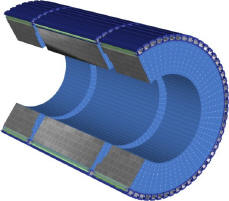
TileCal ATLAS Collaboration (2010) is a sampling calorimeter composed of steel plates (tile shape) as absorber material interleaved with plastic scintillating plates as active material. It is divided in a central barrel (covering ) and two extended barrels (covering ), where each part is formed by 64 modules in order to complete the entire cylinder (see FIG. 1).
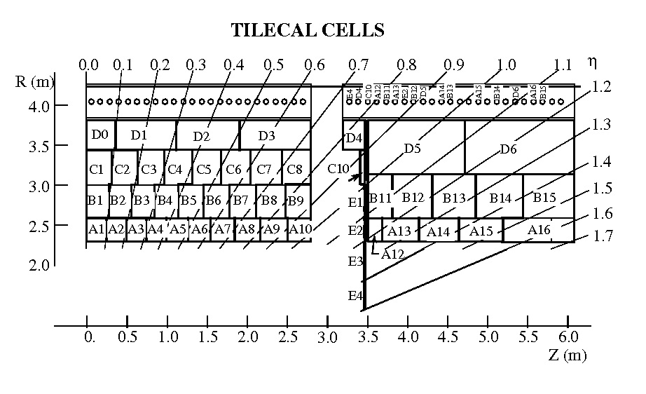
When high energy particles interact with the steel, showers of lower energy particles are created, which in turn produce light when passing through the scintillating tiles. The light is transmitted through wavelength shifting fibers to photomultipliers (PMTs), which convert the light into electrical signals. Adjacent tiles and their WLS fibers are grouped together to form TileCal cells. For each cell the fibers are read-out from two sides by two PMTs. Thus, each cell is read out via two different electrical signal paths. The central barrel modules are divided in up to 45 cells each, while the extended barrels modules are divided in 14 cells. Therefore, TileCal is comprised of approximately 10,000 readout channels. The TileCal cell definition for the half of the central barrel and the extended barrel can be seen in FIG. 2.
The TileCal front-end electronics, located inside the outermost part of the modules, is responsible for processing the PMT signals and transmitting them to the back-end electronics, which is responsible for calorimeter signal acquisition.
The LHC is scheduled to undergo a major upgrade in 2024, preparing for the High Luminosity LHC operation in 2026. Therefore, the ATLAS experiment is currently going through an ambitious 10 years upgrade plan to cope with the LHC luminosity increase. Several detector components should be replaced (e.g. front-end electronics of the calorimeters) and major changes on the trigger system are required to cope with the new luminosity requirements.
The ATLAS upgrade plan for high luminosity is split into three phases: Phase-0 occurred during (Long Shutdown 1), and prepared the LHC for Run 2; Phase-I, foreseen for 2019 (Long Shutdown 2), will prepare the LHC for Run 3, whereafter the peak luminosity reaches cm; finally, Phase-II, which is foreseen for 2024 (Long Shutdown 3), will prepare the collider for the HL-LHC operation ( cm).
The TileCal main activities for Phase-0 were the installation of the new low voltage power supplies, and the activation of the TileCal third layer signal for assisting the muon trigger at (TileMuon Project). During Phase-I, the replacement of the gap scintillators is foreseen. In Phase-II, a major upgrade in the TileCal readout electronics is planned. Except for the photomultipliers tubes (PMTs), most of the on- and off-detector electronics will be replaced, with the aim of digitizing all PMT pulses at the front-end level and sending them with 10 Gb/s optical links to the back-end electronics.
This work describes the major TileCal upgrade activities, focusing on the TileMuon Project and the new on- and off-detector electronics.
II TileCal Electronics and Upgrade Plans for High Luminosity
II.1 TileCal Electronics
The current TileCal signal chain can be seen in FIG. 3. The light produced by energy depositions in the detector is collected by optical fibers and sent to the light mixers, where several fibers are grouped together in order to form the detector cells. The light is converted to an electrical signal in the photomultiplier tube (PMT) and is processed by the 3-in-1 card (Front-End Board), which is responsible for signal conditioning and amplification providing three analog signals as outputs, two for the detector readout (high and low gain) and another for triggering purpose. The low and high gain signals are then digitized at 40 MHz by 10-bit Analog to Digital Converters (ADCs) in the Digitizer Boards. Digital signals of all calorimeter cells in a module are merged and formatted into packages and sent via high speed optical links (Interface Board) that connect the on- and off-detector electronics. The on-detector electronics is located in the outermost part of the TileCal module, in the electronics “drawers”.

In the back-end electronics, the main component is the Read-Out Driver (ROD) which performs preprocessing and gathers data coming from the front-end electronics at a maximum level 1 trigger rate of 100 kHz. The ROD sends these data to the Read-Out Buffers (ROB) in the second level trigger ATLAS Collaboration (2011).
Figure 3 also shows the signal path to the first level trigger. The TileCal first level trigger signal is produced by analog summation of up to six signals on the Trigger Board Cerqueira et al. (2007) and its analog output (Had trigger) is sent to the level 1 receiver by means of long twisted pairs cables (around 70 m). An additional output, which is a buffer to the TileCal third layer signal (D-cells), is also available for processing and is currently being prepared for use to provide coincidence for the level 1 muon trigger, envisaging fake muon rate reduction during LHC run 2 (2015-2018). The first level trigger must reduce the event rate from 40 MHz to a maximum of 100 kHz.

The current architecture of the TileCal electronics drawer can be seen in FIG. 4. It is possible to see the low voltage distribution, the four mother boards sections (MoB), the eight digitizer boards (DiB) along the drawer and the single interface board (IB) with two optical links for redundance, sending data to the back-end electronics at a maximum rate of 100 kHz.
II.2 TileCal Upgrade Activities
In this section, the Tilecal major activities for Phase-0 and Phase-II will be briefly described.
II.2.1 Phase-O Activities
One of the main problems encountered during the TileCal operation was the occurrence of very frequent trips of the low voltage power supply (LVPS) with a very strong correlation to the integrated luminosity. In order to solve this problem, a new design of the LVPS has been developed and 38 units were tested in real conditions during 2012 data taking, showing only 1 trip in 2012. Consequently, all LVPS have been replaced by the new ones in the Long Shutdown 1 (LS1) of the ATLAS upgrade program. Additionally, a significant reduction of the electronic noise is observed and the noise distribution becomes more Gaussian.
Another important activity during LS1 was the major consolidation of the on-detector readout electronics, in particular to reinforce weak electrical connections inside the electronics drawer, the second major source of hardware failures during Run 1.
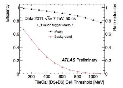
In addition, during LS1 the outermost D layer cells (D5 and D6) of the TileCal extended barrel were integrated in the level 1 muon trigger, together with the end-cap muon trigger chambers, in the context of the TileMuon Project. This will reduce significantly muon fake rates originated from the slow charged particles (protons) in the region while maintaining a good muon efficiency. Figure 5 shows the muon detection efficiency (black dots) and muon fake reduction (red triangles) as a function of the energy threshold applied to the D5+D6 TileCal cells energy, obtained with a prototype receiver module connected to the level 1 calorimeter trigger electronics during Run 1.
An intense activity was required in order to develop the system to process the analog signals from all the outer layer extended barrel cells and provide the coincidence flags for the end-cap muon trigger chambers. The TileMuon Project will be described in more details in Section III.
II.2.2 Phase-II Activities
The main goals of the TileCal Phase-II upgrade are the replacement of the aging electronics, the increase of radiation tolerance, the improvement of system reliability (less connectors - split Main Board design mitigates against single point failure causing loss of cell), to increase data precision and to improve the level one trigger system by the availability of the full detector resolution and improved Signal to Noise Ratio (SNR).
A new on-detector electronics architecture is under design and is being incrementally tested, where three different design options for the new TileCal front-end board are under evaluation. The increased event rate also requires larger currents in the PMT voltage divider chains. New active dividers and a new high voltage power supply are under development. Concerning the off-detector electronics, a new Tile PreProcessor (TilePPr) is being designed to replace the current ROD.
Along with the development of new electronics, a modification of the TileCal mechanics is being considered. The aim is to split the present drawers into two “mini-drawers”. This is compatible with the new electronics architecture. The mini-drawers will simplify handling of the drawers and improve the access to the TileCal electronics since it will be easier to open the detector to replace mini-drawers. Practical solutions to insertion and cooling and electrical connections are being tested with different prototypes.
One upgraded drawer is currently under evaluation tests together with aprototype of the TilePPr. This new “Demonstrator” drawer is backward compatible with the present system so that it can be seamlessly installed in the present system. At the end 2016, one Demonstrator drawer should be installed in the detector in order to be tested under real conditions.
Until 2018, extensive tests should also be performed with the three versions of the new system in test beam after which the decision about the front-end board to choose should be taken. The production of new electronics will take place between 2020-2021. Finally, the installation is foreseen for 2024-2026.
Section IV will describe in more details the new on-detector electronics and the Demonstrator project.
III TileMuon Project
The main goal of the TileMuon Project is the reduction of the muon trigger rate due to slow charged particles (protons), which interact with the muon detector in the end-cap region, by using the TileCal outermost layer signal in the extended barrel region during LHC Run 2 and Run 3. Protons emerging from the end-cap toroid and beam shielding were the main source of trigger background for the muon end-cap trigger chambers. Therefore, TileCal, which is not affected by these protons, can be used in coincidence with the muon end-cap chambers in order to reduce the muon trigger rate.
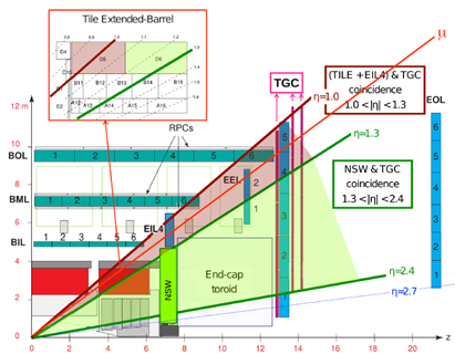
Figure 6 illustrates a transversal cut in the ATLAS detector where is possible to verify that the muons from valid events (comes from the collision point) must cross the TileCal extended barrel before reaching the end-cap muon chambers (TGC) in the region. It is also possible to verify that this region is covered by TileCal D5 and D6 cells.
The TileCal third layer signals were already available for processing as can be seen in the FIG. 3 ( trigger signal at the output of the trigger adder board), although they were not used during LHC Run 1. Therefore, the TileMuon Digitizer Board (TMDB) was designed to process the analog signals from all the outer layer extended barrel cells and provide the coincidence flags for the end-cap muon trigger chambers.
III.1 TileMuon Digitizer Board
The TMDB interfaces 8 TileCal extended barrel modules with 3 sector logic blocks from the end-cap muon chambers. A total of 16 TMDBs, installed in one VME crate, are required to fully equip the detector.
Each board receives 32 channels from the 16 TileCal cells and performs the signal digitization using 8-bit flash ADCs. The digital signals from the 32 channels feed the core FPGA (Spartan 6 from Xilinx), where the energy estimation and signal detection is performed. The optical communication with the muon sector logic is through g-link protocol, implemented on the core FPGA, and using SFP connectors.
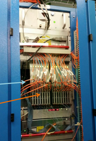
The production of the TMDB boards started by the end of 2014 and the system installation was done in the beginning of 2015. Figure 7 shows the system installed in ATLAS USA15 cavern. The TileMuon system is now in commissioning phase preparing for the beginning of operation late in 2015.
IV New Front-End Electronics for Phase-II
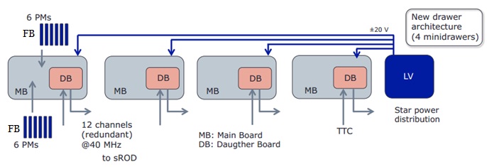
The foreseen architecture for the new on-detector electronics can be seen in FIG. 8. The new readout electronics is composed of: new Front-End boards (FE) that provide conditioning for the PMT signals as well amplification, digitization (depending on the Front-End option) and calibration functionalities; new Main Boards (MB) providing digitization (depending on the Front-End board) and control; and new Daughter Boards (DB) which provide data processing and interface with the back-end electronics via optical links at up to 40 GHz rate with redundance. The star power distribution along with local point-of-load voltage regulators in the new drawer reduces the voltage deviations and the noise coupling along the drawer. Another important change on the drawer architecture is the replacement of a single interface board (actual design) by four Daughter Boards, improving the system robustness and decoupling the drawer electronics into independent units.
IV.1 Front-End - Modified 3-in-1 Card
The Enrico Fermi Institute (University of Chicago) is developing a modified version of the present 3-in-1 card Tang et al. (2013). This Front-End Board is composed of discrete components and can be divided in three stages: the fast signal processing chain, the slow signal processing chain and the calibration electronics and the control bus interface.
The fast signal processing chain includes a 7-pole passive LC shaper, bi-gain clamping amplifiers with a gain ratio of 32 and a pair of differential drivers feeding the analog signals from the low-gain channel and the high-gain channel to the ADCs which are placed in the Main Board. The slow signal processing chain includes a programmable 3-gain integrator which monitors the PMT current induced by a Cesium source and the minimum bias current induced during the collisions. Finally, the last stage includes a precise charge injection circuit, integrator gain control and the control bus interface. This modified version has better linearity and a lower noise level than the previous version. The prototype of the Modified 3-in-1 Card has been built using COTS components and has passed initial radiation tests.
The Modified 3-in-1 Card is currently equipping the Demonstrator drawer and due to that a different version of the board was produced, including an analog output for the Trigger Board in order to preserve the system compatibility with the current level 1 trigger system. Figure 9 shows the Modified 3-in-1 Card.

IV.2 Front-End - QIE Chip
The Argonne National Laboratory together with Fermilab are working on the design of a front-end board which includes a new version of the Charge (Q) Integrator and Encoder (QIE) chip developed in collaboration with Fermilab and CMS HCAL. The QIE includes a current splitter composed of 23 splitter transistors, providing 4 different ranges (16/23, 4/23, 2/23, 1/23), followed by a gated integrator and an on-board 7-bit flash ADC to cover a dynamic range of 18 bits. In this way, only a simple digital interface is needed to communicate with the Main Board. The QIE also includes a charge injection circuit for calibration and an integrator for source calibration. The QIE does not perform pulse shaping, minimizing pile up problems and allowing raw PMT pulses to be measured.
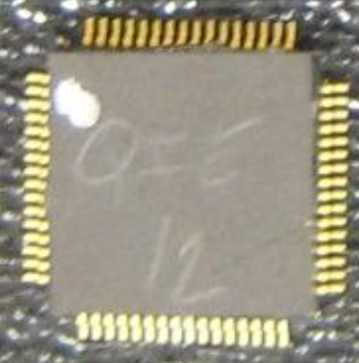
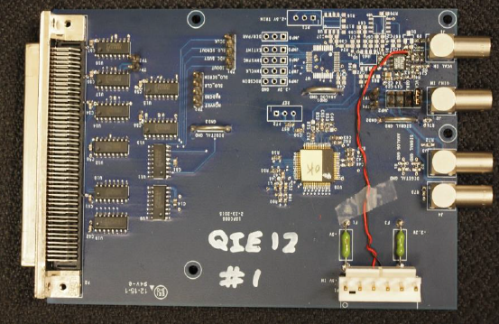
At the present time several successful tests were performed, showing that the performance and radiation tolerance meet the TileCal requirements. The second version of the chip (QIE12) is already in hand and is scheduled for test beam in 2016. Figure 10 shows the QIE12 chip and its prototype test board.
IV.3 Front-End - FATALIC ASIC
FATALIC means Front-End for Atlas TileCal Integrated Circuit Pillet, N. et al (2011), which is being designed at Laboratoire de Physique Corpusculaire in Clermont-Ferrand (LPC). FATALIC includes a multi-gain current conveyor (CC) with three different gains (1, 8, 64) which cover the full dynamic range of the PMT signal, followed by a shaper in order to improve the SNR. The readout chain is completed using an external 12-bit pipelined ADC with a sampling rate of 40 MHz also developed at LPC and called Twelve bits ADC for ATLAS TileCal Integrated Circuit (TACTIC). Moreover FATALIC includes an integrator and a 10-bit ADC with a low sampling rate for calibration purposes. Both chips are designed using the CMOS IBM 130 nm technology.
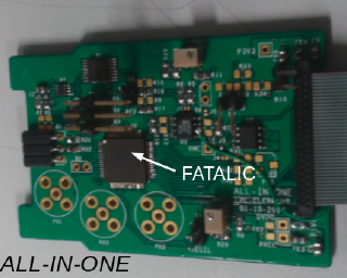
The prototype FATALIC version 4 is currently under tests, showing promising results. The first tests revealed a very good signal to noise ratio and a good linearity over the three gains. The front-end board for the FATALIC is called All-In-One Board and can be seen in FIG. 11.
IV.4 Main Board and Daughter Board
The Main Board Eriksson et al. (2011); Tang et al. (2015) is responsible for the digital control of the FEs, data organization and for the transmission of the data to the Daughter Board. The current prototype design (version 2) digitizes the signals coming from 12 Modified 3-in-1 Cards by using twenty four 12-bit ADCs working at a sampling rate of 40 MHz and is being used in the Demonstrator. Figure 12 shows the Main Board version 2.

The Daughter Board Eriksson et al. (2011); C. Bohn on bahalf of ATLAS Tile Calorimeter System (2012) is intended to serve as a processing board in the next TileCal electronics drawer and is designed for redundancy and high data throughput readout. The two separately programmable FPGAs are responsible for reading out signals originating from the same tile cells but from different sides of the scintillating tiles. This means that they process equivalent data. If one chain fails it can be replaced by the other (there is a loss of statistics though). The Daughter Board sends the digitized data to the super Read Out Driver (sROD) via high-speed links using the GBT protocol Baron et al. (2009). In order to perform these functions, the third version of the Daughter Board includes two Xilinx Kintex 7 FPGAs, one Gb/s QSFP+ and two transmitters using two QSFPs connectors. The board includes fully redundance. The Daughter Board version 3 can be seen in FIG. 13.
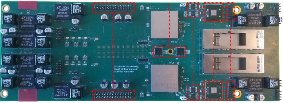
The Daughter and the Main boards have been designed by the Stockholm University and the Enrico Fermi Institute (University of Chicago). The Main Board version 2 and the Daughter Board version 3 have been produced and tested. Both boards are being used on the Demonstrator drawer C. Bohn on bahalf of ATLAS Tile Calorimeter System (2012); Tang et al. (2015).
IV.5 Demonstrator
A Demonstrator project has been established in order to test the feasibility and performance of the proposed upgrade electronics. It should contain as much of the final Phase 2 design as possible while being compatible with the present system.
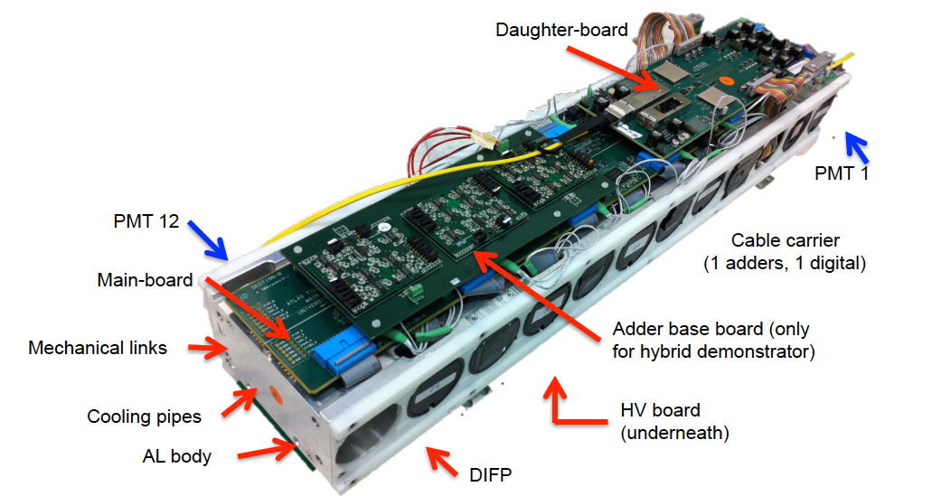
The tests with a hybrid demonstrator drawer, which provides both digital and analog trigger data, are currently being performed. Test beam campaigns are planned for 2015-2016 before the installation in the detector by the end of 2016.
Figure 14 shows one demonstrator drawer that is currently being tested at CERN. The Modified 3-in-1 Cards are placed inside the PMTs in the holes of the aluminum body, the Daughter Board (DB) is on the top right of the figure, the Main Board is below DB and the Adder Base Board. The adders are mounted on the Adder Base Board in order to provide the analog trigger signal to level 1.
V Conclusions
TileCal is facing challenging R&D activities due to the required upgrade for the luminosity increase at LHC.
For the LHC Run 2, the main upgrade activities were related to the replacement of the LVPS and the activation of the D-layer signal in order to be used in coincidence with the muon end-cap trigger.
The replacement of the LVPS improved the detector reliability and, in addition, a significant reduction of the electronic noise was observed.
In order to receive and process the TileCal muon trigger signals in the extended barrel region, the TMDB was designed, fully tested and produced. The TileMuon system is now in commissioning phase preparing for the beginning of operation by the end of 2015.
Concerning the upgrade Phase-II, the on- and off-detector electronics must be redesigned. For the on-detector electronics, three different Front-End boards approaches are being considered. Additionally, in order to provide sufficient data processing, control and interface with the new back-end electronics, a Main Board and Daughter Board combination are being designed.
Extensive laboratory tests are currently being performed with one full Demonstrator drawer, providing promising results.
One Demonstrator drawer should be installed into the detector by the end of 2016. The final decision about the Front-End Board design should be taken by the end of 2018. The production of the new Tilecal readout electronics will take place during 2019-2020 and should be prepared for installation during Phase-II.
Acknowledgements.
I would like to thank my colleagues from the Tile Calorimeter Group for the fruitful discussions and UFJF, CNPq, CAPES and FAPEMIG from Brazil for the support to this work.References
- ATLAS Collaboration (2008) ATLAS Collaboration, “The atlas experiment at the cern large hadron collider,” Journal of Instrumentation 3, S08003 (2008).
- ATLAS Collaboration (2010) ATLAS Collaboration, “Readiness of the atlas tile calorimeter for lhc collisions,” The European Physical Journal C 70, 1193–1236 (2010).
- ATLAS Collaboration (2011) ATLAS Collaboration, “Performance of the ATLAS Trigger System in 2010,” Eur. Phys. J. C 72, 1849. 63 p (2011).
- Cerqueira et al. (2007) A. S. Cerqueira, J. M. Seixas, and L. P. Calôba, “Analog system for building the first-level triggering signal provided by the hadronic calorimeter of atlas detector,” Nucl. Instrum. Meth. A 570, 117–125 (2007).
- Ishino et al. (2013) M. Ishino, T. Sumida, A. S. cerqueira, and T. C. Xavier, “Muon Detection Efficiency and L1_MU20_Endcap rate Reduction with TileCal D5+D6 Cell Energy,” https://twiki.cern.ch/twiki/pub/AtlasPublic/TileCaloPublicResults/EffvsThres_b.pdf (2013).
- Tang et al. (2013) F. Tang, K. Anderson, G. Drake, J. Genat, M. Oreglia, J. Pilcher, and L. Price, “Design of the Front-End Readout Electronics for ATLAS Tile Calorimeter at the sLHC,” Nuclear Science, IEEE Transactions on 60, 1255–1259 (2013).
- Pillet, N. et al (2011) Pillet, N. et al, “FATALIC, a wide dynamic range integrated circuit for the tilecal VFE Atlas upgrade,” in Topical Workshop on Electronics for Particle Physics Conference (TWEPP), http://hal.in2p3.fr/in2p3-00643583 (2011).
- Eriksson et al. (2011) D. Eriksson, K. Anderson, C. Bohm, H Kavianipour, S. Muschter, M. Oreglia, and F. Tang, “A prototype for the upgraded readout electronics for tilecal,” in Topical Workshop on Electronics for Particle Physics Conference (TWEPP), http://iopscience.iop.org/article/10.1088/1748-0221/7/02/C02006/pdf (2011).
- Tang et al. (2015) F. Tang, H. Akerstedt, K. Anderson, C. Bohn, K. Hildebrand, S. Muschter, and M. Oreglia, “Upgrade analog readout and digitizing system for atlas tilecal demonstrator,” Nuclear Science, IEEE Transactions on 62, 1045–1049 (2015).
- C. Bohn on bahalf of ATLAS Tile Calorimeter System (2012) C. Bohn on bahalf of ATLAS Tile Calorimeter System, “A hybrid readout system for the atlas tilecal phase 2 upgrade demonstrator,” in IEEE NSS/MIC Nuclear Science Symposium and Medical Imaging Conference (2012) pp. 1416–1419.
- Baron et al. (2009) S. Baron, J.P. Cachemiche, F. Marin, P. Moreira, and C. Soos, “Implementing the gbt data transmission protocol in fpgas,” in Topical Workshop on Electronics for Particle Physics Conference (TWEPP) (2009) pp. 631–635.