Design, development and performance study of six–gap glass MRPC detectors
Abstract
The Multigap Resistive Plate Chambers (MRPCs) are gas ionization detectors with multiple gas sub–gaps made of resistive electrodes. The high voltage (HV) is applied on the outer surfaces of outermost resistive plates only, while the interior plates are left electrically floating. The presence of multiple narrow sub–gaps with high electric field results in faster signals on the outer electrodes, thus improving the detector’s time resolution. Due to their excellent performance and relatively low cost, the MRPC detector has found potential application in Time–of–Flight (TOF) systems. Here we present the design, fabrication, optimization of the operating parameters such as the HV, the gas mixture composition, and, performance of six–gap glass MRPC detectors of area 27cm 27 cm, which are developed in order to find application as trigger detectors, in TOF measurement etc. The design has been optimized with unique spacers and blockers to ensure a proper gas flow through the narrow sub–gaps, which are 250 m wide. The gas mixture consisting of R134A, Isobutane and SF6, and the fraction of each constituting gases has been optimized after studying the MRPC performance for a set of different concentrations. The counting efficiency of the MRPC is about 95% at kV. At the same operating voltage, the time resolution, after correcting for the walk effect, is found to be about ps.
Keywords:
MRPC, RPC, Gas Ionization Detectors, Time Resolution1 Introduction
The Multigap Resistive Plate Chamber Detector was conceptualized and developed in 1996 CerronZeballos:1995iy ; Williams:2001ms . These detectors are gas ionization detectors with multiple sub–gaps, consisting of resistive plates (glass in our case) separated from one another using spacers of equal thickness. Even though there are many gaps, there is a single set of anode and cathode readout electrodes, placed at the outer surfaces of the two outermost resistive plates. The interior plates are left electrically floating. The narrower sub–gaps enhance their time resolution capability.
The results from groups involved in the study of various MRPC configurations indicate that a time resolution of less than ps can easily be obtained with MRPC detectors. The MRPCs have been chosen as optimal elements for many Time–Of–Flight (TOF) detector systems (including ALICE and STAR) due to their excellent time resolution and higher efficiency for particle detection Fonte:1999cb . The test prototype module with 4 gap MRPC detectors of area 3 m2, developed for the very large area TOF array of the ALICE experiment, had a time resolution of about 70 ps Akindinov:2000rq ; Williams:2001ms . Later on, the MRPCs are upgraded with 5 sub–gaps each in two cells, and the time resolution was 50 ps or better Akindinov:2009zza ; Alici:2013 . MRPC Modules of 6 gas–gaps of 0.220 mm and pad area of 20 cm2, developed for the STAR experiment at RHIC, have a time resolution of the order of ps Bonner:2003 ; Wang:2005 . The MRPC detectors have also been tested in streamer and avalanche modes Narita:2009 . The studies on the gas mixture also show that the baseline mixture of about 90% of C2F4H2, about 5% of C4H10 and the rest of SF6 is suited for the detectors Akindinov:2004 .
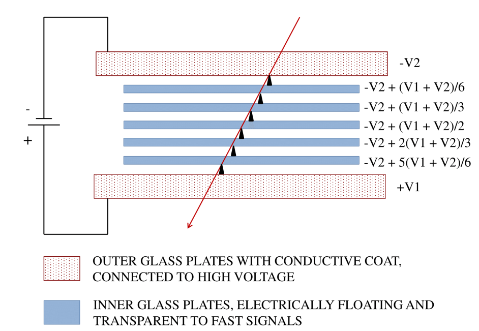
The working principle, including the avalanche formation of an MRPC are similar to that of a single gap RPC, apart from the fact that, the additional sub–gaps improves the space–charge effect and limits the avalanche growth above a certain limit and reduces the time jitter of the signal. An illustration of an MRPC in the ideal case is shown in Figure 1, where all the gas gaps are assumed to be of uniform width. The interior plates are electrically floating, and are maintained at equal voltages due to the flow of positive ions and electrons between them. The voltage across each sub–gap is the same. Hence on the average, each sub–gap will produce the same number of avalanches when a flux of charged particles passes through it. This means the flow of electrons and ions into the plates bounding a gas gap will be identical for all the gaps, and the net current to any of the internal plates would be zero. The surface resistivity of the conductive graphite coat is high enough so that the electrodes act as dielectrics, i.e., they are transparent to the fast signal generated by the avalanches inside each gas gap. The avalanche in any of the sub–gaps will induce a signal to the outermost electrodes, as the inner electrodes are transparent to the fast signals. The fast signals in case of MRPC are produced by the flow of electrons towards the anode. The resultant signal is the summation from all the gas gaps and it enhances the amplitude of the pulse. Copper pickup strips placed outside the cathode and anode electrodes record the signal, with a reduced time jitter, through induction. The intermediate plates act as the physical barriers to an excessive growth of the avalanche, and hence a higher electric field can be applied to the detector operated in the avalanche mode, compared to that of a single gap structure. This is advantageous in terms of the time resolution and rate capability of the device. The strong uniform electric field stimulates the avalanche process immediately after the primary ionization is created by a charged particle, leading to a good time resolution.
MRPCs may consist of a single stack with two external electrodes, or two stacks packed together with three external electrodes, the anode being common for both the stacks Williams:2001ms . Single cell (stack) configuration has a pair of external electrodes. As the number of floating electrodes increases, the operating voltage also increases. A double cell(stack) consists of two single cell MRPCs which are clamped together (usually the anodes). The distribution of the floating electrodes in the two cells reduces the operating voltage to be applied across each individual cell.
The India-based Neutrino Observatory (INO) bib5 is a proposed underground neutrino laboratory with a long–term goal of conducting decisive experiments in neutrino physics and will also house other experiments which require an underground facility in future. Single gap RPC detectors have been chosen as the active detector elements for the magnetized Iron CALorimeter (ICAL) detector, due to their high efficiency, position and timing characteristics besides their long-term suitability for large detector coverage bib6 . However as a part of the extended R&D at INO, MRPC detectors have been developed to find potential application in TOF detectors, medical imaging etc.
Here we present the development and performance of single cell six–gap glass MRPC detectors with each sub–gap being about m thick. In section 2 we present the details of the fabrication procedure and the optimized design. The experimental setup, including the trigger and data acquisition system, are described in section 3. In section 4 we present the MRPC characteristics.
2 Fabrication
In this section we shall discuss about the design and fabrication of the MRPC detectors. We have constructed six-gap glass MRPCs with single cell structure of dimensions mm mm mm. A schematic of the configuration with dimensions of various components is shown in Figure 2. Note that the area of the internal glass plates are of dimension mm mm mm.
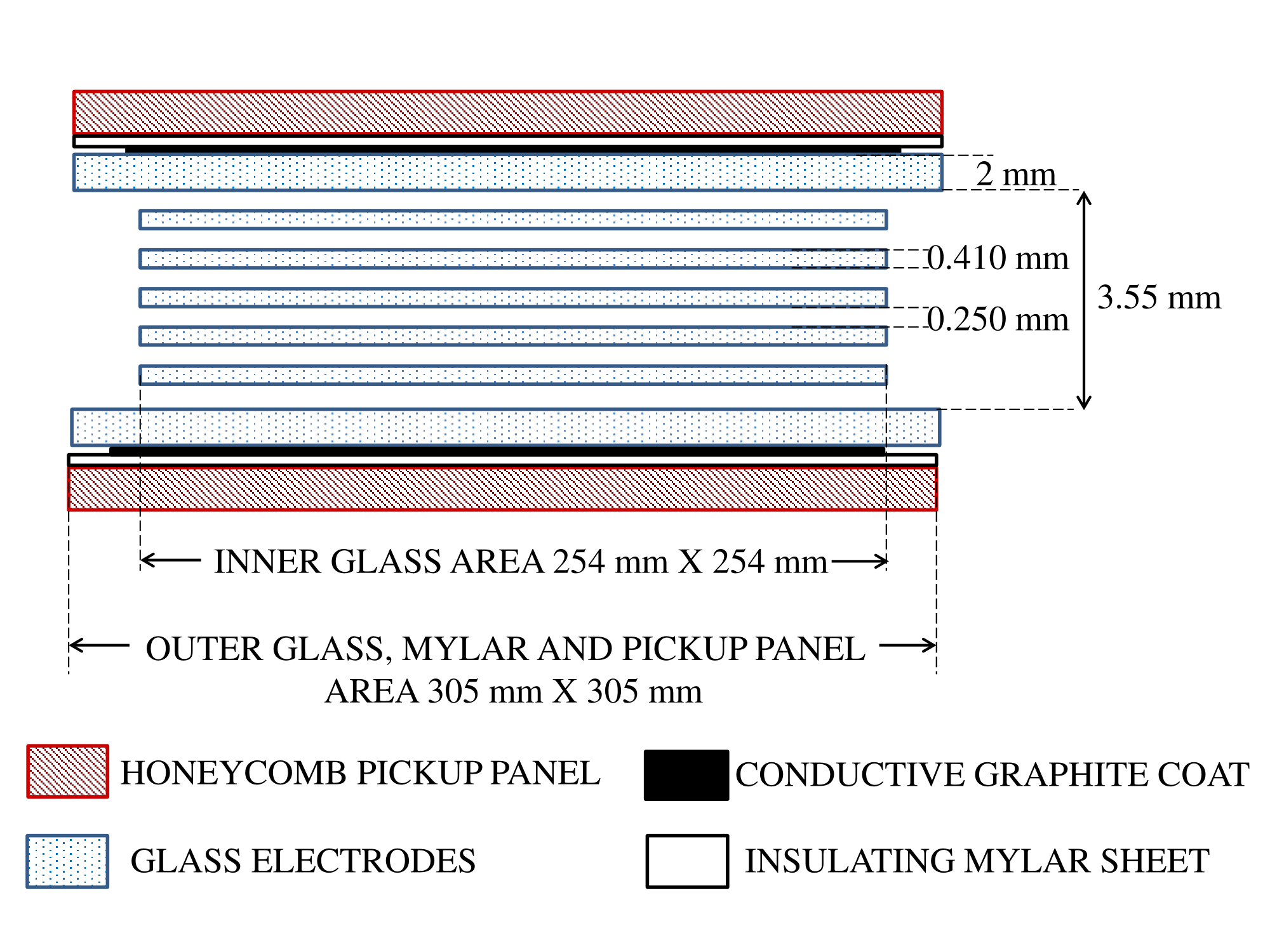
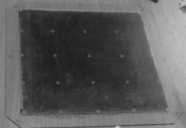
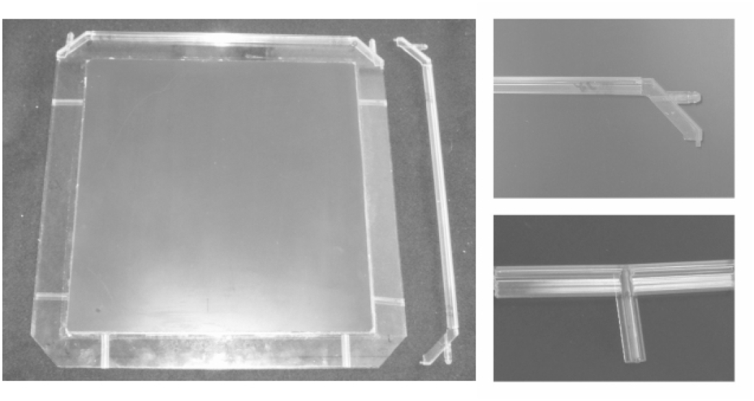
Glass sheets of mm thickness, coated with a conductive layer using graphite and paint of the NEROLAC brand, were used for the outer electrodes. The surface resistance of the conductive coat was in the range ( – ) M/. Two sided non conducting adhesive tapes were used on both sides of a mylar sheet to make small circular spacers of diameter mm and thickness m. Twenty five spacers were used to maintain each gas gap. The placement of the spacers were shown in Figure 3. First a few trials were made by placing this configuration in an enclosed box filled with the gas mixture. Such an enclosed structure had some drawbacks such as difficulty in alignment and the problem of ensuring sufficient and uniform gas flow through the sub–gaps. The configuration was optimized by sealing the gas gaps using side spacers glued between the outermost electrodes. As can be seen in figures 2 and 3, there is a gap of around cm from the edges of the external electrodes to the edges of the internal electrodes. There is a possibility of gas following that path of thickness 3.55 mm, instead of flowing through the 0.250 mm thick sub–gaps which would offer much higher resistance to the gas flow. In order to ensure a proper flow through the sub–gaps, we introduced some blockers at appropriate places (one each near the gas inlets and two each near the gas outlets). This is illustrated in Figure 4. The pickup panel consists of honeycomb panels laminated with copper strips of width cm. The pickup strips on both the sides of an MRPC were placed parallel to each other.
3 The Experimental Set-up
The experimental set–up to test three MRPCs with the optimized design is described here. A cosmic muon telescope consisting of three scintillator paddles has been set–up. The details of the telescope, the preamplifier and the data acquisition system are described in the following subsections.
3.1 The cosmic muon telescope
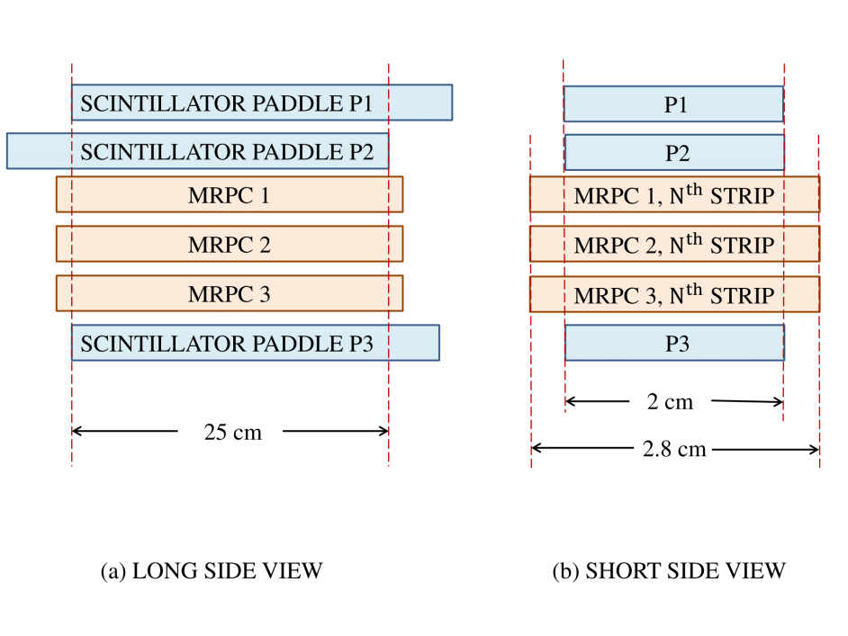
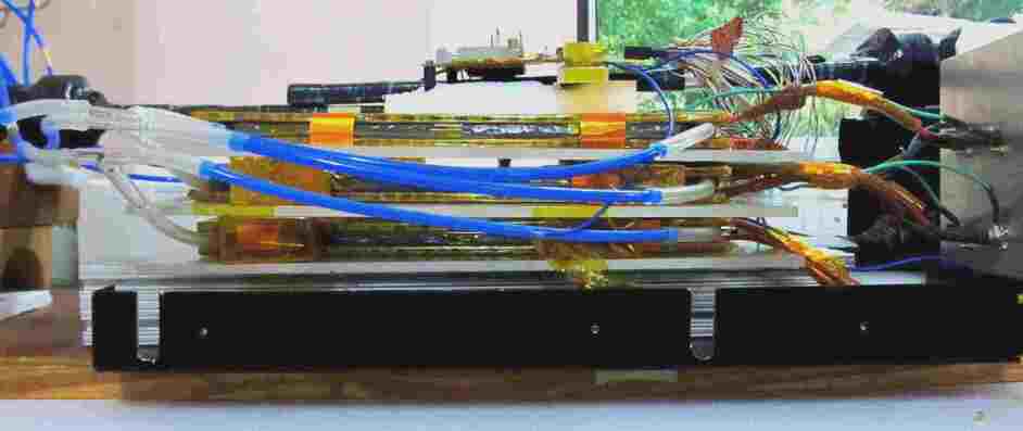
The MRPCs were operated in the avalanche mode and characterized using cosmic muons. Three scintillator paddles of width cm each (two on the top of the MRPCs under test and one at the bottom) were set up to construct a cosmic ray muon telescope as illustrated in Figure 5. A fast time coincidence of signals from these paddles indicates the passage of a cosmic ray muon through the detector set–up. This coincidence signal has been used to trigger the data acquisition system. The set–up including three MRPCs and three scintillator paddles is shown in Figure 6.
| Threshold voltage | Count rate | Threshold voltage | Count rate |
| (mV) | (Hz) | (mV) | (Hz) |
3.2 NINO ASIC
For amplification and digitization, NINO ASIC, an ultra fast front end preamplifier-discriminator chip which was developed for the ALICE TOF experiment, was used bib7 . Each chip has amplifier and discriminator channels. Each channel is designed with an amplifier with < ns peaking time, a discriminator with a minimum detection threshold of fC, and an output stage. Each channel in the NINO ASIC chip takes differential signals from the pickup strips as input, and amplifies them in a four stage cascade amplifier. The threshold to the discriminator stage of the chip was set at mV after studying count rates of the detector at various values as summarized in Table 1.
3.3 DAQ
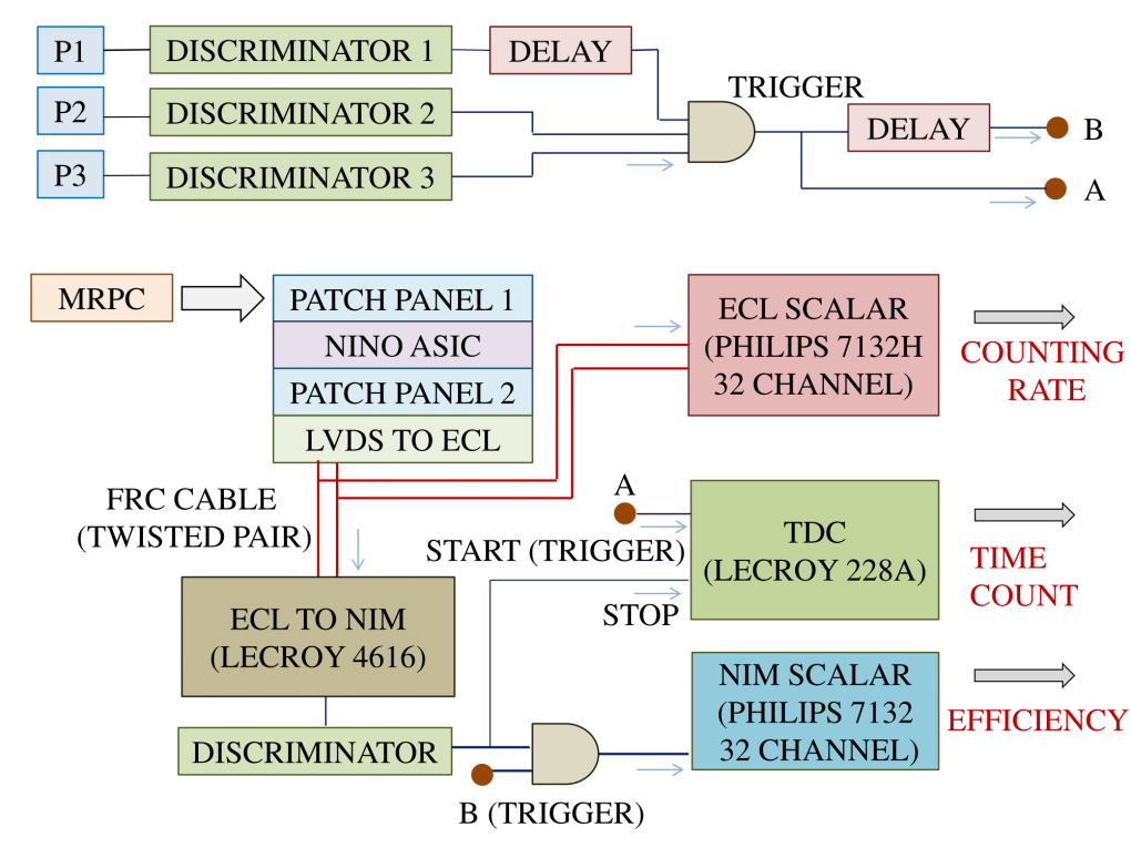
We have assembled a CAMAC based data acquisition (DAQ) system for the MRPC detector test set–up. MRPC pickup strips are amplified and digitized by NINO ASICs and then taken to the time coincidence unit for generating the trigger. The differential (LVDS) signals obtained from NINO outout are converted to ECL and then according to the requirement of the scalar and TDC used directly or further converted to NIM signals. The counting rate of the individual strips are recorded with a ECL scalar. The trigger (T) is formed by generating a coincidence between the three scintillator paddles P1, P2 and P3. The efficiency of the MRPC strips is then obtained from the coincidence of the trigger and the strip count. Note that, for parts of the time resolution study the NINO ASIC has been replaced by ANUSPARSH anusparsh , a front–end ASIC designed for the INO-ICAL experiment, which also provides the analog output signal.
| (1) |
The trigger is also given as the start to the TDC module to get the time count, where the Stop signal comes from the MRPC strips. The DAQ scheme to obtain the counting rate, efficiency and timing is shown in Figure 7.
4 The MRPC performance
Here we discuss the characteristics of MRPC obtained by adjusting various parameters such as gas mixture composition, HV etc. The I-V characteristics, strip count rate, efficiency and the time resolution has been studied.
4.1 MRPC Characteristics as a function of Gas mixture and HV
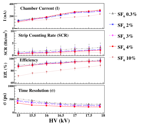
The gas mixture is composed of R134A, C4H10 and SF6 gases. Various studies show that the MRPCs are best operated with of SF6 unlike the standard composition used to operate single gap RPC. With increasing SF6 fraction, two competing processes affect the MRPC characteristicsAkindinov:gasmixture . Higher electric fields are required with increasing fractions of SF6, which also increases the drift velocity and results in an improved time resolution. On the contrary, since SF6 has large capture cross sections for low energy electrons, increasing the SF6 concentration reduces the growth in the avalanche significantly. This leads to a reduction in the MRPC counting rate and efficiency, and a worsening in the time resolution. So, an optimization of the gas mixture composition is required for balancing these two opposing effects.
We have performed a study with various concentrations of SF6 at different applied high voltages to obtain an optimized set. For this, the proportion of C4H10 was kept fixed at , and the other two were varied. Figure 8 shows the efficiency, counting rate per area of the pick-up strip, the chamber current and the time resolution of an MRPC strip as a function of the applied HV which was varied between kV and kV. We see that at of SF6, the time resolution is the best and the noise rate and chamber current are reasonable without deteriorating the efficiency. So for further study, we have used the gas mixture of R134A (), C4H and SF. We see that even at kV the chamber current and counting rate are not too high. In Figure 8, the time resolution of the MRPC, after correcting for the time walk has been shown. This correction is done via a calibration of the prompt time peak with the total charge deposited in an event. This is described in the following section.
4.2 Time resolution
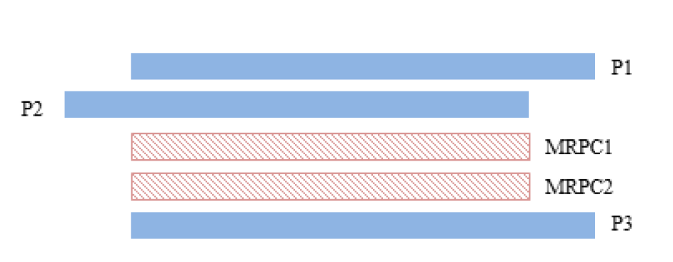
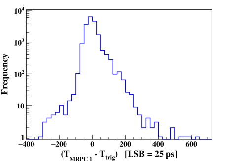
The introduction of smaller gas sub–gaps results in an improved time resolution in MRPCs. For an accurate measurement of the timing, it is important to reduce any fluctuations which may occur during the generation of the timing logic signal. A major source of finite time resolution is the walk effect. This effect is caused by the variation in the signal amplitudes and/or rise time. The signals with different amplitudes cross the discriminator threshold at different times, resulting in a time shift (walk) in the logic signal. An additional walk effect arises due to the finite amount of charge that is required to be integrated on a capacitor to trigger the discriminator. We reduce the time walk by calibrating the time counts with the charge deposited. A setup of two MRPCs and three scintillator paddles, as shown in Figure 9, has been used for this study. The trigger has been provided by the coincidence of the three scintillator paddles and this has been used as the ‘Start’ to the TDC. A delay is added to the scintillator P1, so that the timing of the trigger is governed by it. In Figure 10, a distribution of the MRPC timing, with respect to the scintillator trigger has been shown. A correction for time walk has been made according to the charge of the signal, which is described in the following. Note that, the charge is obtained from the analog output signal from the MRPC strips. Since the NINO ASIC provides LVDS output only, for this study it has been replaced with ANUSPARSH, a front-end ASIC designed for the INO-ICAL experiment.
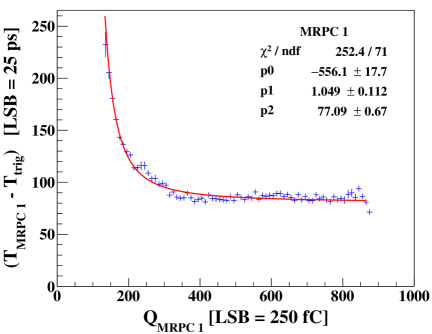
The two dimensional profile histogram of time counts vs charge counts is shown in Figure 11. This is fitted to a function . The time count of each event is then corrected according to the charge information by employing a calibration through the fit parameters as follows,
| (2) |
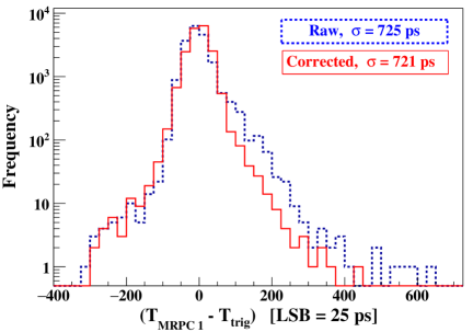
where, is the correction to be obtained from the time counts as a function of the charge as obtained from the calibration fit. The comparison of the raw and corrected time distributions is shown in Fig. 12, which show clear reduction in the tail.
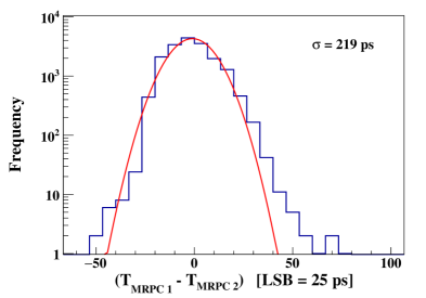
The time distribution of MRPC1 with respect to MRPC2 is shown in Figure 13, for kV. The time resolution is ps, which also includes – ps of jitter from the electronics. This jitter has been estimated by replacing the MRPC strip signals with a pulser and observing the obtained time spectrum.
4.3 MRPC as a part of trigger to single-gap RPC

We then probe the MRPC potential by adding it to the external trigger system for a single-gap RPC. In Figure 14 we show the three different set–ups which were used. In the first set–up, the trigger is formed by generating a coincidence between two scintillator paddles P1 and P2. For the other two set–ups, the MRPC is added to the trigger. The various characteristics of the single-gap RPC from these three trigger set–ups are listed in Table 2. We see that the introduction of the MRPC in the trigger system helps in improving the time resolution.
| Set–up | Trigger | Eff. | Time res. | Noise | I |
| () | (ns) | () | (nA) | ||
| I | P1, P2 | 85 | 1.42 | 1.5 | 305 |
| II | P1, P2, MRPC | 85.9 | 0.87 | 2.85 | 312 |
| III | P1, P2, MRPC | 87.8 | 0.85 | 1.87 | 311 |
5 Summary
In this paper we have presented the development procedure of six–gap MRPC detectors and their performance. The MRPC design has been optimized to ensure a uniform and proper gas flow through the sub–gaps. The gas mixture used is R134a (), , . The characteristics like efficiency, time resolutions etc. were studied at different operating voltages. We see a marked improvement in the time resolution after applying an off–line correction for time-walk. At an operating voltage of kV, the time resolution is obtained to be ps, including the electronic jitter. An MRPC, used as a part of the external trigger to a single gap RPC, also reduces the time jitter of the trigger significantly. A stack of three MRPC detectors is now fully operational.
This setup will now be used for a TOF measurement study. It is also being planned to fabricate MRPCs with double cell configuration, which would enable us to explore the characteristics at applied voltages higher than kV.
6 Acknowledgement
This work is a part of the extended detector studies by the INO Collaboration. We would like to thank P. Verma, S. R. Joshi, S. Kalmani, Mandar Saraf, Darshana Gonji, Santosh Chavan and Vishal Asgolkar for their help during the course of this work. We also express our gratitude to Prof. V.M. Datar and Prof. G. Majumder for the critical reading of the manuscript and many useful suggestions. MMD acknowledges the support from the Department of Atomic Energy (DAE) and the Department of Science and Technology (DST), Government of India. MMD also thanks the Weizmann Institute of Science for their hospitality, where parts of the manuscript were written.
References
- (1) E. Cerron Zeballos, I. Crotty, D. Hatzifotiadou, J. Lamas Valverde, S. Neupane, M. C. S. Williams and A. Zichichi, Nucl. Instrum. Meth. A 374, 132 (1996).
- (2) M. C. S. Williams [ALICE Collaboration], Nucl. Instrum. Meth. A 478, 183 (2002).
- (3) P. Fonte et al. [ALICE Collaboration], Nucl. Instrum. Meth. A 443, 201 (2000).
- (4) A. Akindinov, F. Anselmo, M. Basile, E. Cerron Zeballos, L. Cifarelli, F. Cindolo, J. Choi and B. Cozzoni et al., Nucl. Instrum. Meth. A 456, 16 (2000).
- (5) A. Akindinov et al., Nucl. Instrum. Meth. A 602, 709 (2009).
- (6) A. Alici et al. [ALICE Collaboration], Nucl. Instrum. Meth. A 706, (2013) 29-32.
- (7) B. Bonner et al., Nucl. Instrum. Meth. A 508, (2003) 181-184.
- (8) Y. Wang et al., Nucl. Instrum. Meth. A 538 (2005) 425-430.
- (9) S. Narita et al, Nucl. Instrum. Meth. A 602 (2009) 814-816.
- (10) A. Akindinov, A. Alici, F. Anselmo, P. Antonioli et al., Nucl. Instrum. Meth. A 533 (2004) 74-78.
- (11) M. S. Athar et al. [INO Collaboration] India-based Neutrino Observatory: Project Report. Volume I., INO-2006-01.
- (12) V. M. Datar et al., Nucl. Instrum. Meth. A 602 (2009).
- (13) F. Anghinolfi et al., Nucl. Instrum. Meth. A 533 (2004) 183-187.
- (14) V.B. Chandratre et al., Proceedings of the DAE–BRNS Symp. on Numcl. Phys 60 (2015) 928–929.
- (15) A. Akindinov, A. Alici, F. Anselmo, P. Antonioli et al., Nucl. Instrum. Meth. A 533 (2004) 93-97.