Three-Dimensional Simulation of Biological Ion Channels Under Mechanical, Thermal and Fluid Forces
Abstract.
In this article we address the three-dimensional modeling and simulation of biological ion channels using a continuum-based approach. Our multi-physics formulation self-consistently combines, to the best of our knowledge for the first time, ion electrodiffusion, channel fluid motion, thermal self-heating and mechanical deformation. The resulting system of nonlinearly coupled partial differential equations in conservation form is discretized using the Galerkin Finite Element Method. The validation of the proposed computational model is carried out with the simulation of a cylindrical voltage operated ion nanochannel with K+ and Na+ ions. We first investigate the coupling between electrochemical and fluid-dynamical effects. Then, we enrich the modeling picture by investigating the influence of a thermal gradient. Finally, we add a mechanical stress responsible for channel deformation and investigate its effect on the functional response of the channel. Results show that fluid and thermal fields have no influence in absence of mechanical deformation whereas ion distributions and channel functional response are significantly modified if mechanical stress is included in the model. These predictions agree with biophysical conjectures on the importance of protein conformation in the modulation of channel electrochemical properties.
1. Introduction and Motivation
Ion channels connect the intracellular environment and the surrounding biological medium, allowing the dynamical exchange of the chemical species that supervise the functions of every cell in the human body. Ion channels control electrical signal transmission among excitable cells, notably, muscle cells and/or neurons, and because of their fundamental role they have been subject to biophysical and mathematical investigation for a long time.
The most commonly used approach to ion channel modeling is based on the representation of the cell membrane lipid bilayer as an equivalent electrical circuit including capacitive and conductive elements, these latter being in general described by a nonlinear current-voltage characteristic. The resulting formulation is constituted by a nonlinear system of ordinary differential equations (ODEs) whose best known example is the Hodgkin-Huxley (HH) model [23, 25]. We refer to [35, 17] for a detailed treatment of ODE-based differential models and their application to relevant problems in Computational Biology.
ODE differential models are widely used because of their limited computational cost and ease of implementation. However, their biophysical accuracy is limited and often allows to characterize only basic properties of the cellular system under investigation, such as the homeostatic Nernst potential [22], and/or to reproduce simple experiments in Electrophysiology, such as the transmembrane current in voltage clamp conditions [26, 24].
To analyze the fundamental mechanisms that govern ion transport across a membrane channel, a higher model complexity is required. With this aim, a system of partial differential equations (PDEs) expressing the balance of mass and of linear momentum for each ion species can be adopted to describe the dynamical balance of electro-diffusion forces acting on chemicals flowing across the cell membrane bilayer. The resulting formulation is represented by the Poisson-Nernst-Planck (PNP) model for ion electro-diffusion. We refer to [4, 6, 46, 5], for a detailed illustration of the PNP differential system and a discussion of its mathematical and numerical properties.
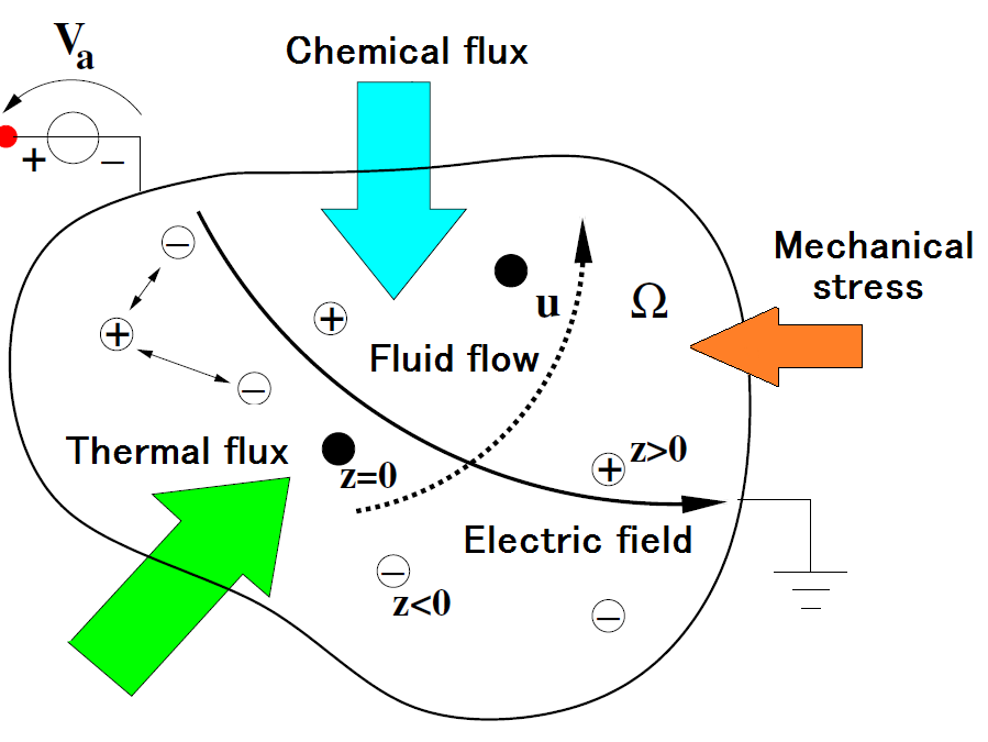
In the present work we address the three-dimensional (3D) study of a generalized version of the PNP model, modified by including the effect of electrolyte fluid convective transport, a thermal gradient and mechanical forces. The extension of the PNP system accounting for fluid velocity is well-known as the velocity-extended PNP model and has been the object of extensive mathematical and numerical investigation in [49, 32, 33, 52, 42]. In these pages we adopt a wider vision of ion transport as schematically depicted in Fig. 1 where is an open bounded domain representing the bio-physical system that includes the ions in motion through a physiological fluid under the action of several externally applied forces: electrical, thermal, chemical and mechanical. Each of these external forces contributes to determining ion flow in the medium according to the effect of the following vector fields:
-
(1)
electric field;
-
(2)
concentration gradient;
-
(3)
thermal gradient;
-
(4)
electrolyte fluid.
In typical applications of Electrophysiology and Cellular Biology the electric field may be the result of the application to the cell of an external voltage drop such as in a patch clamp experiment [43, 37, 30], and/or the presence of fixed charged ions embedded in the portion of lipid bilayer surrounding a transmembrane channel [22, 56]. The ion concentration gradient may be the result of the administration of a substance such as a drug or a toxin [18, 54, 29, 59], whereas the thermal gradient may be the result of the activation of heat-sensitive thermo-transient receptor potential (thermo-TRP) cation channels exposed to capsaicin, a natural ingredient of spicy foods such as red hot chilli peppers and of cold-sensitive TRP channels exposed to menthol [13, 57]. Ion motion can also be activated by a physiological fluid shear stress acting on a mechanosensitive ion channel [50]. Conversely, ion motion can determine a modification of the physical properties of the surrounding environmnent through the effect of electro-osmotic pressure [34, 15], whereas the mechanical action can be determined by the chemicals signal acting to change the size of the channel or of the vessel in which the fluid flows as in the mechanism of neurovascular coupling [2, 44].
The 3D simulation of the Generalized PNP equations (for short, GenPNP) including electrolyte fluid convective transport, thermal gradient and mechanical forces is a formidable task. The presently available computer resources and numerical discretization schemes, the Galerkin Finite Element Method (GFEM) in our case, open the possibility to explore at the cellular scale, to the best of our knowledge for the first time, the multi-physics complexity of the phenomena illustrated above. The computational structure devised to numerically solve in a fully self-consistent manner the GenPNP system is part of the software MP-FEMOS (Multi-Physics Finite Element Modeling Oriented Simulator) that has been developed by some of the authors [42, 41, 1]. MP-FEMOS is a general-purpose modular numerical code based on the use of the GFEM implemented in a fully 3D framework through shared libraries using an objected-oriented programming language (C++). Several kinds of finite elements on simplexes are included for appropriate discretization of the various PDEs constituting the problem at hand. In particular, the electro-chemical and thermal blocks are solved using the exponentially fitted edge averaged (EAFE) piecewise linear finite element scheme studied in [19] and [58]; the flow of the incompressible electrolyte fluid is solved using the Taylor-Hood finite element pair (see [48], Chapter 9), whereas the mechanical deformation of the channel is numerically computed using standard piecewise linear finite elements.
An outline of the article is as follows. In sec. 2 we introduce the basic notation of the problem at hand, its geometry and partition into simplices. In sec. 3 the mathematical model of the GenPNP system is discussed in detail. In sec. 4 the solution algorithm employed to decouple the various blocks of the full system is described. Sec. 5 is devoted to illustrate the weak formulation for each differential subproblem whereas sec. 6 treats the adopted finite element discretization schemes. Sec. 7 contains an extensive bouquet of simulations aimed at validating the biophysical accuracy of model and computational schemes. Finally, sec. 8 collects concluding remarks and future research objectives.
2. Basic Notation, Geometry and Geometrical Discretization
Referring to Fig. 1, in this section we introduce the basic nomenclature associated with the multi-physics problem, the computational domain in which the problem has to be solved and its geometrical discretization needed for the subsequent numerical approximation with the GFEM.
2.1. Geometry and notation
Let and denote the spatial and temporal coordinates, respectively. The simulation domain is assumed to be an incompressible, viscous and Newtonian fluid moving with velocity , in which chemical species are dissolved. Each chemical has effective charge , , and concentration (number density) []. Cations have , anions have while neutral species have .
We denote by the boundary of the domain and by the unit outward normal vector on . Let denote the set of dependent variables of the problem, , and representing the electric potential, temperature and mechanical displacement field solutions of the biophysical system under investigation. Then, with each variable , we associate a partition of the domain boundary into the union of (generally different) subsets. We indicate by the subset of where a Dirichlet condition and by the subset where a Neumann condition is applied, in such a way that and .
2.2. Geometrical discretization of the computational domain
In view of the numerical approximation of a given differential problem, the MP-FEMOS computational platform provides a flexible Galerkin Finite Element discretization on a fully unstructured triangulation of the domain into tetrahedral elements , such that .
For all , we let be the diameter of , defined as the longest edge of , and indicate by the discretization parameter. We assume to be a regular partition (cf. [48], Chapter 3), i.e., that there exists a positive constant (independent of ) such that
| (1) |
being the diameter of the largest sphere inscribed in . Condition (1) is equivalent to assuming a bound from below of the minimum mesh angle.
3. Mathematical Model
In this section we illustrate the multi-physics model for ion electrodiffusion in the biological environment schematically represented in Fig. 1.
Ion and fluid motion are mathematically described by a coupled systems of PDEs including: the velocity-extended Poisson-Nernst-Planck (VE-PNP) equation system to account for electro-chemical forces and the Stokes equation to account for fluid forces under the assumption that nonlinear convective effects can be neglected because of slow fluid motion.
Thermal dispersion into the channel is considered by a heat conduction equation that allows to determine temperature evolution at all .
To calculate the deformation of the channel wall, the domain is regarded as a compressible linear elastic medium undergoing the classical Navier-Lamé theory. At present, no direct coupling is activated between stress and deformation fields and the PNP system. This modeling limitation will be removed in a future step of our research.
3.1. The VE-PNP Poisson-Nernst-Planck system
A detailed derivation of the PNP systems can be found, e.g., in [42].
By the application of: 1) mass balance for each chemical;
2) linear momentum balance (second law of dynamics);
3) Stokes’ law for viscous drag exerted by a fluid on a
particle in motion through it; 4) Einstein’s relation;
and 5) the law of perfect gases, the following system of
PDEs is obtained:
, solve:
| (2a) | ||||
| (2b) | ||||
| (2c) | ||||
| (2d) | ||||
In (2), the symbol denotes the ion particle flux [], and are the ion electrical mobility and diffusivity and is system temperature. In the Poisson equation (2c), and are the electric field [] and electric potential [], respectively, while and denote the electron charge and the electrolyte fluid dielectric permittivity, respectively. The quantity [] mathematically accounts for the presence of a fixed charge density due to the lipid membrane bilayer and is assumed to be a given function of position only. The diffusion coefficient and the mobility are proportional through the generalized (because is not constant) Einstein’s relation
| (3) |
where is Boltzmann’s constant. Initial conditions for ion concentrations are :
| (4a) | ||||
where the functions are positive given data. The boundary conditions for the VE-PNP system are :
| (5a) | ||||
| (5b) | ||||
| (5c) | ||||
| (5d) | ||||
where is the electrostatic potential of the side and is a given concentration of the chemical species on side . Conditions (5a) and (5c) enforce respectively a given voltage and a given concentration on the side, while (5b) and (5d) enforce a homogeneous Neumann condition, that corresponds for chemical particles to the conservation of mass concentration inside the simulation domain (i.e. particles cannot leave the domain).
The VE-PNP equation system can be regarded as a generalization of the classic Drift-Diffusion (DD) model for semiconductor devices [53, 39, 40, 31] through the addition of the thermomigration and fluid velocity terms in the linear momentum balance equation (2b). As a matter of fact, the third term in (2b) is related to the thermal grandient effect on ion flow while the last term gives rise to an additional translational contribution due to fluid motion and is highlighted by a box. This term represents the coupling between electrolyte fluid motion and electrodiffusive ion transport. Henceforth, we use the reference ”PNP system” every time the contribution of the velocity and of the thermal gradient is neglected in the equation set (2).
3.2. The Stokes system
The Stokes system to describe the slow motion of an incompressible and viscous fluid with a constant density [] consists of the following PDEs (see [48] for a complete mathematical and numerical treatment):
| (6a) | ||||
| (6b) | ||||
| (6c) | ||||
| (6d) | ||||
where is the fluid velocity [], is the fluid pressure [], the fluid shear viscosity [], the stress tensor [] and the strain rate tensor []. The symbol is the second-order identity tensor of dimension 3 whereas the second-order tensor is the symmetric gradient of . Notice that in accordance with the assumption of slow fluid motion, the quadratic convective term in the inertial forces has been neglected in the momentum balance equation (6b). The boxed term at the right-hand side of equation (6b) physically corresponds to the electric pressure exerted by the ionic charge on the electrolyte fluid, and mathematically represents the coupling between electrodiffusive ion transport and electrolyte fluid motion. The initial condition for electrolyte fluid velocity is
| (7a) | ||||
where the function is a given datum, usually set equal to zero. The boundary conditions for the Stokes system are:
| (8a) | ||||
| (8b) | ||||
where is the imposed velocity on the side and is the value of the normal stress on . Relation (8a) is the wall adherence condition (typically ) and (8b) is the application of the action-reaction principle for the normal stress . The presence of the two boxed terms in the linearized momentum balance equations (2b) and (6b) terms requires the adoption of a suitable iterative procedure to successively solve the whole coupled system (2)- (6) as described in sec. 4.
3.3. Heat equation
Ion and fluid motion, as well as the action of mechanical forces, may dissipate energy throughout the channel. The evolution of the resulting channel thermal profile in is obtained by solving the thermal conduction equation (see [36]) given by
| (9a) | ||||
| (9b) | ||||
where is the specific heat [], is the heat flux [], is the thermal conductivity [] and is the heat generation term []. We notice that convective thermal effects due to fluid velocity are neglected in the mathematical definition of the heat flux . Also, we notice that the heat production term is the result of heat source/sink processes such as Joule heating or (possibly nonlinear) thermo-chemical reactions due to the administration of drugs as in TRP channels. For the purpose of the present work, is set equal to zero, but this limitation will be removed in a subsequent step of the research. The initial condition for electrolyte fluid temperature is
| (10a) | ||||
where the function is a positive given datum. The boundary conditions for the channel heat equation are:
| (11a) | ||||
| (11b) | ||||
where is the imposed temperature on the side . Relation (11a) represents the effect of an infinite heat source at temperature while (11b) is the adiabatic condition.
3.4. The Navier-Lamé approach to mechanical equilibrium
The mechanical problem of channel deformation is here described by the model of linear isotropic elasticity including thermal expansion and represented by the following system expressing the equilibrium condition and the generalized Hooke’s law:
| (12a) | ||||
| (12b) | ||||
| (12c) | ||||
where is the displacement [], is the stress tensor [], is the volumetric force density [], is the total strain tensor, is the elastic strain tensor, is the thermal strain tensor, is the elastic tensor [] and is the initial stress []. In particular, if the thermal properties are homogeneous and orthotropic the thermal deformation (strain) is given by the relation
where , and [] are the linear thermal expansion coefficients, and is the reference temperature []. Under standard assumptions (symmetric stress and strain, symmetric and positive definite energy functional and coordinate invariance of mechanical response) the relation between stress and elastic strain becomes
| (13) |
where
are the Lamé coefficients, while is the Poisson ratio and is the Young module [] describing the material mechanical properties. In the mechanical system, at each time level , the boundary conditions are expressed by a given displacement on side or by a stress free surface on side :
| (14a) | ||||
| (14b) | ||||
where is a given boundary displacement.
3.5. Fully coupled multi-physical approach
The multi-physics description of biological ion nanochannels is hence obtained by combining together all the previous blocks as follows:
-
•
Mechanical description (12a)
-
•
Ionic transport (2)
-
•
Thermal description (9a)
-
•
Fluid velocity calculation (6)
We define this as the the Fully Coupled Thermal Velocity Extended Poisson Nernst Planck Stokes system in presence of mechanical forces or, shortly, FC-MF-T-VE-PNP-S model. To the best of our knowledge, such a formulation represents the first example of a multi-physics based formulation for ion channel modeling and simulation.
4. Solution Algorithm
In view of the numerical solution of the FC-MF-T-VE-PNP-S system, for a given time (final simulation time), we introduce the time interval and we divide into a uniform partition of time slabs of width , such that . Then, for each , we denote by:
| (15a) | ||||
| (15b) | ||||
| (15c) | ||||
| (15d) | ||||
the solution vectors at time level of the Mechanical block and those of the Thermal PNP block, of the Stokes block and of the whole coupled problem. The solution of the FC-MF-T-VE-PNP-S system using a monolithic scheme is a formidable computational task. Thus, the use of a decoupled approach is highly desirable. For each discrete time level , , a two-subblock iteration is carried out. In the first step of the iteration the mechanical problem is solved for the displacement . In the second step of the iteration is used to compute the corresponding deformation providing a new domain configuration in which the remaining thermal, electrochemical and fluid blocks of the problem are successively solved. In doing this, temporal semidiscretization is performed using different temporal schemes: a) one-step methods: Backward Euler (BE) and Trapezoidal Rule (TR); b) two-step method: TR-BDF2. We refer to [47], Chapter 11, for a detailed discussion and analysis of these methods.
The flow-chart of the iteration map that is implemented to solve successively each block of the FC-MF-T-VE-PNP-S system is illustrated in Fig. 2 where is the temporal loop counter and is the iteration counter in the PNP cycle. In detail, the successive solution of the T-VE-PNP-S system proceeds as follows.
- Step 1::
- Step 2::
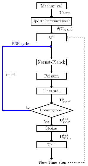
The criterion adopted to monitor the convergence of the solution map of Fig. 2 is to stop the algorithm at the first value of the iteration counter such that
| (16) |
where is a prescribed tolerance, and
| (17) |
is the norm of a vector . In the numerical experiments we set . The above described solution map is a generalization of the classic Gummel decoupled algorithm widely used in contemporary semiconductor device simulation tools for the DD model, and analyzed in detail in the stationary case in [39, 31] and in [40] in the time-dependent case. The convergence rate of the generalized Gummel algorithm is linear; however, there are two main advantages by using such an approach instead of applying, for instance, a fully coupled Newton Method. A first advantage is that in the case of the Gummel method memory cost is strongly reduced so that also the overall computational effort is much less intense. A second advantage is that the Gummel method is more insensitive to the choice of the initial guess than Newton’s iteration. This fact is particularly relevant in multi-dimensional (and, especially, multi-physics) problems, like that under consideration, where the construction of an appropriate initial guess is in general not an easy task, sometimes even impossible.
5. Weak formulation and well-posedeness analysis
In this section we discuss the weak formulation and the well-posedeness of each differential subblock in the solution algorithm of sec. 4. In sec. 5.1 we study the T-VE-PNP system, the Stokes system in sec. 5.2, and the Navier Lamé formulation for the mechanical displacement in sec. 5.3. The analysis of the Poisson equation (2c) and heat equation (9a) is standard and can be found, e.g., in [27, 48]. For ease of notation, we set , , for any function . To avoid technicalities in the subsequent analysis we assume, without loss of generality, that the Dirichlet data (T-VE-PNP system), (Stokes system) and (mechanical system) are equal to zero. Moreover, we restrict the study to the case where the BE method is used for time discretization as the analysis proceeds in a similar manner if the TR or the TR-BDF2 scheme is employed.
5.1. T-VE-PNP system
After time discretization, by using the Einstein relation (3) in (2b) and the boundary conditions (2a) and (2b), the T-VE-PNP system takes the following form: and for all until convergence of the PNP cycle of Fig. 2, solve:
| (18a) | ||||
| (18b) | ||||
| (18c) | ||||
| (18d) | ||||
where is a given function computed by solving the Poisson equation (2c), is the solution of the heat equation (9) and is the diffusion coefficient of species computed using (3) with .
The equation pair (18a)-(18b) is of the admissible form (8.1) of [20]. However, it is immediate to check that the second a priori estimate in formula (8.6) of [20] is, in general, not satisfied preventing a theoretical study of the well posedness of the equation system (18). To overcome this impasse, and also in view of the finite element discretization of (18), we replace the expression (18b) with a suitable approximation. To this purpose, for any function such that for all , we denote the restriction of to an element by and define the piecewise gradient operator as the vector-valued function such that
Finally, we associate with the function its harmonic average defined as
Then, the approximate form of the flux (18b) that is used in this article is
| (19) |
The above definition corresponds to having replaced in the electrical drift term of the flux the local environmental temperature with its harmonic average. It is well known (see [3]) that the use of the harmonic average for rapidly varying functions provides much more accurate results than the usual integral average. It is expected that as the mesh size also the modeling error introduced by using (19) instead of (18b) decreases accordingly.
We now show that the equation system (18) in which the flux (18b) is replaced by (19) is uniquely solvable. Let us introduce the following Hilbert space (see [48] Chapter 1)
| (20) |
Multiplying (18a) by a test function , integrating over and enforcing the boundary conditions (18d) and (18c), we obtain the weak formulation of the T-VE-PNP system: and for all until convergence of the PNP cycle of Fig. 2: find such that
| (21) |
where:
We notice that letting allows us to recover the steady-state problem. Using a standard technique in the analytical and computational study of the DD model for semiconductors, we introduce the change of dependent variable
| (22) |
where is a dimensionless potential such that for each , defined as
| (23) |
being a reference temperature (typically ). Substituting (22) into the expression for the flux (18b) yields
| (24) |
The equivalent form of the flux shows that is composed by the sum of two terms, one representing the Fick law of diffusion of the novel species with the modified diffusion coefficient , the other representing passive convection of driven by the electrolyte fluid velocity.
Remark 5.1.
We also make the hypothesis that, until convergence,
Now, replacing (22) and (23)
in (21), we obtain the weak formulation of the T-VE-PNP
system:
and for all until convergence
of the PNP cycle of Fig. 2:
find such that
| (25) |
with
| (26) |
Theorem 5.1.
The weak problem (25) is well posed and its solution satisfies the following stability estimate
| (27) |
Proof.
To prove the well-posedness of (21) we apply the Lax-Milgram Lemma (see [48], Chapter 5). We have:
-
•
is a continuous linear functional
(28a) -
•
is a continuous bilinear form
(28b) -
•
is a coercive bilinear form. Given a function we denote by its positive part. Moreover, we indicate by the Heaviside function such that . We have
(28c) where is the -norm, is the -norm. Set and notice that by the Sobolev and Hölder inequalities. Using the fact that , a direct calculation yields
from which, using the fact that on , we obtain
Therefore, (28c) yields
(28d)
Having verified that properties (28) are satisfied, the use of the Lax-Milgram Lemma allows us to conclude that the weak problem (25) is uniquely solvable. The stability estimate (27) immediately follows from (28a) and (28d). ∎
5.2. Stokes system
Applying the time discretization to (6) and enforcing the boundary conditions (8), we arrive to the following stationary generalized Stokes problem:
| (29) |
where , and being given functions computed by solving the T-VE-PNP system (18) and the Poisson equation (2c), respectively.
We set ,
and . Then, we multiply
the first and the second equations of (29)
by a test function and , respectively, and integrate over
, to obtain the following abstract problem:
find
and such that:
| (30a) | ||||
| (30b) | ||||
where:
Proposition 5.1.
The weak problem (30) is well posed and its solution satisfies the following stability estimate
| (31) |
where and for all and , while and are positive constants depending on problem data, on the coercivity constant of the bilinear form on and on the inf-sup constant of the bilinear form .
5.3. The mechanical problem
To proceed with the weak formulation of the Navier-Lamé model in presence of a thermal field we set
| (32) |
multiply (12a) by a test function
and integrate over
. Applying the boundary conditions (14),
the weak formulation of the mechanical problem is:
find such that:
| (33) |
where:
Proposition 5.2.
The weak problem (33) is well posed and its solution satisfies the following stability estimate
| (34) |
where and is a positive constant depending on problem data and on the coercivity constant of the bilinear form .
Proof.
The proof follows from the application of Lax-Milgram Lemma and Korn’s inequality (see, e.g., [8], Thm. 3.4). ∎
6. Galerkin Finite Element Approximation
In this section we discuss the Galerkin Finite Element approximation of each weak problem introduced and analyzed in sec. 5. In sec. 6.1 we study the T-VE-PNP system, the Stokes system in sec. 6.2, and the Navier Lamé formulation for the mechanical displacement in sec. 6.3. Throughout this section, for , we denote by the space of algebraic polynomials of degree defined on the element .
6.1. T-VE-PNP system
Let us define the following finite-dimensional subspace of (20)
such that . The Galerkin Finite Element approximation of (25) in matrix form is the linear algebraic system
| (35) |
where is the generalized stiffness matrix, is the mass matrix, is the stiffness matrix and is the load vector, given by:
| (36a) | ||||
| (36b) | ||||
| (36c) | ||||
In (36), is the Lagrangian set of basis functions for whereas is a suitable modification of the bilinear form (26). The solution vector of the linear system (35) contains the degrees of freedom (dofs) of the approximation of the unknown ion concentration at time .
Three computational issues are worth noting in the stable and accurate solution of system (35). The first issue concerns the mass matrix . We compute its entries using the 3D trapezoidal rule which corresponds to ”lumping” diagonalization of . The second issue concerns the numerical quadrature rule used to compute the entries of the stiffness matrix . As a matter of fact, if the convective term of the flow dominates the diffusive contribution, the standard finite element method with piecewise linear polynomials may lead to instability, with spurious oscillations in the numerical results. An established remedy to this drawback is the EAFE (Edge Averaged Finite Element) approach studied in 2D in [19] and in 3D in [58]. This latter is a multidimensional generalization of the celebrated 1D Scharfetter-Gummel method [51], and is obtained by replacing along each edge of the element the diffusion coefficient in (26) with its harmonic average. The third issue concerns the choice of the dependent variable in the computer implementation of the linear system (35). As a matter of fact, the change of variable (22) gives rise to a symmetric positive definite stiffness matrix . However, the entries of this matrix may be impossible to compute because of overflow exceptions due to the dynamic range required by the evaluation of the quantity . Thus, it is necessary to go back to the original dependent variable by applying the inverse of the transformation (22) at each node of . This is equivalent to multiplying each column of by , for (cf. [12, 11]). The novel linear algebraic system for the variable can be written in matrix form as
| (37) |
where
Solving (37) yields an accurate and robust treatment of the mass balance equations for especially in the presence of high convective terms ( and/or ), preventing the occurrence of spurious unphysical oscillations in the computed ion concentrations under suitable conditions on the regularity of .
Proposition 6.1 (Discrete maximum principle).
The previous result shows the beneficial properties of the extension of the EAFE method to the numerical approximation of the PNP-T model. The analogue of Prop. 6.1 in the case of the VE-PNP-T model (where the electrolyte fluid velocity is non vanishing) is at moment an open issue that will be the object of a next step of the current research. We limit ourselves to the observation that in all the numerical experiments reported in sec. 7 no spurious oscillations ever appeared in the computed ion concentrations. This is to be ascribed to the fact that is a small perturbation to thermo-electrochemical flow so that, in practice, the method continues to satisfy a DMP.
6.2. Stokes system
In sec. 6.2.1 we describe the two finite element schemes that are used in MP-FEMOS for the numerical discretization of the saddle-point problem (30) whereas in sec. 6.2.2 we illustrate and analyze the algorithms that are implemented for the efficient solution of the linear algebraic system.
6.2.1. Finite element schemes
The Galerkin finite element approximation of the generalized Stokes problem (30) is a delicate issue because if the finite element spaces for the electrolyte fluid velocity and pressure do not satisfy a compatibility condition (the so-called inf-sup or LBB condition [10]) then uniqueness of the discrete solution fails to hold and spurious pressure modes may arise affecting the stability of the formulation. To overcome this difficulty two general approaches can be adopted. The first approach consists in selecting a finite element pair satisfying the inf-sup condition 1) in a manner that is independent of the discretization parameter ; and 2) with an optimal convergence order in the graph norm with respect to the topology. The second approach consists in modifying the saddle point problem (30) by the introduction of a stabilization term whose weight is strong enough to circumvent the inf-sup condition.
The first approach is pursued in MP-FEMOS by implementing the so-called Taylor-Hood pair (see [48] Chapter 9 for a detailed description and analysis). This amounts to setting:
| (38a) | ||||
| (38b) | ||||
| and to solving the following sequence of saddle-point problems:
, find and such that: | ||||
| (38c) | ||||
| (38d) | ||||
The second approch is pursued in MP-FEMOS by implementing the so-called Hughes-Franca-Balestra stabilization (see [28]). This amounts to setting:
| (39a) | ||||
| (39b) | ||||
| and to solving the following sequence of
stabilized saddle-point problems:
, find and such that: | ||||
| (39c) | ||||
| (39d) | ||||
| where: | ||||
| The quantity is a positive parameter to be properly selected upon noting that a too large value of does not eliminate the spurious modes of the pressure while a too small value of yields a poor approximation for the pressure field near the domain boundary (cf. [48], Chapter 9). | ||||
6.2.2. Analysis and linear solvers for the generalized Stokes system
In this section we assume that 1) the time advancing scheme has second-order accuracy (as in the case of the Crank-Nicolson scheme or the TR-BDF2 scheme); and 2) the exact solution is appropriately smooth. The quantity denotes a positive constant independent of whose value is not the same at each occurrence.
The Taylor-Hood FE solution satisfies the following optimal error estimate (see [48], Chapter 9)
| (40) |
In spite of the fact that (40) shows that the TH method is second-order accurate, the linear system associated with the saddle-point FE problem (38c)- (38d) has a very large size in 3D computations, so that it is a good practice to use an iterative method for its solution. In MP-FEMOS, the adopted approach is the Uzawa method (see [48] Chapter 9) with preconditioner given by the mass matrix scaled by the fluid viscosity and acceleration parameter such that . In the case where convergence of Uzawa’s iteration is still to slow, an alternative is given by the MUltifrontal Massively Parallel sparse direct Solver (MUMPS) developed at INRIA [14].
The HFB FE solution satisfies the following error estimate (see [48], Chapter 9)
| (41) |
The above result is suboptimal for the pressure variable. However, the HFB stabilization, compared to the TH approach, has the advantage of allowing the use of equal-order interpolation for both the unknowns of the Stokes system. This reflects into a simpler coding, a much reduced memory size and, more importantly, into a substantially lower computational effort. The disadvantage lies principally into the need of a proper selection of the stabilization parameter .
A thorough comparison between the performance of the two solution methods considered in the MP-FEMOS software is addressed in sec. 7.
6.3. The mechanical problem
Let us define the following finite-dimensional subspace of (32)
The Galerkin approximation of (33) is:
Find such that:
| (42) |
Problem (42) is equivalent to the solution of the linear algebraic system
| (43) |
where:
being the number of dofs for each component of the displacement vector . The stiffness matrix is symmetric and positive definite from which it follows that (43) is uniquely solvable. No ill-conditioning due to material compressibility affects the linear elastic mechanical problem because the material Poisson ratio is far from the limit value (cf. Tab. 1). Using standard arguments (see [27, 9]) the following error estimate can be proved
where is a positive constant independent of and depending only on the mesh aspect ratio , on problem data and on the exact solution of (33). The numerical solution of the linear algebraic system (43) is efficiently carried out in the MP-FEMOS platform through the use of the Bi-CG iterative method (see [47], Chapter 4 for a discussion of the algorithm and its convergence analysis).
7. Simulation Results
In this section we present the results of the reciprocal interaction among the thermal and mechanical aspects and the electrodiffusion of ions in a nanoscale biological channel. The considered case study is the same channel already investigated in two spatial dimensions in [21] and, more recently, in three spatial dimensions in [1]. The biological setting is constituted by a voltage operated channel in which K+ (potassium) and Na+ (sodium) ions are taken into account. In the first step of our analysis a numerical simulation of the VE-PNP model is performed to investigate the coupling effects between the PNP and the Stokes systems in a 3D cylindrical geometry used as a natural extension of a 2D domain as already demonstrated in [1]. In the second step of our analysis we carry out the study of the influence of the thermal gradient in the VE-PNP model. In the third step of our analysis a mechanical stress (with different strengths) is applied at the center of the cylinder causing a channel deformation. Under such a condition we investigate ion electrodiffusion using the VE-PNP model to highlight the variation in ion flow induced by channel restriction. For completeness of information, Tab. 1 summarizes the values of all model parameters and also the initial and boundary conditions for the VE-PNP system.
| Parameter | value and units |
|---|---|
| in and | |
| in | |
| in Cylinder | |
| in and | |
| in | |
| in Cylinder | |
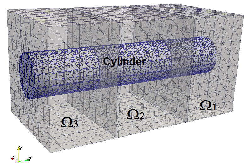
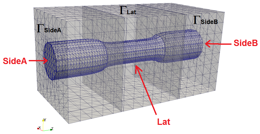
In Figs. 3(a) and 3(b) the mesh structures used in the numerical simulations are reported. The typical number of simplices is in the range of 50000 elements. Channel length is set at while channel diameter is equal to . Channel terminals are restricted to the internal cylinder of the lateral vertical surfaces: the outside structure represents the biological region that is assigned to the constriction or to the dilation of the channel itself. The Z-axis is aligned with the symmetry axis of the structures and is oriented from towards terminals. Cell interior is located at while cell exterior ambient is located at .
7.1. Numerical results for the VE-PNP model
In this case study we investigate the impact of the velocity term in the VE-PNP model at a constant room temperature. Referring to (5) and (8), and according to Tab. 1, Dirichlet boundary conditions for ionic concentrations and electrostatic potential are enforced on (cell-inside) and (cell-outside) surfaces while homogeneous Neumann conditions hold elsewhere. In the Stokes problem (6) Neumann boundary conditions are applied on and , with a pressure drop of whereas homogeneous Dirichlet conditions for fluid velocity hold elsewhere (adherence condition). The initial values are set at and for the ionic concentrations and equal to zero for the electrolyte fluid velocity.
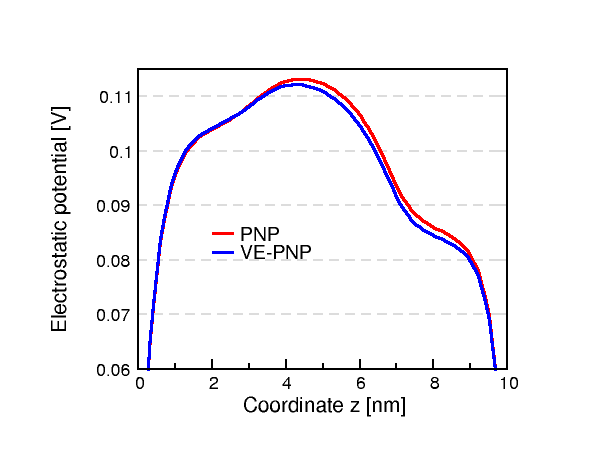
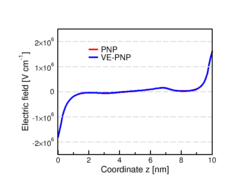
Fig. 4(a) and fig. 4(b) show at time the profile of electrostatic potential and of the component of the electric field obtained along the cylinder symmetry axis for both VE-PNP and PNP-only models. The onset of pronounced bumps in the electrostatic potential is responsible for a nonuniform contribution of the electric field to ion electrodiffusion. As a matter of fact, close to the interior part of the channel drift forces are directed towards cell interior while at the end of the channel the drift forces point outward of the cell. The difference between the prediction of the VE-PNP and PNP models is not so relevant in this case, as confirmed by the fact that the small variations in the potential plot completely disappear in the electric field plot.
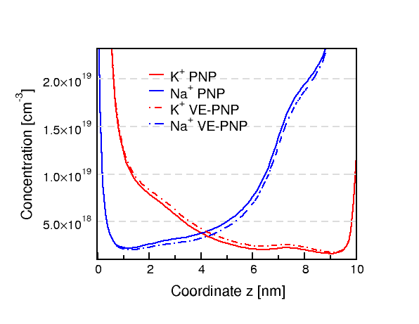
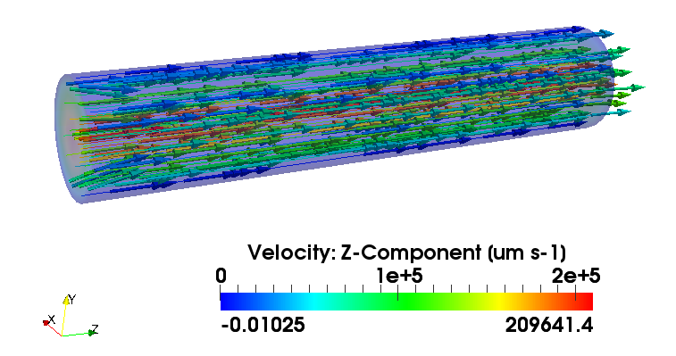
Fig. 5 shows the profile of K+ and Na+ ion concentrations. Since the -component of the electrolyte fluid velocity is positive the K+ species is more diffused towards the positive -axis in the case of the VE-PNP model. Conversely, in the case of Na+ the electrolyte fluid flow causes a reduction of diffusion towards cell interior. The asymmetry in the ionic concentration profiles as shown in fig. 5 is to be ascribed to the cumulative effect of drift and diffusion forces: in fact, close to and drift is opposing to diffusion but K+ ions have a higher diffusion gradient and lower drift force. In fig. 6 a vector field plot of the electrolyte fluid velocity is shown at time : as anticipated, velocity is directed towards the positive -axis due to the imposed boundary conditions.
7.1.1. Validation of the Hughes-Franca-Balestra formulation
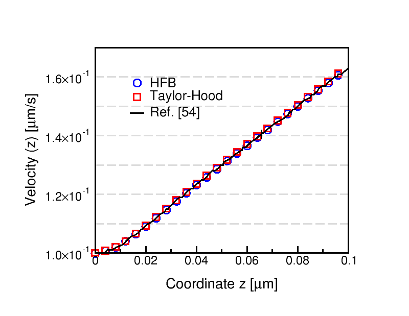
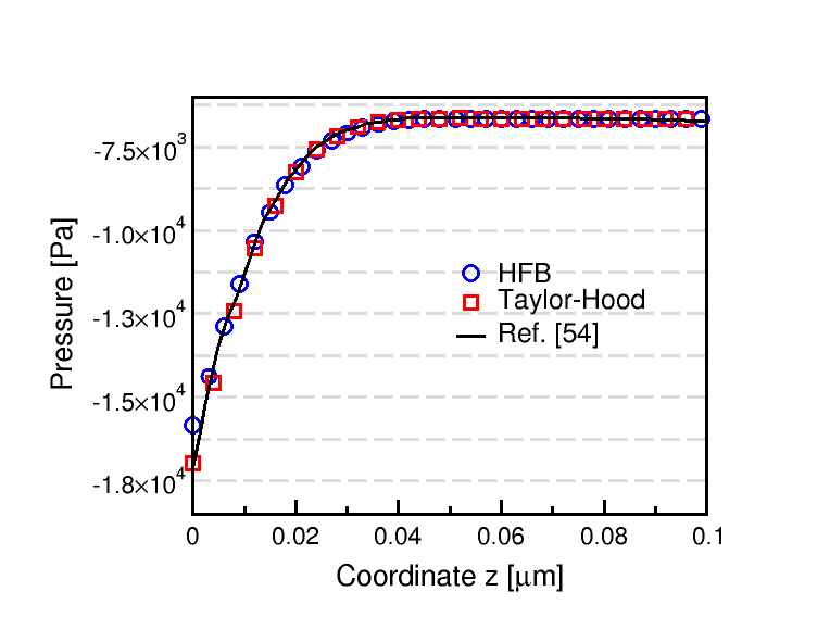
As already pointed out in sec. 6.2 the use of a stabilized finite element space in the discretization of (6) considerably reduces the number of dofs and, as a consequence, the computational cost. The HFB methodology, however, requires an appropriate choice of the stabilization parameter . This issue is documented in the example below. Fig. 7(a) and fig. 7(b) show the velocity and the pressure profiles in a case study on a cylinder of length and of diameter where on the -component of the velocity is set equal to , on the Neumann condition is applied while a no-stress condition is applied on the lateral surface. The numerical solutions obtained using MP-FEMOS with the TH or HFB pairs are indistinguishable from those computed by the commercial software COMSOL [16].
7.2. Effects of a thermal gradient in the VE-PNP model
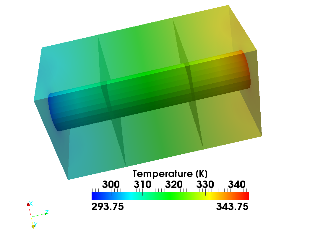
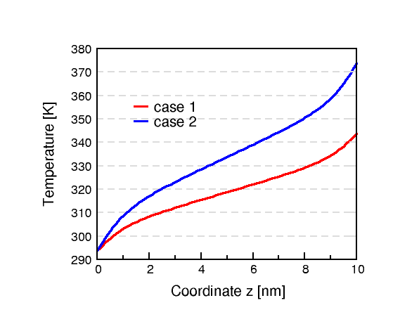
In the context of the numerical simulation of ion migration in phase change materials for electronics applications [45] we have introduced the effect of a thermal gradient in the physical system as a further driving force in the basic electrodiffusion model of ions (2a). In this section we aim to understand the role of such phenomenon in the context of a biological environment. To verify this issue we perform a computational test in which we have deliberately chosen a non-physiological value of the temperature located outside the cell ( terminal). The thermal gradient is consequent result of the following boundary conditions in (11a):
| onBot | |||
| onTop | |||
| onTop | |||
We named the previous conditions as and respectively where we have neglected any heat generation phenomena in (9a). The thermal profiles found inside the ionic channel after the simulation are complicated by the fact that the Dirichlet boundary conditions are applied only on the channel terminals and not on the whole as shown in Figs. 8(a) and 8(b).
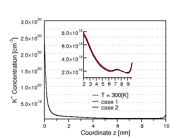
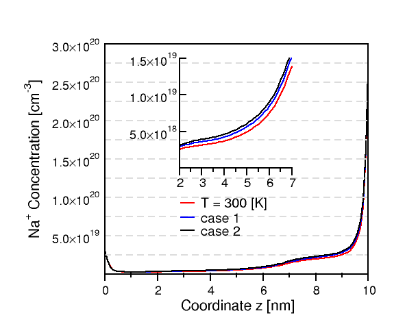
Figs. 9(a) and 9(b) show the effect of the thermal gradient on K+ and Na+ concentration profiles: 1D-cut are at the final time along the geometrical symmetry axis. Black color refers to the constant temperature case , the red color to and the blue to . As the thermal gradient increases, the ionic species are drifted towards the surface, as prescribed by the negative sign in eq. (9a): Na+ is more diffused while K+ is less.
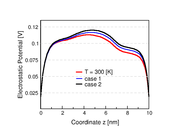
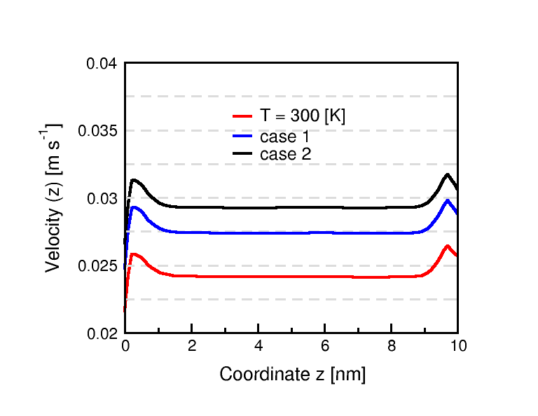
The electrostatic potential, shown in fig. 10(a), is increased in the left part of the channel due to the higher ion concentrations in that region when the thermal gradient is not null. For the same reason the influence of the ionic pressure onto the fluid is more pronounced as shown in fig. 10(b).
From the computational analysis of this section we can conclude that the contribution of a thermal driving force to ionic flow is not relevant in biological systems unlike the case of semiconductor materials illustrated in [45].
7.3. Numerical results for the VE-PNP model considering mechanical stress
In this section we demonstrate the effect on ion electrodiffusion due to the action of external mechanical forces able to modify the size of the biological channel. This aspect of cellular biology is fundamental in many control mechanisms of a living system, for example, heart beat, muscle activity or cerebrovascular autoregulation (see [35] for details and further reference). As discussed in sec. 4, the solution of the mechanical problem (12a) is used to determine the finite element mesh transformation that yields the new domain geometry in which (2) and (6) are solved with a split domain algorithm. The following boundary conditions are applied to solve (12a) where is the lateral surface of the whole parallelepiped, , and are three separate regions with different mechanical properties as reported in Tab. 1.
| (44a) | ||||
| (44b) | ||||
| (44c) | ||||
| (44d) | ||||
| (44e) | ||||
We denote condition (44d) as deformation 1 () while (44e) as deformation 2 (): the case with no deformation is indicated with . An example of deformed mesh obtained after the solution of (12a) in the case of is shown in fig. 3(b). The deformed mesh is obtained by simply stretching each element according to the computed displacement and avoiding the insertion of any new vertex or further mesh refinement.
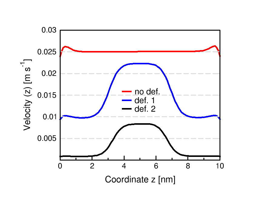
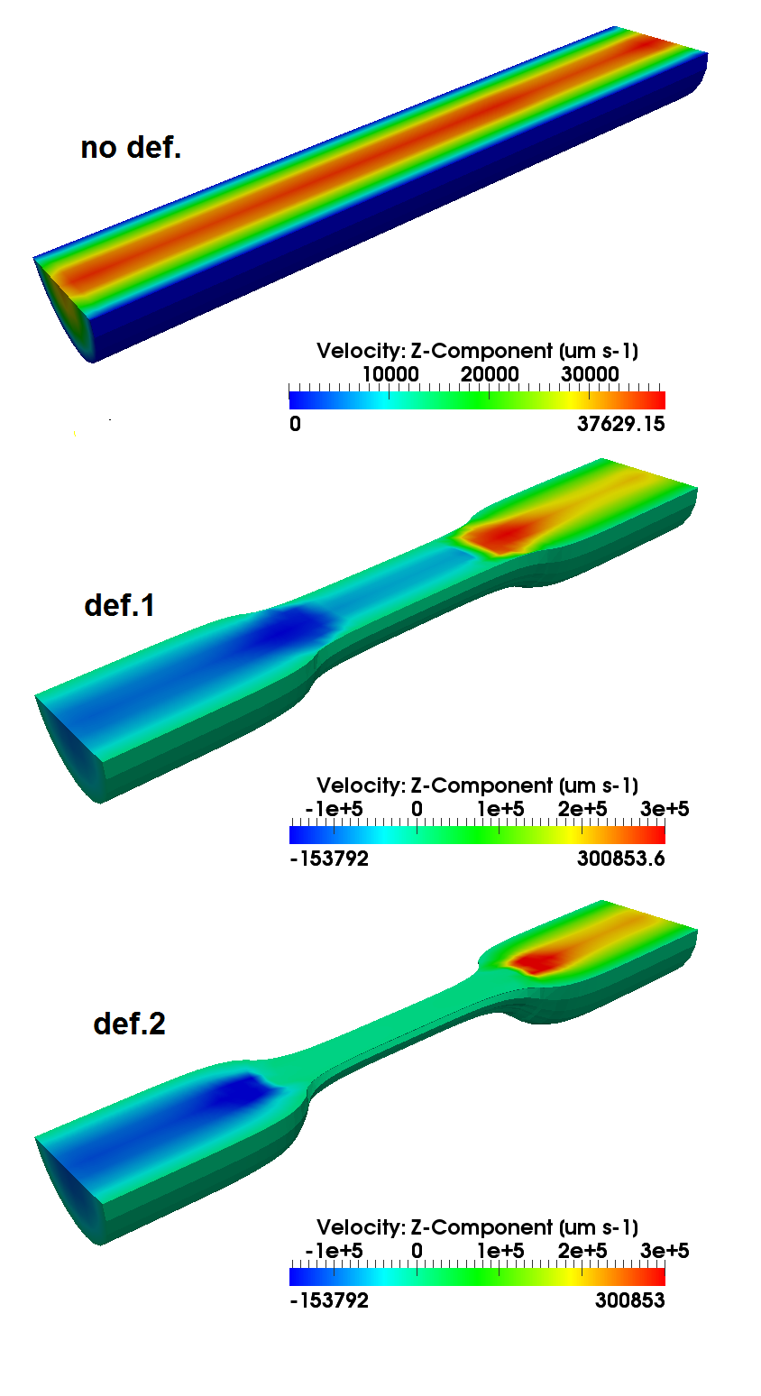
Fig. 11 shows the impact of channel size modification on the fluid velocity profiles (-component) (no-ionic pressure is considered). Results have been obtained by solving only (6) in the deformed domain, with 1D-cut taken along the geometrical symmetry axis. As expected, the average value of the velocity decreases with the increase of deformation, but in the region where the channel is restricted the electrolyte fluid velocity increases.
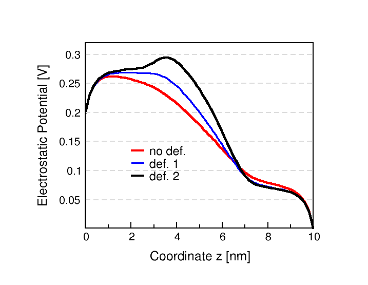
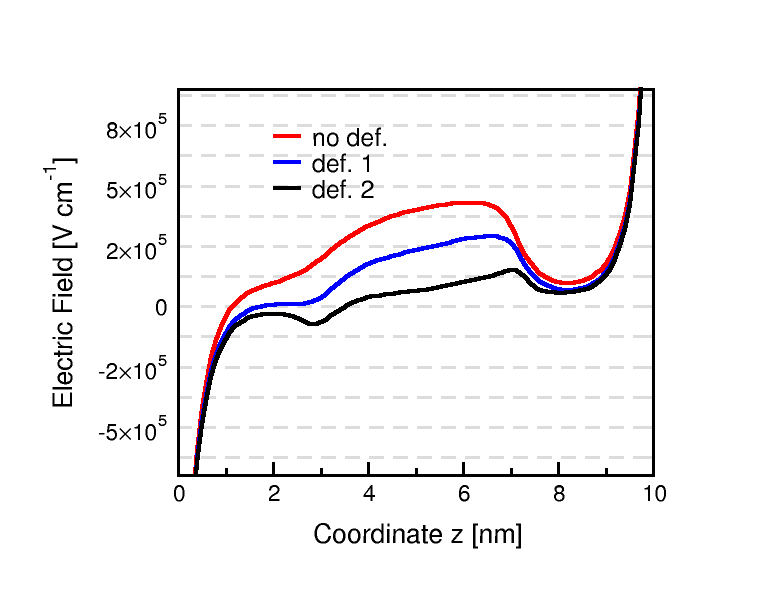
Before describing the ion concentration profiles computed by the VE-PNP model in presence of mechanical forces it is important to look at the profiles of the driving forces acting on ion electrodiffusion. Figs. 12(a) and 12(b) illustrate the electrostatic potential and electric field profiles with and without deformation. Increasing the deformation the electric field strength in the channel center is quite reduced while the region close to where the electric field is negative is extended towards the channel center. In all cases the electric field drop close to corresponds to the almost flat profile in the electrostatic potential.
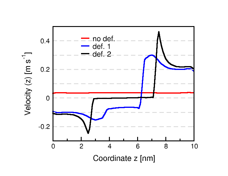
The effects of ionic pressure on the fluid velocity are shown in fig. 13: not only is the velocity not constant in the channel but also it undergoes a change of sign (inversion of electrolyte flow). From the cell-inside to the two third of the channel the velocity is directed towards the cell while in the final part of the channel it moves in the opposite direction. Moreover increasing deformation, a reduction of the velocity at the center of the channel is found due to the reduction of the electric field.
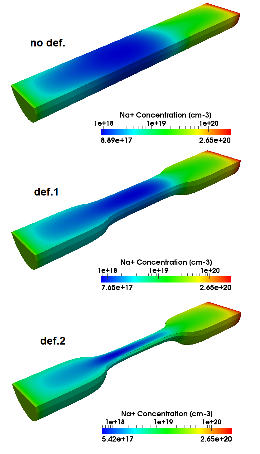
Fig. 14 illustrates the K+ and Na+ concentration profiles. For both species the main variation with respect to the unperturbed channel configuration is obtained in the center portion of the channel but with a remarkable difference.
In the case of K+, Fick’s diffusion is towards the end of the channel as the electric field and velocity in the case of normal size channel. This produces the K+ accumulation at the end of the channel: the Dirichlet boundary condition causes the reduction of the concentration at . With the deformation, fluid velocity becomes negative and is directed towards the cell so that accumulation no longer occurs.
In the case of Na+, Fick’s diffusion is directed towards the cell while the velocity is towards the outside with an increased strength under deformation: this is the reason why the deformed channel has a less diffused profile.
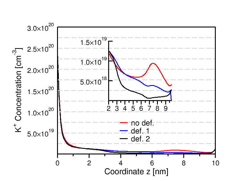
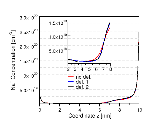
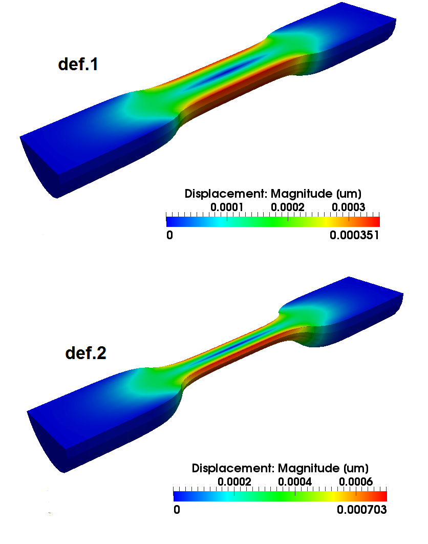
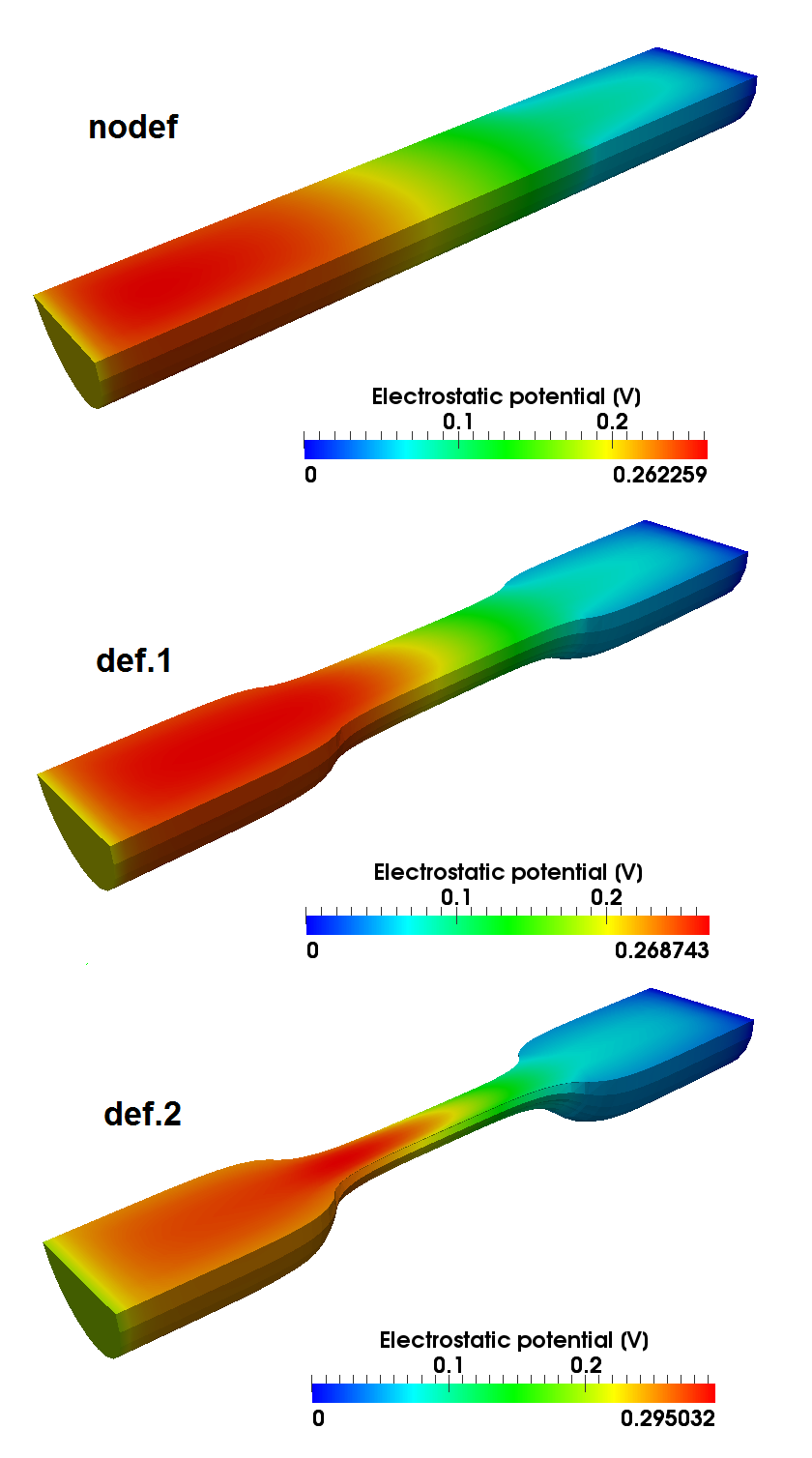
The 3D plots of fig. 15(a) show how the deformation is along the normal direction of the channel axis and it increases with the deformation strength in (44d) and (44e). As a consequence, channel diameter is further and further reduced. Fig. 15(b) shows how the potential profile of 12(a) in a 3D view is uniform across the channel with no peaks induced by the possible accumulation of ionic charge at the channel surfaces. Fig. 16(a) shows the 3D view of the -component of the fluid velocity: the profile across the cell is nonuniform also in the undeformed case due to the adherence condition: the more the deformation, the more the nonuniformity of velocity distribution. Fig. 16(b) illustrates the 3D profile of Na+ ionic concentration. As in the case of electrolyte fluid, the increased channel deformation significantly affects the nonuniformity of the 3D distribution of the sodium ion inside the channel. This effect might be very important in regulating the electrostatic coupling between the mobile charge distribution in the channel and the permanent charge that is usually trapped inside the lipid membrane bilayer surrounding the channel. This biophysical aspect of the problem has been investigated by Prof. W. Nonner and coworkers in [38, 7] and will be object of a future step of our research.
8. Conclusions and Future Perspectives
In this article we have carried out a three-dimensional modeling and simulation, in three spatial dimensions and in time dependent conditions, of biological ion channels using a continuum-based approach. The proposed model is a multi-physics formulation that is capable to combine, to the best of our knowledge for the first time, ion electrodiffusion, channel fluid motion, thermal self-heating and mechanical deformation. The full self-consistency is intended for further study. Here, the thermal and mechanical effects are unidirectional.
The resulting mathematical picture is a system of nonlinearly coupled partial differential equations in conservation form that describes the fundamental principles of ion charge and momentum balance, heat flow balance, electrolyte mass and momentum balance and mechanical balance in the nanochannel.
A functional iteration that decouples the various differential subblocks of the system is introduced with the purpose of facilitating the computational implementation. Then, each resulting subproblem is discretized using the Galerkin Finite Element Method.
The validation of the proposed computational model is carried out by simulating a realistic cylindrical voltage operated ion nanochannel where K+ and Na+ ions are simultaneously flowing. Three sets of numerical experiments are performed and thoroughly discussed. We first investigate the coupling between electrochemical and fluid-dynamical effects. Then, we enrich the modeling picture by investigating the influence of a thermal gradient. Finally, we add a mechanical stress responsible of channel deformation and investigate its effect on the functional response of the channel. Results show that fluid and thermal fields have no influence in absence of mechanical deformation whereas ion distributions and channel functional response are significantly modified if mechanical stress is included in the model. These predictions agree with biophysical conjectures on the importance of protein conformation in the modulation of channel electrochemical properties developed by Prof. W. Nonner and coworkers in [38, 7].
Future extensions to overcome present model/methods limitations include, being not restricted to:
-
•
the coupling between stress and deformation fields and the PNP system to self-consistently calculate the deformation of channel wall;
-
•
a biophysically sound characterization of the heat production term in the thermal block to account the effect of chemical reactions at the entrance of channel mouth between ions and, for example, externally supplied drugs;
-
•
the electrostatic coupling between the mobile charge distribution in the channel and the permanent charge trapped inside the lipid membrane bilayer;
-
•
the extension and analysis of the EAFE formulation to account for electrolyte velocity in the thermo-electrical drift term in the discretization of the T-VE-PNP model.
References
- [1] P. Airoldi, A. G. Mauri, R. Sacco, and J. W. Jerome. Three-dimensional numerical simulation of ion nanochannels. Journal of Coupled System and Multiscale Dynamics, 3(1):57–65, 2015.
- [2] David Attwell, Alastair M. Buchan, Serge Charpak, Martin Lauritzen, Brian A. MacVicar, and Eric A. Newman. Glial and neuronal control of brain blood flow. Nature, 468(7321):232–243, 2010.
- [3] I. Babuska and J. E. Osborn. Generalized finite element methods: Their performance and their relation to mixed methods. SIAM J. Numer. Anal., 20:510–536, 1983.
- [4] V. Barcilon. Ion flow through narrow membrane channels: Part i. SIAM J. Appl. Math., 52(5):1391–1404, 1992.
- [5] V. Barcilon, D. Chen, R. S. Eisenberg, and J. W. Jerome. Qualitative properties of steady-state Poisson-Nernst-Planck systems: perturbation and simulation study. SIAM J. Appl. Math., 57(3):631–648, 1997.
- [6] Victor Barcilon, D.-P. Chen, and R. S. Eisenberg. Ion flow through narrow membrane channels: Part ii. SIAM Journal on Applied Mathematics, 52(5):1405–1425, 1992.
- [7] D. Boda, M. Valiskó, D. Henderson, B. Eisenberg, D. Gillespie, and W. Nonner. Ion selectivity in L-type calcium channels by electrostatics and hard-core repulsion. J. Gen. Physiol., 133:497 – 509, 2009.
- [8] D. Braess. Finite Elements: Theory, Fast Solvers, and Applications in Solid Mechanics. Cambridge University Press, 2001.
- [9] S. Brenner and L.R. Scott. The Mathematical Theory of Finite Element Methods. Texts in Applied Mathematics. Springer New York, 2002.
- [10] F. Brezzi. On the existence, uniqueness and approximation of saddle-point problems arising from lagrangian multipliers. ESAIM: Mathematical Modelling and Numerical Analysis - Modélisation Mathématique et Analyse Numérique, 8(R2):129–151, 1974.
- [11] F. Brezzi, L. D. Marini, and P. Pietra. Numerical simulation of semiconductor devices. Comp. Meths. Appl. Mech. Engrg, 75:493–514, 1989.
- [12] F. Brezzi, L. D. Marini, and P. Pietra. Two-dimensional exponential fitting and applications to drift-diffusion models. SIAM Journal on Numerical Analysis, 26(6):1342–1355, 1989.
- [13] M. J. Caterina, M. A. Schumacher, M. Tominaga, T. A. Rosen, J. D. Levine, and D. Julius. The capsaicin receptor: a heat-activated ion channel in the pain pathway. Nature, 389(6653):816–824, 1997.
- [14] CERFACS, ENS Lyon, INPT(ENSEEIHT)-IRIT, Inria and University of Bordeaux. MUMPS: a parallel sparse direct solver (2015).
- [15] H.C. Chang and L. Yao. Electrokinetically Driven Microfluidics and Nanofluidics. Cambridge University Press, 2009.
- [16] COMSOL. Multiphysics, User guide. 2013.
- [17] G. B. Ermentrout and D. H. Terman. Mathematical Foundations of Neuroscience. Springer, 2010.
- [18] D. D. Friel and R. W. Tsien. A caffeine- and ryanodine-sensitive Ca2+ store in bullfrog sympathetic neurones modulates effects of Ca2+ entry on [Ca2+]i. J Physiol., 450:217–246, 1992.
- [19] E. Gatti, S. Micheletti, and R. Sacco. A new Galerkin framework for the Drift-Diffusion equation in semiconductors. East West Journal of Numerical Mathematics, 6:101–136, 1998.
- [20] D. Gilbarg and N.S. Trudinger. Elliptic partial differential equations of second order. Grundlehren der mathematischen Wissenschaften. Springer, 1998.
- [21] M.Longaretti G.Marino J.W.Jerome, B.Chini and R.Sacco. Modeling and simulation of thermo-fluid-electrochemical ion flowion biological channel. Journal of nanosciences and natechnology, pages 8(7):3686–3694(9), 2008.
- [22] B. Hille. Ionic Channels of Excitable Membranes. Sinauer Associates, Inc., Sunderland, MA, 2001.
- [23] A.L. Hodgkin and A.F. Huxley. Currents carried by sodium and potassium ions through the membrane of the giant axon of loligo. Journal of Physiology, 116:449–472, 1952.
- [24] A.L. Hodgkin and A.F. Huxley. The dual effect of membrane potential on sodium conductance in the giant axon of loligo. Journal of Physiology, 116(4):497–506, 1952.
- [25] A.L. Hodgkin and A.F. Huxley. A quantitative description of membrane current and its application to conduction and excitation in nerve. Journal of Physiology, 117:500–544, 1952.
- [26] A.L. Hodgkin, A.F. Huxley, and B. Katz. Measurement of current-voltage relations in the membrane of the giant axon of loligo. Journal of Physiology, 116(4):424–448, 1952.
- [27] T. J. R. Hughes. The Finite Element Method: Linear Static and Dynamic Finite Element Analysis. Prentice-Hall, 1987.
- [28] T J R Hughes, L P Franca, and M Balestra. A new finite element formulation for computational fluid dynamics: V. circumventing the Babuska-Brezzi condition: A stable Petrov-Galerkin formulation of of the Stokes problem accommodating equal-order interpolations. Comput. Methods Appl. Mech. Eng., 59(1):85–99, 1986.
- [29] M. Hutzler, A. Lambacher, B. Eversmann, M. Jenkner, R. Thewes, and P. Fromherz. High-resolution multitransistor array recording of electrical field potentials in cultured brain slices. Journal of neurophysiology, 96(3):1638–1645, 2006.
- [30] A. Huxley. From overshoot to voltage clamp. Trends in neurosciences, 25(11):553–558, 2002.
- [31] J. W. Jerome. Analysis of charge transport. Springer-Verlag, 1996.
- [32] J. W. Jerome. Analytical approaches to charge transport in a moving medium. Transport Theory and Statistical Physics, 31:333–366, 2002.
- [33] J. W. Jerome and R. Sacco. Global weak solutions for an incompressible charged fluid with multi-scale couplings: Initial-boundary value problem. Nonlinear Analysis, 71:e2487–e2497, 2009.
- [34] O. Kedem and A. Katchalsky. Thermodynamic analysis of the permeability of biological membranes to non-electrolytes. Biochimica et Biophysica Acta, 27:229 – 246, 1958.
- [35] J. P. Keener and J. Sneyd. Mathematical Physiology. Springer, New York, 1998.
- [36] L.D. Landau and E.M. Lifshitz. Fluid Mechanics. Pergamon press, 1959.
- [37] R. A. Levis and J. L. Rae. Technology of patch- clamp electrodes. In A. A. Boulton, G. B. Baker, and W. Walz, editors, Patch-Clamp Applications and Protocols, volume 26 of Neuromethods, pages 1–36. Humana Press, 1995.
- [38] A. Malasics, D. Gillespie, W. Nonner, D. Henderson, B. Eisenberg, and D. Boda. Protein structure and ionic selectivity in calcium channels: Selectivity filter size, not shape, matters. Biochimica et Biophysica Acta (BBA) - Biomembranes, 1788(12):2471 – 2480, 2009.
- [39] P.A. Markowich. The Stationary Semiconductor Device Equations. Computational Microelectronics. Springer-Verlag, 1986.
- [40] P.A. Markowich, C.A. Ringhofer, and C. Schmeiser. Semiconductor Equations. Springer-Verlag, 1990.
- [41] A. .G. Mauri, A. Bortolossi, G. Novielli, and R. Sacco. 3D finite element modeling and simulation of industrial semiconductor devices including impact ionization. Journal of Mathematics in Industry, 5:1–18, 2015. doi:10.1186/s13362-015-0015-z.
- [42] A. G. Mauri, R. Sacco, and M. Verri. Electro-thermo-chemical computational models for 3D heterogeneous semiconductor device simulation. Applied Mathematical Modelling, 39(14):4057–4074, 2014.
- [43] E. Neher and B. Sakmann. The patch clamp technique. Scientific American, 266(3):44–51, 1992.
- [44] E.A. Newman. Functional hyperemia and mechanisms of neurovascular coupling in the retinal vasculature. J Cereb Blood Flow Metab, 33(11):1685–95, 2013.
- [45] G. Novielli, A. Ghetti, E. Varesi, A. G. Mauri, and R. Sacco. Atomic migration in phase change materials. In Electron Devices Meeting (IEDM), 2013 IEEE International, pages 22.3.1–22.3.4, Dec 2013.
- [46] J. H. Park and J. W. Jerome. Qualitative properties of steady-state Poisson-Nernst-Planck systems: mathematical study. SIAM J. Appl. Math., 57(3):609–630, 1997.
- [47] A. Quarteroni, R. Sacco, and F. Saleri. Numerical Mathematics. Texts in Applied Mathematics. Springer, 2007.
- [48] A. Quarteroni and A. Valli. Numerical Approximation of Partial Differential Equations. Springer-Verlag, 1997.
- [49] I. Rubinstein. Electrodiffusion of Ions. SIAM, Philadelphia, PA, 1990.
- [50] F. Sachs. Stretch-activated ion channels: What are they? Physiology, 25(1):50–56, 2010.
- [51] D.L. Scharfetter and H.K. Gummel. Large signal analysis of a silicon Read diode oscillator. IEEE Trans. Electron Devices, ED-16(1):64–77, 1969.
- [52] M. Schmuck. Analysis of the Navier-Stokes-Nernst-Planck-Poisson system. Mathematical Models and Methods in Applied Sciences, 19(6):993–1015, 2009.
- [53] S. Selberherr. Analysis and Simulation of Semiconductor Devices. Springer-Verlag, 1984.
- [54] B. Straub, E. Meyer, and P. Fromherz. Recombinant maxi-k channels on transistor, a prototype of iono-electronic interfacing. Nat Biotech, 19(2):121–124, 2001.
- [55] R.S. Varga. Matrix Iterative Analysis. Springer Series in Computational Mathematics. Springer Berlin Heidelberg, 1999.
- [56] I. Vlassiouk and Z.S. Siwy. Nanofluidic diode. Nano Letters, 7(3):552–556, 2007.
- [57] T. Voets, G. Droogmans, U. Wissenbach, A. Janssens, V. Flockerzi, and B. Nilius. The principle of temperature-dependent gating in cold- and heat-sensitive TRP channels. Nature, 430(7001):748–754, 2004.
- [58] J. Xu and L. Zikatanov. A monotone finite element scheme for convection-diffusion equations. Mathematics of Computation, 68:1429–1446, 1999.
- [59] G. Zeck and P. Fromherz. Noninvasive neuroelectronic interfacing with synaptically connected snail neurons immobilized on a semiconductor chip. Proceedings of the National Academy of Sciences, 98(18):10457–10462, 2001.