Fano resonances and band structure of two dimensional photonic structures
Abstract
We show that the frequency spectrum of two dimensional photonic crystals is strongly influenced by Fano resonances which can be excited already in the linear array of dielectric cylinders. To support this claim, we calculate the transmission of electromagnetic wave through linear array of dielectric cylinders and show that frequencies of observed Fano resonances coincides with position of narrow frequency bands found in the spectra of corresponding two-dimensional photonic crystals. Split of frequency band or overlap of two bands, observed in the band structure of photonic structures are also associated with Fano resonances.
pacs:
42.70.QsI Introduction
Frequency spectrum of photonic crystals consists of large number of continuous bands. This is a direct consequence of spatial periodicity of the permittivity which defines the structure. In the limit of infinitesimally small variations of the permittivity, all frequency bands could be constructed from the dispersion relation of electromagnetic wave in homogeneous medium by reduction of the momenta to the first Brillouin zone sakoda ; costas ; iok . With increasing permittivity contrast, frequency gaps open at the edges of Brillouin zone joan-pc . We will call the resulting frequency bands periodic () bands.
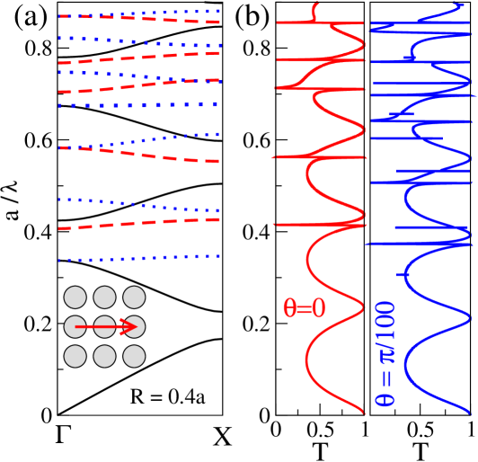
For higher permittivity contrast, the frequency spectrum is more complicated. It contains, besides the bands, also other, usually very narrow (almost dispersionless) frequency bands. As an example, we show in Fig. 1(a) the frequency spectrum of two dimensional square array of dielectric cylinders embedded in vacuum. Only five of 17 displayed frequency bands are bands.
The aim of this Paper is to explain physical origin these additional frequency bands. We prove that they originate from Fano resonances fano ; miro which can be excited in linear chain of dielectric cylinders by incident electromagnetic wave. We find numerically the spectrum of these resonances and demonstrate how each resonance develops into narrow Fano () band in corresponding two-dimensional photonic crystal.
The band structure shown in Fig. 1(a) was calculated for the square array of thick dielectric cylinders. For other structures, for instance photonic crystals composed from thinner cylinders, mutual coupling of and original band occurs which results in irregularities of the band spectrum. Two of them, namely the split of the band, and an overlap of two bands, will be discussed later.
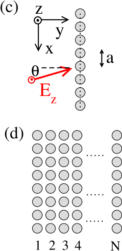
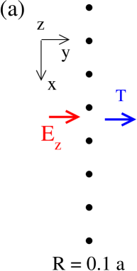
Fano resonances in photonic structures sfan were studied mostly in process of interaction of two dimensional photonic slabs with incident electromagnetic wave fan and were used for experimental identification of spectra of leaky modes in photonic structures astr . For the case of individual dielectric cylinder, Fano resonances were observed as a result of the coupling of Mie resonant states mie ; hulst with an incident electromagnetic wave in spherical trib and cylindrical dielectric object rybin . Fano resonances play an important role in design of metamaterials rr ; luk and influence considerably the transport properties of disordered systems fano-nature . Here, we are interested in Fano resonances which could be excited by plane electromagnetic wave incident to the linear periodic array of dielectric cylinders (Fig. 1(c)) as a result of interference of leaky guided modes of periodic array of cylinders joan-pc with incident electromagnetic wave. These resonances can be characterized by the resonant frequency and lifetime which is inversely proportional to the width of the resonant peak. Surprisingly, they are narrower than resonances excited in individual dielectric cylinders. If the electromagnetic wave propagates across chains of cylinders (Fig. 1(d)) then resonances excited in individual chains couple together and create narrow transmission band obtained in the frequency spectra of photonic crystals.
II Structure and method
We concentrate on periodic photonic structures composed from dielectric cylinders parallel to the axis. Cylinders possess a frequency independent permittivity and permeability . The embedding medium is vacuum. Radius of cylinders is and the distance between two nearest-neighbor cylinders is .
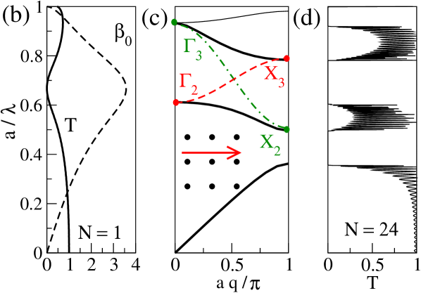
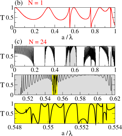
The first structure is the linear chain of dielectric cylinders lying in the axis (Fig. 1(c)). Incident electromagnetic wave of wavelength excites in this structure Fano resonances which manifests themselves as sharp irregularities in the frequency dependence of the transmission coefficient visible in Fig. 1(b). Transmission coefficient is calculated also for finite photonic slab constructed from rows of the same cylinders located in planes (, see Fig. 1(d)). Observed transmission spectra will be compared with the band structure of an infinite square array of cylinders calculated by plane wave expansion method sakoda .
Transmission coefficient is calculated by the transfer matrix method pendry ; pre . For more detailed analysis of the spatial distribution of electric field, we use another algorithm based on the expansion of electromagnetic field into cylinder functions hulst ; stratton ; on ; oua . If an incident electromagnetic wave is polarized with electric field parallel to cylinders (this polarization is considered throughout this Paper) then the intensity of electric field scattered at a cylinder centered in can be expressed as
| (1) |
for and , respectively. Similar expressions for radial and tangential components of magentic field could be derived from Maxwell equations stratton . In Eq. (1), , , pozn , are Bessel and Hankel function, determines the wavelength of electromagnetic field in vacuum and is the index of refraction.
For another cylinder, centered at and the field is again expressed by Eq. 1 but with new set of coefficients , and cylindrical coordinates and associated with the center of the cylinder.
In numerical simulations, we calculate coefficients and from the requirement of continuity of tangential components of the intensity of electric and magnetic field at the boundary of cylinders. Note that spatial periodicity of the structure along the direction considerably reduces the number of unknown coefficients since coefficients and fulfill the Bloch theorem
| (2) |
where is the transverse component of the wave vector. This enables us to reduce the number of unknown coefficients to , where is the highest order of Bessel function used in numerical calculations ( in most cases). To find the transmission coefficient , Poynting vector is calculated on the opposite side of the structure. Details of the method are given elsewhere pm-15 .
| bands: | 1st | 2nd | 3rd | 4th | 5th |
|---|---|---|---|---|---|
|
|
|
|
|
|
| bands: | |||||
|
|
|
|
|
III Results
(e)
 X3
X3 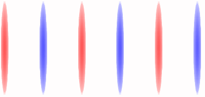
 X2
X2 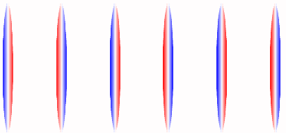
III.1 Isolated Fano bands
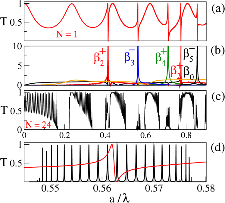
Consider first an array of thick dielectric cylinders with radius . Figures 1(b) and 2(a) shows the transmission coefficient of plane electromagnetic wave propagating through linear chain of cylinders. A series of very narrow resonances could be identified. Similar maxima and minims has been found numerically in the reflection coefficient on . Following fan we interpret these resonances as Fano resonances which results from the interference of incident plane wave with leaky guided modes excited in the periodic cylinder row joan-pc . Indeed, these Fano resonances are accompanied by sharp maxima of coefficients defined in Eq. 1 (Figure 2(b)). More detailed analysis of resonances is given in Sect. IV.
Comparison of Figures 1(a) and (b) confirms that Fano resonances develop to narrow Fano bands in the spectra of 2D structures. This is also shown in Figs. 2(c,d) which present the frequency dependence of the transmission coefficient of plane wave propagating through the slab composed from rows of cylinders.
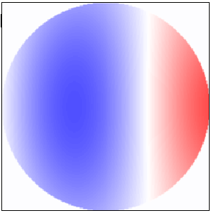
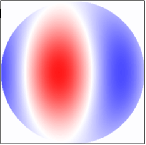
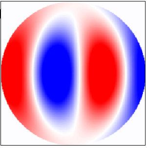
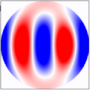
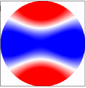
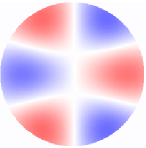
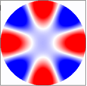
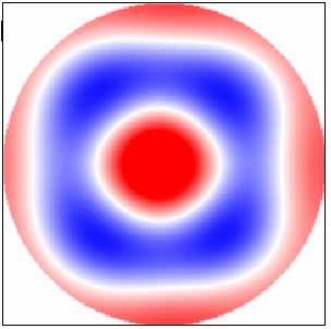
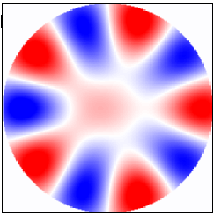
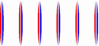
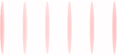
Different character of and bands is clearly visible from the spatial symmetry of the electric field shown in Fig. 3. The top panel displays the field for frequencies chosen in the center of five lowest band shown in Fig. 2(c). As expected, the field symmetry changes when the frequency increases from one frequency band to the next one sakoda ; joan-pc . The bottom panel shows the field for the five lowest resonant frequencies identified in Fig. 2(b). As shown in Fig. 2(d), these frequencies correspond to the center of bands. The symmetry of the field is unambiguously determined by the order of excited Fano resonance.
III.2 Overlap of two bands
For thinner cylinders, the band and the band can overlap. Then, the resulting frequency spectrum depends on the -dependence of the frequency in two bands and on the strength of their mutual coupling. Consider a simple model of two bands and , (centered at the same frequency for simplicity) coupled together with coupling constant . Resulting spectrum has a form
| (3) |
Two bands and are separated by gap if . This happens either when is large or when one of two bands is narrow.
Band splitting. We found the above mentioned band splitting in the frequency spectrum of the square array of thin () dielectric cylinders (Fig. 4). The transmission coefficient through a linear chain of cylinders (Fig. 4(b)) decreases to zero for the frequency . This decrease is accompanied by an increase of coefficient (Eq. 1). We interpret this decrease of the transmission as a result of excitation of broad Fano resonance.
Figure 4(c) shows the band structure of the square array of thin cylinders. Note that both the second and the third bands have a minimum at the X point. These two bands result from the coupling of the band with broad band displayed by dot dashed (X) and dashed (X3) lines, respectively.
This statement is supported also by the analysis of the spatial symmetry of electric field within two bands shown in Fig. 4(e). Note that the symmetry of electric field changes along the line X. Also, the field in points X2 and have the same symmetry; of course, the same holds for pair X3 and . While the field at X2 and possesses the symmetry of the band, field close to inner band edges X3 and has a symmetry of excited Fano resonance.
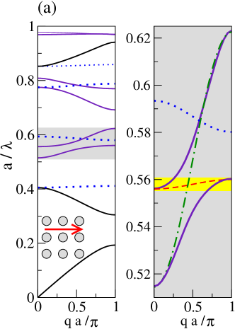
Band overlap. The overlap of and bands is observed in the band structure of the infinite square array of cylinders with radius displayed in Fig. 5(a) As shown in the right panel, the overlap of the 3rd and 4th bands can be interpreted as a result of coupling of two bands shown by dot dashed and dashed lines, respectively. This overlap can be identified also from the complicated frequency dependence of the transmission coefficient sakoda-1997 shown in Fig. 5(b) for the slab of rows of cylinders. Similar analysis could be done for the overlap of the 5th and 6th bands in Fig. 5(a).xx
IV Fano resonance
In previous Section, we have shown that Fano resonances excited in linear array of dielectric cylinders create the bands in spectra of photonic crystals. Now we will discuss physical origin of Fano resonances.
Fano resonances have been observed recently in the most simple dielectric structure – the single dielectric cylinder rybin . If the frequency of incident electromagnetic wave coincides with the eigenfrequency of any cylinder leaky eigenmode, the last can be excited. Then, the electromagnetic field in the neighbor of the cylinder is given by a superposition of two fields with the same frequency: the incident plane wave and field radiated by excited resonance rybin . The excitation of resonance manifests itself as a maximum of coefficient shown in Fig. 6(a). The width of the resonance is proportional to inverse of its lifetime. Similarly, excitation of resonant guided mode in linear array of cylinders can be identified from sharp maxima in frequency dependence of corresponding coefficient (Figs. 2(b), 6(b)). The interference of two modes is the responsible for narrow maxima and minima in the transmission coefficient of incident electromagnetic wave displayed for instance in Figs. 1(b) and 2(a).
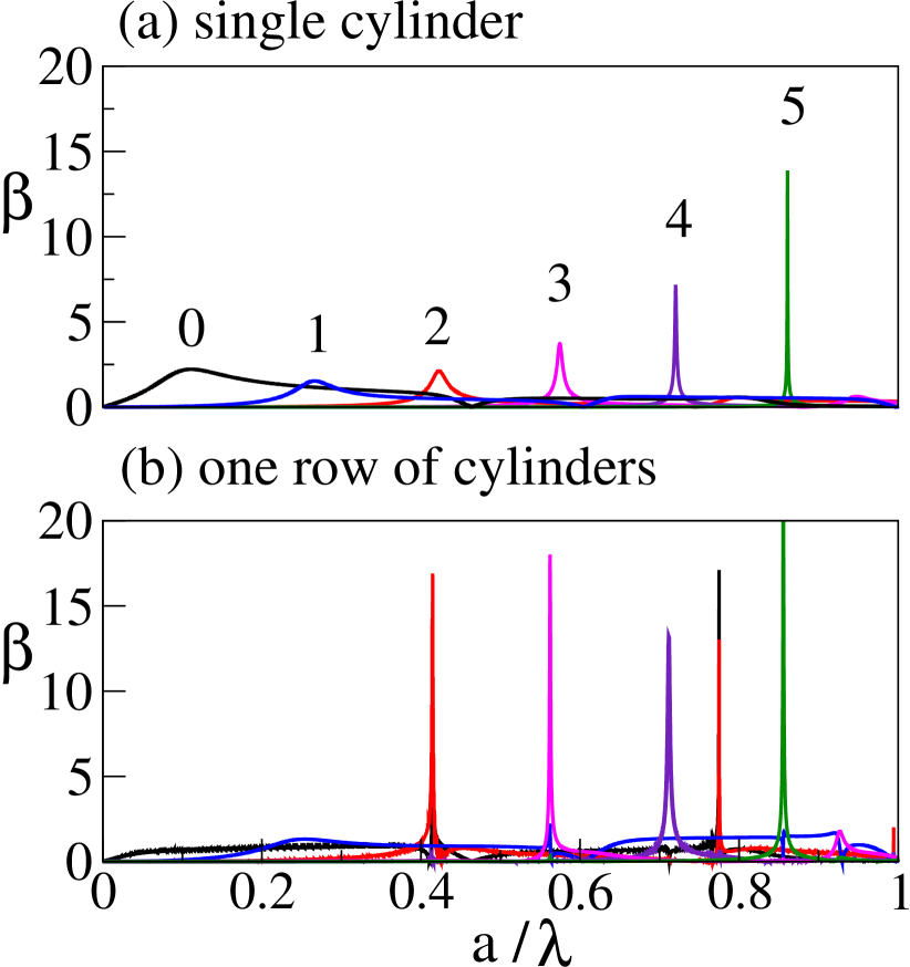

We start with the comparison of the frequency dependence of coefficients for isolated dielectric cylinder (Fig. 6(a) ) and for an infinite periodic array of cylinders (Figs. 2(b) and 6(b)). For single cylinder and polarization, is a solution of system of linear equations stratton
| (4) |
where , is an impedance, and the r.h.s is given by the expansion of incident plane wave into Bessel functions as
| (5) |
As shown in Fig. 6(a), Fano resonances of cylinder lye very close to those of an array of cylinders (Figs. 2(b) and Fig. 6(b)). The first two resonances ( and are relatively broad, especially for an infinite number of cylinders.
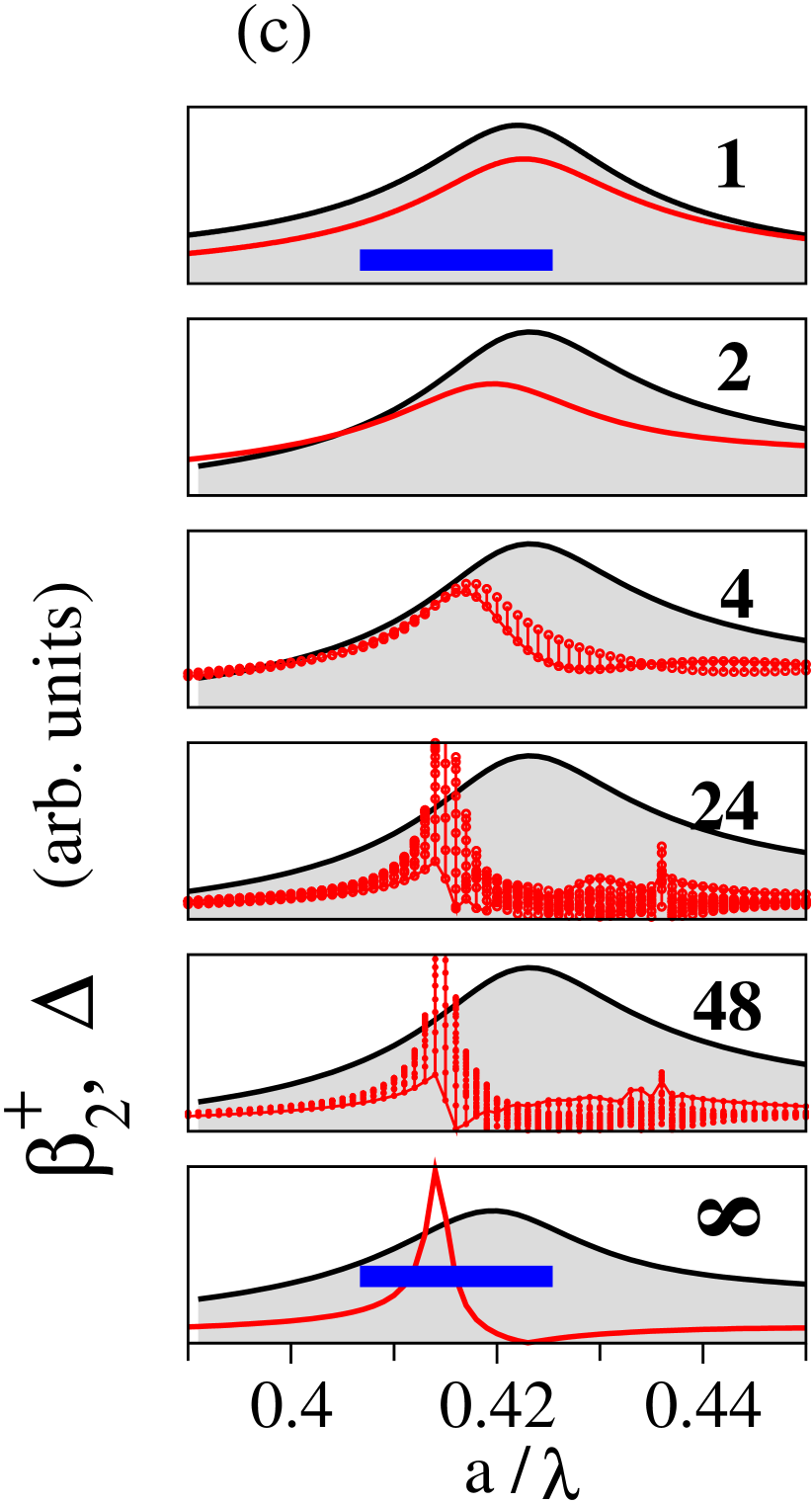
On the other hand, Fano resonances with are significantly narrower when excited in an infinite linear chain of cylinders than in individual cylinder. To explore how the shape of the resonance depends on the number of cylinders, we analyze the scattering of incident electromagnetic wave on finite cluster consisting from cylinders along the direction (Fig. 1(c)). Coefficients were calculated as a solution of system of linear equations
| (6) |
where A is a matrix of the size and vector represents incident electromagnetic wave. Figure 6(c) presents coefficients for finite cluster of cylinders excited by perpendicularly incident plane wave. The resonance indeed becomes narrower when number of cylinders increases. Since the spatial distribution of electromagnetic field along the finite cluster is not homogeneous, acquires various values for individual cylinders inside the cluster. As an example, we plot in Fig. 6(d) spatial distribution of as well as its real and imaginary part calculated in cluster of 48 cylinders.
Figure 6(c) shows also the frequency dependence of an inverse of the determinant of the matrix A (Eq. 6) which determines the eigenfrequencies and lifetimes of leaky guided modes economou exited in the cluster. Comparison of the frequency dependence of an inverse determinant and confirms Fano character of observed excitation and enables to estimate the sign of the Fano parameter miro ; p2 .
V Absorption
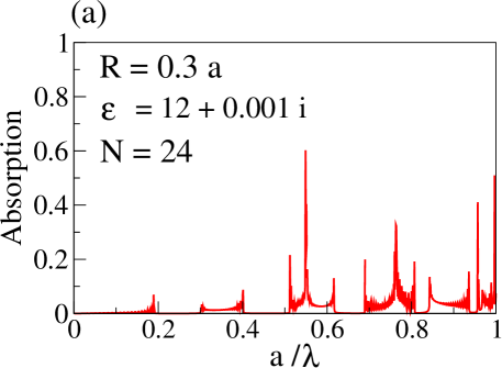
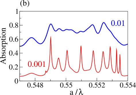
Finally, we note an another difference between and bands: we expect that the bands are much more sensitive to the absorption loses than the bands. One reason is that typical band is narrow, therefore the group velocity of transmitted wave is small. However, more important is that bands are associated with the resonance which led to higher intensity of propagating electric field. Figure 7 presents the absorption of electromagnetic field in the array of cylinders with small imaginary part of the permittivity. Fano bands could be identified from the position of large maxima of the absorption. Note that very small imaginary part of the permittivity (Imag /Real ) causes the absorption of 20% of energy when wave propagates through an array of 24 rows of cylinders.
VI Conclusion
In conclusion, we showed that the band structure of square arrays of cylinders can be completely described in terms of two kinds of frequency bands. The bands originates from the reduction of the dispersion relation to the first reduced zone. The bands have origin in Fano resonances observed in the linear chain of cylinders. The field distribution in bands is determined by the symmetry of Fano resonance. Two bands, and might overlap, which complicates resulting band structure. Since resonance is typically accompanied by strong electric field, we expect that absorption is stronger in bands than in the bands.
This work was supported by the Slovak Research and Development Agency under the contract No. APVV-0108-11 and by the Agency VEGA under the contract No. 1/0372/13.
References
- (1) K. Sakoda, Optical Properties of Photonic Crystals, Berlin, Heidelberg: Springer (2005).
- (2) C. M. Soukoulis (Editor), Photonic Crystals and Light Localization in the 21st Century, NATO Sci. Ser. C.: Mathematical and Physical Sciences 563 Kluwer Acad. Publ. (2001).
- (3) K. Inoue and K. Ohtaka (Editors), Photonic Crystals: Physics, Fabrication and Application, Springer (2010).
- (4) J. D. Joannopoulos, S. G. Johnson, J. N. Winnand R. G. Meade, Photonic Crystals: Molding the Flow of Light 2nd edition. Princeton: Princeton University Press (2008).
- (5) U. Fano, Phys. Rev. 124, 1866 (1961).
- (6) A. E. Miroshnichenko, S. Flach andf Y. S. Kivshar, Rev. Mod. Phys. 82, 2257 (2010).
- (7) S. Fan, W. Suh and J. D. Joannopoulos, J. Opt. Soc. Amm. A 20, 569 (2003).
- (8) S. Fan and J. D. Joannopoulos, Phys. Rev. B 65, 235112 (2002).
- (9) V. N. Astratov, I. S. Culshaw, R. M. Stevenson, D. M. Whittaker, M. S. Skolnick, T. F. Krauss and R. M. De La Rue, J. Light. Technol. 17, 2050 (1999).
- (10) G. Mie, Ann. Physik 25, 377 (1908).
- (11) H. C. van de Hulst, Light scattering by small particles Dover Publ. Inc, NY (1981)
- (12) M.I. Tribelsky, S. Flach, A. E. Miroshnichenko, A.V. Gorbach and Y. S. Kivshar, Phys. Rev. Lett. 100, 04903 (2008).
- (13) M. V. Rybin, K.B. Samusev, I. S. Sinev, G. Semouchkin, E. Semouchjina, Y. S. Kivshar, M. F. Limonov, Optics Express 21, 30107 (2013);
- (14) M. V. Rybin, D. S. Filonov, P.A. Belov, Y. S. Kivshar and M. F. Limonov, Sci. Rep. 5, 8774 (2015).
- (15) B. Lukyanchuk, N. I. Zheludev, S. A. Maier, N. J. Halas, P. Nordlander, H. Giessen and Ch. T. Chong, Nature Materials 9, 707 (2010).
- (16) A. N. Poddubny, M. V. Rybin, M. F. Limonov and Y. S. Kivshar, Nature Communications 3, 914 (2012).
- (17) K. Inoue and K Ohtaka, in iok p. 9.
- (18) M. V. Rybin, A. B. Khanikaev, M. Inoue, K. B. Samusev, M. J. Steel, G. Yushin and M. F. Limonov, Phys. Rev. Lett. 103, 023901 (2009).
- (19) J. B. Pendry and A. MacKinnon, Phys. Rev. Lett. 69, 2772 (1992).
- (20) P. Markoš and C. M. Soukoulis, Phys. Rev. E 65, 036622 (2002).
- (21) J. A. Stratton, Electromagnetic Theory (New York: Mc Graw-Hill Comp. 1941).
- (22) K. Ohtaka, H. Numata, Phys. Lett. 73A, 411 (1979).
- (23) K. Ohtaka, T.Ueda and K. Amemiya, Phys. Rev. B 57, 2550 (1998).
- (24) To assure the numerical stability, Hankel functions are normalized by the frequency-dependent function . Consequently, this function scales coefficients shown in Figures throughout the paper.
- (25) P. Markoš, ArXiv:1501.05125 (unpublished).
- (26) W. M. Robertson, G. Arjavalingam, R. D. Meade, K. D. Brommer, A. M. Rappe and J. D. Joannopoulos, Phys. Rev. Lett. 68, 2023 (1992).
- (27) K. Sakoda, Phys. Rev. B 52, 7982 (1995).
- (28) K. Sakoda, J. Opt. Soc. A. B 14, 1961 (1997).
- (29) Note that the overlap frequency interval, found by the the transfer matrix method in Fig. 5(c) differs slightly from that calculated by the plane wave expansion (Fig. 5(a). The origin of this discrepancy lies in the numerical limitation of the transfer matrix method due to the finite discretization of space.
- (30) M. Abramowitz and I. A. Stegun, Handbook of Mathematical Functions Dover Publ. (1965).
- (31) C. A. Pfeiffer, E. N. Economou and K. L. Ngai, Phys. Rev. B 10, 3038 (1974).
- (32) Note that equals to scattering efficiency rr multiplied by analytic contiguous function of the frequency.