The impact of nuclear spin dynamics on electron transport through donors
Abstract
We present an analysis of electron transport through two weakly coupled precision placed phosphorus donors in silicon. In particular, we examine the (1,1)(0,2) charge transition where we predict a new type of current blockade driven entirely by the nuclear spin dynamics. Using this nuclear spin blockade mechanism we devise a protocol to readout the state of single nuclear spins using electron transport measurements only. We extend our model to include realistic effects such as Stark shifted hyperfine interactions and multi-donor clusters. In the case of multi-donor clusters we show how nuclear spin blockade can be alleviated allowing for low magnetic field electron spin measurements.
I Introduction
An understanding of electron transport through multiple quantum dots has enabled the progression of semiconductor quantum information protocols from single shot spin readout to two-qubit logic gates Johnson et al. (2005); Koppens et al. (2005, 2006); Nowack et al. (2011). Not only do transport measurements provide us with important details on spin relaxation times and tunnel rates, but they play a vital role in aiding our understanding of the complex spin dynamics that occur in these systems, such as coherent manipulation of the electron spins Koppens et al. (2005); Petta et al. (2005) and dynamical nuclear polarisation of the Overhauser field Schuetz et al. (2014).
With recent advances in the fabrication of precision placed donors in silicon Prati et al. (2012); Gonzalez-Zalba et al. (2014); Fuechsle et al. (2012); Weber et al. (2012); Buch et al. (2013) research in this field is now focused on spin transport through multi-donor chains. A deeper understanding of the interplay between electron- and nuclear-spins in the dynamics of such systems is a prerequisite for the progression of this field. In particular for the implementation of spin transport via donor chains Hollenberg et al. (2006). So far, protocols based on spin-chains Bose (2003, 2007); Kay (2010), coherent tunneling adiabatic passage (CTAP) Hollenberg et al. (2006); Rahman et al. (2009, 2010), spin shuttling Cirac and Zoller (2000); Skinner et al. (2003) and SWAP-gate operations Loss and DiVincenzo (1998) have been proposed, all of which require control of electron spin transport across donors. In order to further investigate these transport protocols it is crucial to understand the spin dynamics at the two donor level. However, despite the plethora of theoretical knowledge on gate-defined semiconductor double quantum dots van der Wiel et al. (2003); Taylor et al. (2007); Hanson et al. (2007); double donor transport has not received as much attention.
In this paper we show how the interplay between the electron and nuclear spins in donor-based systems affects not only the charge transport, but also the spin transport. To understand the impact of these nuclear spins we use a master equation approach to conduct a comprehensive numerical analysis of electron transport through a double donor system. We investigate electron spin resonance (ESR) combined with Pauli spin blockade (PSB) at low and high magnetic fields to manipulate and readout the electron spin states. Our most striking finding demonstrates that the presence of the quantised nuclear spin of the donors leads to a novel effect called nuclear spin blockade. Using this mechanism we propose a new spin readout protocol for the nuclear spins based on a measurement of the transport current. Finally, we analyse more realistic scenarios of inhomogeneous hyperfine interactions across the donors, as well as the case of multi-donor dots, which can be shown to be immune to nuclear spin blockade. Throughout the paper we neglect the dynamical behavior of the surrounding 29Si nuclear spins present in natural silicon. This interaction is much smaller than the donor hyperfine interaction Schliemann et al. (2003) and it has also been shown that Si:P devices can be fabricated in isotopically pure 28Si where the absence of the 29Si extends the electron coherence times Muhonen et al. (2014).
II Transport at the (1,1) to (0,2) charge transition
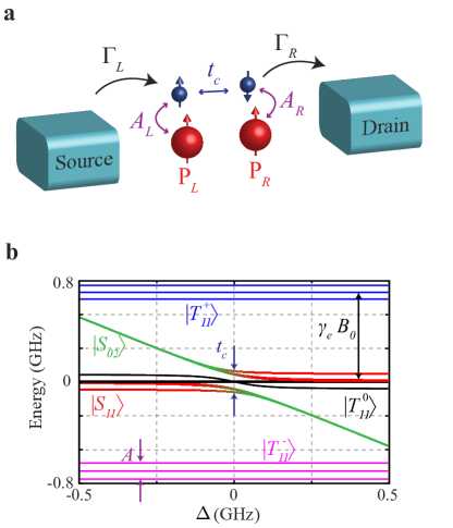
We consider two weakly coupled phosphorus donors in a silicon lattice (approximately 15–20 nm apart Koiller et al. (2002); Wellard et al. (2003)), PL and PR the left and right donor, respectively. Electrons are able to tunnel from in plane source to drain leads via both donors as shown schematically in Fig. 1a. Describing the system is the Hamiltonian ,
| (1) |
where and are the electron and nuclear Zeeman terms, is the tunnel coupling between the donor electrons, is the energy detuning of the state (singlet state with two electrons on a single donor nuclei) and is the hyperfine interaction, for further details see Methods. Throughout the paper we refer to the Hamiltonian in the singlet-triplet basis of the electrons with energies shown in Fig. 1b. By making a transformation from Hilbert space to Liouville space we incorporate incoherent processes that occur during spin transport Ernst et al. (1987). In doing so, tunnelling that occurs from the source at the rate , to the donors and through to the drain at the rate , are integrated with the coherent evolution of the system. Using this approach we can determine the spin and charge dynamics of the donor system during electron transport.
As a first demonstration of the effect of quantised nuclear spin states we study the electron transport from drain to source (reverse of Fig. 1a). In this scenario the charge cycle is (0,1)(0,2)(1,1)(0,1), where (, ) corresponds to the electron numbers on the left and right donor nuclei. In the case of quantum dots it has been shown that the current, , as a function of the detuning, , is given by a known expression involving the coherent and incoherent tunnel rates Nazarov (1993),
| (2) |
where is the electron charge and is the tunnel coupling between the two dots. However, without an external magnetic () dependence, this equation will not account for any spin dynamics. In the case of donors, the measurable current is given by (1,1), where (1,1) is the probability of being in any (1,1) charge configuration, including the electron triplet states .
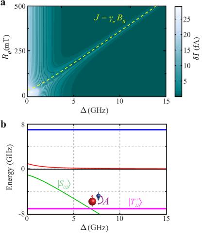
To investigate the effect the inclusion of these states has on electron transport we plot the difference in current, , for in Fig. 2a. There is a peak in the current that can be seen to follow the point at which the electron exchange interaction, , ( GHz) is equal to the electron Zeeman energy, . This is analogous to the canonical spin-funnel experiments Petta et al. (2005). At this value of detuning the hyperfine interaction mixes electron singlet-triplet states via a nuclear spin flip, see Fig. 2b. This increase in the (1,1) state population allows for the electron on PL to tunnel off to the source giving rise to a larger current. In gate-defined quantum dots this current peak is not observed since the large nuclear spin bath has a distribution of hyperfine strengths. Therefore, the position of this peak shown in Fig. 2a, will shift depending on the exact nuclear spin configuration and will be averaged out due to the fluctuating Overhauser field Jouravlev and Nazarov (2006).
For transport across the donors becomes energetically unfavourable as the electrons will remain in the (1,1) region without first loading into the (0,2) charge state, see Fig.1b. We therefore do not expect to see mixing between and a current peak will not be observed.
III Nuclear spin blockade
Next, we consider the transport cycle from source to drain: (0,1)(1,1)(0,2)(0,1) where we can expect PSB due to the large energy splitting of the (0,2) electron singlet-triplet states Ono et al. (2002). As a consequence, if the electrons are in any of the (1,1) triplet states an electron on PL cannot tunnel to PR. Therefore, tunneling can only occur via the singlet states and the current is given solely by the probability: .
It has been shown; however, that by applying a continuous-wave ESR magnetic field PSB can be lifted by driving transitions within the (1,1) electron triplet manifold, Koppens et al. (2006, 2007). This applies when the tunnel coupling, , is on the order , hence, for the following analysis we set . Importantly, any difference in the Larmor frequencies of the two electrons, , will result in transitions Koppens et al. (2006). The state can in turn tunnel to via the tunnel coupling , allowing current to flow. In the presence of a homogeneous field can only come from a difference in the nuclear spin orientation between the two donors.
We examine the spin transport by initialising in the (0,1) charge configuration and preparing a fully mixed state in both the nuclear and electron spins states such that at , (normalisation omitted). We first let the system reach PSB after which a continuous wave ESR field is applied with strength and on resonance at the frequency,
| (3) |
where and are the electron and nuclear gyromagnetic ratios, and and are the nuclear hyperfine interactions on PL and PR respectively.
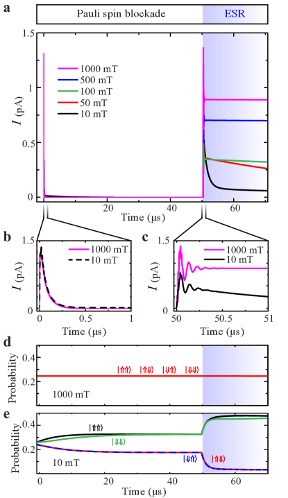
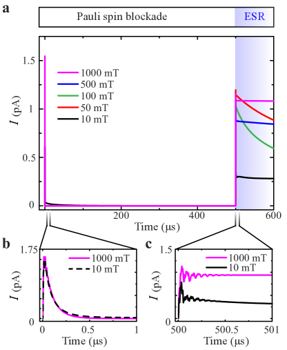
At high magnetic fields, mT, there is an initial peak in the current due to the tunneling of the electrons into the (1,1) charge region, see Fig. 3a. In a time s PSB is reached and the current is blocked (Fig. 3b). After application of the ESR excitation the current initially spikes and coherent oscillations can be seen corresponding to electron spin rotations introducing singlet content at a frequency determined by the ESR field strength ( MHz, Fig. 3c). The current quickly finds a steady state centred around the oscillations from the ESR driving. During this time, the nuclear spins are unaffected by the electron transport. Figure 3d shows the four nuclear spin state projections, .
At low magnetic fields, mT, the nuclear spin dynamics play a larger role in determining the current through the donors. Here the hyperfine interaction can cause electron-nuclear spin flip-flops () McCamey et al. (2009, 2010). This process is seen to increase the nuclear spin and populations to 0.3 whilst the system moves into PSB, see Fig. 3e. The flip-flop process is further amplified when ESR is applied during which the nuclear and populations approach zero. Consequently, this reduces the mixing between and since . Irrespective of the initial nuclear spin state, PSB cannot be lifted at low magnetic fields for double donor transport. We refer to this effect as “nuclear spin blockade” since the current through the donors is being blocked as a result of the nuclear spin states.
IV Nuclear spin readout
In the same way that PSB has been used to perform single electron spin readout in electron transport Koppens et al. (2006), we investigated if nuclear spin blockade can be used to perform readout of a single nuclear spin. Even at high magnetic fields nuclear spin blockade prevents current flow if the nuclear spin states are aligned ( or ) and allows current to flow if they are anti-aligned ( or ). Importantly, at high fields the nuclear spin states remain unaffected by the electron transport; therefore, it is possible to use nuclear spin blockade as a readout mechanism for the nuclear spin states.
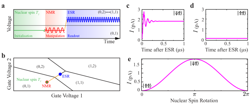
The spin measurement protocol consists of 3 stages: initialisation, manipulation and readout, see Fig. 4a,b. We initialise in the (0,1) charge region by waiting for the of the nuclear spins, thereby preparing them in the ground state, . The manipulation step involves applying NMR to the PL nuclear spin (which does not have an electron present) at a frequency . Importantly, this will not effect the PR nuclear spin due to the presence of the donor electron. The readout consists of moving to the (1,1)(0,2) transition and applying ESR to test the presence of nuclear spin blockade. If the nuclear spin on PL is then current will flow through the donors (Fig. 4c); however, if the nuclear spin is then the current will be blocked (Fig. 4d). The current is also linearly proportional to the orientation of the nuclear spin; that is, if the total nuclear spin state is then the current will be half that of the state, see Fig. 4e.
V Stark shift and donor clusters
In this final section we extend the simulation work to examine non-idealised scenarios of Stark shifted contact hyperfine interactions and donor clusters (multi-donor quantum dots) in donor based transport, for example, in Ref. Weber et al. (2012, 2014); Watson et al. (2014).
The electron wavefunction around a donor nuclei can be distorted by electric fields which changes the contact hyperfine interaction, known as the Stark effect Buch et al. (2013); Bradbury et al. (2006). Due to the stray electric fields in the silicon crystal, e.g. from electronic gates or charges, it is most likely that two donors will naturally experience different hyperfine interactions. This inherent Stark shift is typically a few MHz in frequency Pla et al. (2012) and will create a difference in the hyperfine interaction between the two donors, .
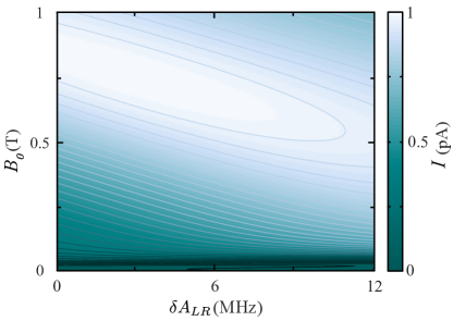
Figure 5 shows the steady state current after PSB and ESR (as in Fig. 3a) for various magnetic fields and values. The current increases with the magnetic field up to a certain field and interestingly there is an optimum for any given . At high magnetic fields the current decreases as becomes larger. This is due to decreasing when the spins are anti-aligned, resulting in less mixing and a lower current. At low magnetic fields the effect is reversed. Here, we are subject to nuclear spin blockade as previously discussed, however increasing will only increase resulting in a higher current.
Using scanning tunneling microscopy (STM) hydrogen lithography it has been shown that donor clusters consisting of a small number of P atoms can be fabricated in Si that exhibit PSB Weber et al. (2014). It is therefore possible to engineer a system consisting of a single donor and a two donor cluster in transport, essentially controlling the hyperfine interaction at the atomic scale. Now, in this system the electrons will always experience a across the two dots, ensuring there is substantial mixing () between the and states to lift PSB. This can be seen if we consider the 8 possible nuclear configurations: , , , , , , , , where the first term is the spin state for PL and the second term with a two nuclear spin state is for 2PR.
We simulate the current through a single donor (PL) and two donor cluster (2PR) in Fig. 6a at different magnetic fields with the initial state at . With this single and two donor cluster scenario, the nuclear spins take longer to reach a steady state configuration despite the electron spins reaching PSB in the same time scale as the single donor case, Fig. 6b. As a consequence we simulate the dynamics here for much longer.
During ESR excitation the current is seen to oscillate with a beating due to the different hyperfine interactions experienced by each electron, see Fig. 6c. For all magnetic field strengths, the current is higher than it was in the single donor cases. Importantly, even at low magnetic fields, and in contrast to the single donor dynamics (Fig. 3a), the current does not decay to zero. Instead, it finds a steady state solution centered around the coherent oscillations indicating that nuclear spin blockade is no longer present.
VI Summary
We have developed a numerical model to investigate electron spin transport through donors in silicon. Our findings show that there are surprising effects that arise due to the quantised nature of the donor nuclei. We show how it is possible to map out the electron exchange interaction using simple transport measurements and predict a new current blockade mechanism as a consequence of nuclear spin dynamics. This is in contrast to other systems such as GaAs double quantum dots where large fluctuating nuclear spin baths averages out the quantum nature of the nuclear spins and these effects are not observed.
Importantly, we find that for low magnetic fields, mT, where long electron times Morello et al. (2010) and faster ESR rotations are possible, nuclear spin blockade prevents the transfer of the electron spins across the donors. Therefore, electron spin readout can only be performed at high magnetic fields; in which, the nuclear spin states are initialised in or otherwise and there will be no mixing. In addition, we demonstrate that there is an optimum field for a given Stark shift across the donors to achieve the maximum current after ESR driving.
Interestingly, we show how nuclear spin blockade can be utilised as a new readout mechanism for nuclear spins. This method, which only requires electron transport measurements and removes the need for traditional charge sensors will be a useful experimental tool for probing multi-donor interactions. The nuclear spin coherence times can be measured during electron shuttling which is critical for many proposed spin transport protocols Cirac and Zoller (2000); Skinner et al. (2003).
Finally, we demonstrate that for electron spin transport experiments where nuclear spin blockade is undesirable, multi-donor clusters can be used since they allow for lifting of PSB even at low magnetic fields. Advances in fabrication technologies, in particular STM lithography, offers the ability to tailor hyperfine interactions at the atomic scale for absolute control over the combined electron-nuclear spin system.
Our results provide important insights into the complex spin dynamics in double donor systems. Such an understanding is necessary for two-qubit interactions Kalra et al. (2014) and spin transport protocols in multi-donor chains Oh et al. (2013) for scalable solid-state quantum computing architectures Hollenberg et al. (2006).
Acknowledgments
We thank T. L. Keevers and J. G. Keizer for helpful discussions. This research was conducted by the Australian Research Council Centre of Excellence for Quantum Computation and Communication Technology (project no. CE110001027) and the US National Security Agency and US Army Research Office (contract no. W911NF-08-1-0527). M.Y.S. acknowledges an ARC Laureate Fellowship.
Appendix A Hamiltonian definition
The Hamiltonian for exchange coupled donors including hyperfine, and electrical detuning, written in the singlet-triplet basis of the donor electrons is given by,
| (4) |
where in the Zeeman term, and the gyromagnetic ratios of the electron and nuclear spin states are GHz/T and MHz/T which will define the respective resonance conditions during either electron or nuclear spin excitation. Throughout the article we assume that the donors are in the weak coupling regime where valley-orbit effects are negligible.
The terms and are the electron spin operators for the (1,1) charge state and and are the nuclear spin operators for PL and PR (with donors numbers for single donors). To account for tunneling out of the state to the drain we have included the single electron states and which represent the spin states of the electron in the (0,1) charge state Koppens et al. (2007). For these single electron states, the system has three particles, two nuclei and one electron spin such that the hyperfine coupling is only between the electron spin, , and the second donor nuclei, . By considering the two donor nuclei quantum mechanically we can obtain the full system spin dynamics.
In total our Hamiltonian is spanned by where represents the nuclear subspace of states and the electron subspace consisting of , where .
To include incoherent terms we make use of a technique commonly used in the ESR/NMR community Jeener (1982); Ernst et al. (1987); Mayne (2007), which involves transforming from Hilbert space () to a higher dimensional space—Liouville space, . The incoherent processes can then be gathered into the dissipator superoperator, in that can model non-trace preserving decoherence processes without the need of finding the operators in .
Appendix B Rotating wave approximation
The ESR term in the Hamiltonian (Eq. 4) is
| (5) |
where we chose a realistic mT as the microwave magnetic field strength Koppens et al. (2006); Pla et al. (2012), its frequency and , , are the electron -spin operators for the (1,1) and (0,1) charge state respectively. To remove the time-dependence of the ESR field we can make a transformation from the laboratory frame to the rotating frame of the Larmor frequency () of the electron spins. This is simply a rotation about by an angle . We can then remove the faster rotating terms by making the rotating wave approximation. This transforms the Hamiltonian according to
| (6) |
This amounts to a two term addition to the Hamiltonian
| (7) |
where is the non-rotating Hamiltonian, and . contains the ESR driving terms and is the correction term due to the approximation ( and is the operator for the entire Hilbert space).
Appendix C Liouville Space
To incorporate decoherence and relaxation into the time evolution of the density operator, a master equation approach can be used. The problem is treated in a higher-dimensional space, known as Liouville space, . The master equation in Liouville space is given by Limes et al. (2013),
| (8) |
Importantly, the density operator is now a vector of length , which is operated upon by the Liouvillian superoperator, and the dissipator superoperator representing incoherent terms. When is time-independent Eq. 8 has the solution,
| (9) |
Appendix D The dissipator superoperator
The dissipator superoperator term contains the tunnel rates between the source and PL, the drain and PR, and respectively. The elements of that contain these rates are determined by the effect they have on the system Koppens et al. (2005, 2007).
Two electron transport cycles were studied in this paper, for the first case: (0,1)(0,2)(1,1)(0,1), the electrons are tunneling from the drain through the dots to the source. The diagonal dissipator elements in this scneario are,
| (10) | ||||
where indicates the the density operator element that acts upon. The off-diagonal elements between states and are
| (11) |
here () if or (, ); otherwise, it is zero. The tunneling rates account for the loss of coherence between the states and during transport and must be included to ensure positivity of the density operator.
The current through donors is given by the probability of the system to be in the (1,1) charge configuration multiplied by the tunnel rate from PL to the drain
| (12) |
For the electron transport cycle: (0,1)(1,1)(0,2)(0,1), the electrons are tunneling from the source through the donors to the drain. So here the dissipator elements are essentially reversed
| (13) | ||||
where now, for the off-diagonal elements, () if ( or ); otherwise, it is zero.
To determine the current through the donors we calculate the probability for the system to be in multiplied by the tunnel rate from PR to the drain Jouravlev and Nazarov (2006)
| (14) |
Throughout the paper we choose MHz, such that it is less than so that the hyperfine interaction has time to mix the electron states but still large enough to give an appreciable current through the donors.
References
- Johnson et al. (2005) A. C. Johnson, J. R. Petta, C. M. Marcus, M. P. Hanson, and A. C. Gossard. Singlet-triplet spin blockade and charge sensing in a few-electron double quantum dot. Nature, 435:925–928, 2005.
- Koppens et al. (2005) F. H. L. Koppens, J. A. Folk, J. M. Elzerman, R. Hanson, L. H. Williems van Beveran, I. T. Vink, H. P. Tranitz, W. Wegscheider, L. P. Kouwenhoven, and L. M. K. Vandersypen. Control and detection of singlet-triplet mixing in a random nuclear field. Science, 309:1346–1350, 2005.
- Koppens et al. (2006) F. H. L. Koppens, C. Buizert, K. J. Tielrooij, I. T. Vink, K. C. Nowack, T. Meunier, L. P. Kouwenhoven, and L. M. K. Vandersypen. Driven coherent oscillations of a single electron spin in a quantum dot. Nature, 442:766–771, 2006.
- Nowack et al. (2011) K. C. Nowack, M. Shafiei, M. Laforest, G. E. D. K. Prawiroatmodjo, L. R. Schreiber, C. Recihl, W. Wegscheider, and L. M. K. Vandersypen. Single-shot correlations and two-qubit gate of solid-state spins. Science, 333:1269–1272, 2011.
- Petta et al. (2005) J. R. Petta, A. C. Johnson, J. M. Taylor, E. A. Laird, A. Yacoby, M. D. Lukin, C. M. Marcus, M. P. Hanson, and A. C. Gossard. Coherent manipulation of coupled electron spins in semiconductor quantum dots. Science, 309:2180–2184, 2005.
- Schuetz et al. (2014) M. J. A. Schuetz, E. M. Kessler, L. M. K. Vandersypen, J. I. Cirac, and G. Giedke. Nuclear spin dynamics in double quantum dots: Multistability, dynamical polarisation, criticality, and entanglement. Phys. Rev. B, 89:195310, 2014.
- Prati et al. (2012) E. Prati, M. Hori, F. Guagliardo, G. Ferrari, and T. Shinada. Anderson-mott transition in arrays of a few dopant atoms in a silicon transistor. Nature Nanotech., 7:443–447, 2012.
- Gonzalez-Zalba et al. (2014) M. F. Gonzalez-Zalba, A. Saraiva, M. J. Calderon, D. Heiss, B. Koiller, and A. J. Fergurson. An exchange-coupled donor molecule in silicon. Nano Lett., 14:5672–5676, 2014.
- Fuechsle et al. (2012) M. Fuechsle, J. A. Miwa, S. Mahapatra, H. Ryu, S. Lee, O. Warschkow, L. C. L. Hollenberg, G. Klimeck, and M. Y. Simmons. A single-atom transistor. Nature Nanotech., 7:242–246, 2012.
- Weber et al. (2012) B. Weber, S. Mahapatra, T. F. Watson, and M. Y. Simmons. Engineering independent electrostatic control of atomic-scale (4 nm) silicon double quantum dots. Nano Lett., 12:4001–4006, 2012.
- Buch et al. (2013) H. Buch, S. Mahapatra, R. Rahman, A. Morello, and M. Y. Simmons. Spin readout and addressability of phosphorous-donor clusters in silicon. Nature Commun., 4:2017, 2013.
- Hollenberg et al. (2006) L. C. L. Hollenberg, A. D. Greentree, A. G. Fowler, and C. J. Wellard. Two-dimensional architectures for donor-based quantum computing. Phys. Rev. B, 74:045311, 2006.
- Bose (2003) S. Bose. Quantum communication through an unmodulated spin chain. Phys. Rev. Lett., 91:207901, 2003.
- Bose (2007) S. Bose. Quantum communication through spin chain dynamics: an introductory overview. Contemp. Phys., 48:13–30, 2007.
- Kay (2010) A. Kay. Perfect, efficient, state transfer and its applications as a constructive tool. Int. J. Quantum Inf., 8:641, 2010.
- Rahman et al. (2009) R. Rahman, S. H. Park, J. H. Cole, A. D. Greentree, R. P. Muller, G. Klimeck, and L. C. L. Hollenberg. Atomistic simulations of adiabatic coherent electron transport in triple donor systems. Phys. Rev. B, 80:035302, 2009.
- Rahman et al. (2010) R. Rahman, R. P. Muller, J. E. Levy, M. S. Carroll, G. Klimeck, A. D. Greentree, and L. C. L. Hollenberg. Coherent electron transport by adiabatic passage in an imperfect donor chain. Phys. Rev. B, 82:155315, 2010.
- Cirac and Zoller (2000) J. I. Cirac and P. Zoller. A scalable quantum computer with ions in an array of microtraps. Nature, 404:579–581, 2000.
- Skinner et al. (2003) A. J. Skinner, M. E. Davenport, and B. E. Kane. Hydrogenic spin quantum computing in silicon: A digital approach. Phys. Rev. Lett., 90:087901, 2003.
- Loss and DiVincenzo (1998) D. Loss and D. P. DiVincenzo. Quantum computation with quantum dots. Phys. Rev. A, 57:120–126, 1998.
- van der Wiel et al. (2003) W. G. van der Wiel, S. De Franceschi, J. M. Elzerman, T. Fujisawa, S. Tarucha, and L. P. Kouwenhoven. Electron transport through double quantum dots. Rev. Mod. Phys., 75:1–22, 2003.
- Taylor et al. (2007) J. M. Taylor, J. R. Petta, A. C. Johnson, A. Yacoby, C. M. Marcus, and M. D. Lukin. Relaxation, dephasing, and quantum control of electron spins in double quantum dots. Phys. Rev. B, 76:035315, 2007.
- Hanson et al. (2007) R. Hanson, L. P. Kouwenhoven, J. R. Petta, S. Tarucha, and L. M. K. Vandersypen. Spins in few-electron quantum dots. Rev. Mod. Phys., 79:1217–1265, 2007.
- Schliemann et al. (2003) J. Schliemann, A. Khaetskii, and D. Loss. Electron spin dynamics in quantum dots and related nanostructures due to hyperfine interaction with nuclei. J. Phys.: Condens. Matter, 15:R1809–R1833, 2003.
- Muhonen et al. (2014) J. T. Muhonen, J. P. Dehollain, A. Laucht, F. E. Hudson, R. Kalra, T. Sekiguchi, K. M. Itoh, D. N. Jamieson, J. C. McCallum, A. S. Dzurak, and A. Morello. Storing quantum information for 30 seconds in a nanoelectronic device. Nature Nanotech., 9:986–991, 2014.
- Koiller et al. (2002) B. Koiller, X. Hu, and S. Das Sarma. Exchange in silicon-based quantum computer architecture. Phys. Rev. Lett., 88:027903, 2002.
- Wellard et al. (2003) C. J. Wellard, L. C. L. Hollenberg, F. Pariosoli, L. M. Kettle, H.-S. Goan, J. A. L. McIntosh, and D. N. Jamieson. Electron exchange coupling for single-donor solid-state spin qubits. Phys. Rev. B, 68:195209, 2003.
- Ernst et al. (1987) R. R. Ernst, G. Bodenhausen, and A. Wokaun. Principles of Nuclear Magnetic Resonance in One and Two Dimensions. Oxford University Press, 1987.
- Nazarov (1993) Yu. V. Nazarov. Quantum interference, tunnel junctions and resonant tunneling interferometer. Physica B, 189:57–69, 1993.
- Jouravlev and Nazarov (2006) O. N. Jouravlev and Y. V. Nazarov. Electron transport in a double quantum dot governed by a nuclear magnetic field. Phys. Rev. Lett., 96:176804, 2006.
- Ono et al. (2002) K. Ono, D. G. Austing, Y. Tokura, and Y. Tarucha. Current rectification by Pauli exclusion in a weakly coupled double quantum dot system. Science, 297:1313–1317, 2002.
- Koppens et al. (2007) F. H. L. Koppens, C. Buizert, I. T. Vink, K. C. Nowack, T. Meunier, L. P. Kouwenhoven, and L. M. K. Vandersypen. Detection of single electron spin resonance in a double quantum dot. J. Appl. Phys., 101:081706, 2007.
- McCamey et al. (2009) D. R. McCamey, J. van Tol, G. W. Morely, and C. Boehme. Fast nuclear spin hyperpolarization of phosphorus in silicon. Phys. Rev. Lett., 102:027601, 2009.
- McCamey et al. (2010) D. R. McCamey, J. van Tol, G. W. Morely, and C. Boehme. Electronic spin storage in an electrically readable nuclear spin memory with a lifetime seconds. Science, 330:1652–1656, 2010.
- Weber et al. (2014) B. Weber, Y. H. Matthias Tan, S. Mahapatra, T. F. Watson, H. Ryu, R. Rahman, L. C. L. Hollenberg, G. Kilmeck, and M. Y. Simmons. Spin blockade and exchange in Coulomb-confined silicon double quantum dots. Nature Nanotech., 9:430–435, 2014.
- Watson et al. (2014) T. Watson, B. Weber, J. A. Miwa, S. Mahapatra, R. M. P. Heijen, and M. Y. Simmons. Transport in asymmetrically coupled donor-based silicon triple quantum dots. Nano Lett., 14:1830–1835, 2014.
- Bradbury et al. (2006) F. R. Bradbury, A. M. Tyryshkin, G. Sabouret, J. Bokor, T. Schenkel, and S. A. Lyon. Stark tuning of donor electron spins in silicon. Phys. Rev. Lett., 97:176404, 2006.
- Pla et al. (2012) J. J. Pla, K. Y. Tan, J. P. Dehollain, W. H. Lim, J. J. L. Morton, D. N. Jamieson, A. S. Dzurak, and A. Morello. A single-atom electron spin qubit in silicon. Nature, 489:541–545, 2012.
- Morello et al. (2010) A. Morello, J. J. Pla, F. A. Zwanenburg, K. W. Chan, K. Y Tan, H. Huebl, M. Mottonen, C. D. Nugroho, C. Yang, J. A. van Donkelaar, A. D. C. Alves, D. N. Jamieson, C. C. Escott, L. C. L. Hollenberg, R. G. Clark, and A. S. Dzurak. Single-shot readout of an electron spin in silicon. Nature, 467:687–691, 2010.
- Kalra et al. (2014) R. Kalra, A. Laucht, C. D. Hill, and A. Morello. Robust two-qubit gates for donors in silicon controlled by hyperfine interactions. Phys. Rev. X, 4:021044, 2014.
- Oh et al. (2013) S. Oh, Y.-P. Shim, J. Fei, M. Friessen, and X. Hu. Resonant adiabatic passage with three qubits. Phys. Rev. A, 87:022332, 2013.
- Jeener (1982) J. Jeener. Superoperators in magnetic resonance. Adv. Magn. Opt. Res., 10:1–51, 1982.
- Mayne (2007) C. L. Mayne. Liouville equation of motion. eMagRes., 2007.
- Limes et al. (2013) M. E. Limes, J. Wang, W. J. Baker, S.-Y. Lee, B. Saam, and C. Boehme. Numerical study of spin-dependent transition rates within pairs of dipolar and exchange coupled spins with during magnetic resonant excitation. Phys. Rev. B, 87:165204, 2013.