Crack Front Segmentation and Facet Coarsening in Mixed-Mode Fracture
Abstract
A planar crack generically segments into an array of “daughter cracks” shaped as tilted facets when loaded with both a tensile stress normal to the crack plane (mode I) and a shear stress parallel to the crack front (mode III). We investigate facet propagation and coarsening using in-situ microscopy observations of fracture surfaces at different stages of quasi-static mixed-mode crack propagation and phase-field simulations. The results demonstrate that the bifurcation from propagating planar to segmented crack front is strongly subcritical, reconciling previous theoretical predictions of linear stability analysis with experimental observations. They further show that facet coarsening is a self-similar process driven by a spatial period-doubling instability of facet arrays with a growth rate dependent on mode mixity. Those results have important implications for understanding the failure of a wide range of materials.
pacs:
62.20.Mk, 46.50.+a, 46.15. xCrack propagation is a main mode of materials failure. Understanding and controlling this complex phenomenon continues to pose both fundamental and practical challenges. While quasi-static planar crack growth with a tensile stress normal to the fracture plane (mode I) is well-understood, geometrically much more intricate crack patterns can form in varied conditions Bouchbinder et al. (2010). A few examples include thermal or drying stresses that can cause cracks to oscillate and branch Yuse and Sano (1993); Ronsin et al. (1995), or re-organize into complex three-dimensional patterns Gauthier et al. (2010); Maurini et al. (2013); Bourdin et al. (2014), nonlinear elastic effects that can induce crack front instabilities even in mode I Baumberger et al. (2008), or the superposition of mode I and a shear stress parallel to the crack front (mode III). This mixed-mode I+III fracture is observed in a wide range of engineering and geological materials to produce arrays of daughter cracks, which are shaped as tilted facets and form by a geometrically complex crack front segmentation process Sommer (1969); Knauss (1970); Palaniswamy and Knauss (1975); Hourlier and Pineau (1979); Pollard et al. (1982); Suresh and Tschegg (1987); Pollard and Aydin (1988); Yates and Miller (1989); Cooke and Pollard (1996); Lazarus (1997); Lazarus et al. (2001, 2008); Lin et al. (2010); Goldstein and Osipenko (2012); Pham and Ravi-Chandar (2014); Ronsin et al. (2014).
Recent theoretical progress has been made to characterize the crack-front instability leading to segmentation Pons and Karma (2010); Leblond et al. (2011) and to describe the propagation of daughter-crack arrays Leblond et al. (2015). However, theory and experiments have not produced a consistent picture. Griffith’s energetic criterion Griffith (1921) predicts that planar crack growth is possible when the elastic energy release rate
| (1) |
exceeds a critical material-dependent threshold , where and are the mode I and mode III stress intensity factors (SIF), respectively, which characterize stress divergences near the crack front, is the shear modulus and is Poisson’s ratio. Phase-field simulations of brittle mixed-mode I+III fracture have revealed that planar growth is linearly unstable against helical deformations of the crack front, which couple in-plane and out-of-plane perturbations and develop nonlinearly into facets Pons and Karma (2010). A subsequent linear stability analysis in the framework of linear elastic fracture mechanics (LEFM) Leblond et al. (2011) has predicted that this helical instability should occur when exceeds a threshold
| (2) |
which only depends on Poisson’s ratio. However, crack front segmentation is experimentally observed for values much smaller than this threshold Sommer (1969); Ronsin et al. (2014), or even vanishingly small Pham and Ravi-Chandar (2014). This apparent disagreement between linear stability analysis and experiment raises the question of whether LEFM and phase-field modeling are adequate theories to describe crack propagation in mixed-mode I+III brittle fracture. Also poorly understood is “facet coarsening”, the progressive increase of facet width and spacing with propagation length from the parent crack. Phase-field modeling Pons and Karma (2010) and experiments Cambonie and Lazarus (2014) suggest that coarsening may be a self-similar process, but its precise mechanism and dependence on mode mixity are not well understood.
In this letter, we investigate both facet propagation and coarsening by mixed-mode I+III fracture experiments that allow us to visualize in-situ complex crack morphologies during quasi-static propagation, thereby providing much more detailed geometrical information on crack front evolution than conventional post-mortem fractography. Moreover, we carry out phase-field simulations of those experiments that allow us to relate experimental observations to LEFM theory. The results help resolve the puzzling discrepancy between linear stability analysis and experiments with regards to facet formation and shed new light on the coarsening process.
Experiments are carried out using plexiglas beams and a traditional three or four point bending setup Sup . To introduce some amount of mode III, the initial planar notch in the sample is tilted at an angle from the mode I central plane of symmetry Buchholz et al. (2004); Lazarus et al. (2008). A special procedure is used to initiate a sharp crack with a straight front Sup . The corresponding values of the SIF for each angle and hence have been obtained by finite element calculations, which show that varies between approximately 0.1 and 0.5 when the notch angle varies between and , where zero angle corresponds to pure mode I loading. This range was selected because it contains the linear instability threshold predicted by Eq. (2) for Poisson’s ratio of plexiglass . Finite element calculations also show Lazarus et al. (2008) that is reasonably constant away from sample edges, thereby allowing us to investigate crack propagation at constant along a wide section of the parent crack inside the sample. Several beams were broken by fatigue in the bending set-up Sup . The advantage of this cyclic type of loading is that the crack advance (i) is quasi-static, while leaving the crack path unchanged in comparison to the one obtained under monotonical increasing loading Linning (1993) and (ii) controlled by the number of cycles so that complex crack morphologies can be observed in-situ at different stages of crack growth. Observations were made using a Leica binocular or a Keyence numerical microscope by transparency.
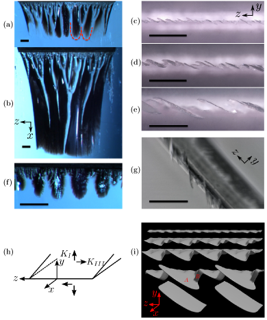
Examples of experimental images are shown in Fig. 1(a)-(g) for values of 0.3 and 0.5 corresponding to initial notch angles of and , respectively. Those images reveal several important features. Firstly, facets have a finger-shape with curved tips and flat sides that is consistent with the shape predicted by phase-field simulations (Fig. 1(i) and Movie 1 of Sup ). Secondly, facets form for values of both below and above the linear stability threshold . Within optical resolution, only energetically favored type A facets are observed to emerge from the parent crack with a well-defined tilt angle from the original fracture plane. Thirdly, facets coarsen by elimination of other facets leading to an increase of both facet width and facet spacing along the array with increasing propagation length. Coarsening is clearly visible from top views in Fig. 1(b) and in the sequence Fig. 1(c)-(e), which moreover shows that surviving facets maintain the same angle while overgrowing others. Additional views are given in Sup .
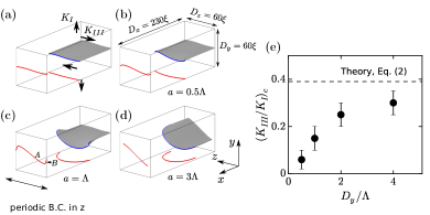
Simulations were carried out using a phase-field model of brittle fracture that, like gradient damage models Bourdin et al. (2000, 2014), regularizes stress-field divergences on a process zone scale around the crack front. All energy dissipation takes place on a characteristic timescale Karma et al. (2001). As shown by an asymptotic analysis of the phase-field model in the limit where is much smaller than all other dimensions Hakim and Karma (2009), fracture in this model is governed by standard crack propagation laws assumed in the LEFM theoretical framework, namely Griffith’s criterion and vanishing mode II SIF Goldstein and Salganik (1974). Since we are primarily interested in modeling crack evolution in a region away from the experimental sample boundaries where is approximately uniform Lazarus et al. (2008); Cambonie and Lazarus (2014), we carried out simulations in a rectangular slab geometry of length , width and height , defined in Fig. 2(b), with the origin defined at the center of the slab. We impose fixed displacements at , (mode I) and (mode III), periodic boundary conditions in that allow us to model a periodic array of daughter cracks infinite in Pons and Karma (2010). We use a “treadmill” that adds a strained layer at and removes a layer at when the crack has advanced by one lattice spacing. This allows us to simulate crack propagation lengths much longer than (), thereby modeling propagation in a slab infinitely long in Sup . We also choose to eliminate the influence of the two end-boundaries of the slab () on the central region of the slab () where the average crack front position is maintained by the treadmill. Standard expressions of linear elasticity are used to relate and to the SIF Sup and therefore to and where (twice the surface energy) is known in the phase-field model Karma et al. (2001); Hakim and Karma (2009). All simulations are performed with of plexiglass. We simulated both quasi-static propagation, where the elastic field is relaxed at each time step of crack advance, and dynamic propagation by solving the full elastodynamic equations. Both sets of simulations yielded similar results for the range where the ratio of the crack propagation speed to the shear wave speed is small enough to neglect inertial effects Sup .
We first carried out simulations to check quantitatively the theoretical prediction of Eq. (2). For this purpose, we slightly perturbed the planar parent crack with a small amplitude helical perturbation of the form , where and indicate the and components of deviations of the front from the reference planar crack, respectively, and fits one wavelength of the perturbation in the periodic domain in . The stability of planar crack propagation is then determined by tracking the amplitude of the perturbation that grows or decays exponentially in time Sup if propagation is unstable, as illustrated in Fig. 2(a)-(d), or stable, respectively. Simulations were carried out by increasing in small steps to determine the threshold , and repeating this procedure for increasing values of to quantify finite size effects. Fig. 2(e) shows that increases monotonously with and approaches a value reasonably close to the prediction of Eq. (2) in the large system size () limit. Consistent with the result of Fig. 2(e), an examination of strain fields shows that finite size effects becomes negligible when Sup . We conclude that LEFM theory (Eq. (2)) and phase-field modeling predict similar linear instability thresholds in the large system size limit, and that facets are experimentally observed well below this threshold.
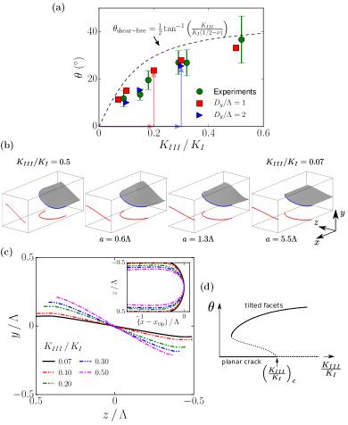
Next, in order to explore the nonlinear character of the bifurcation from planar to segmented crack front, we measured experimentally the facet tilt angle extracted from three-dimensional maps of post-mortem fracture surfaces obtained using a profilometer as detailed in Cambonie and Lazarus (2014). The angle is plotted versus in Fig. 3(a). Furthermore, we investigated computationally the propagation of periodic arrays of A facets, where coarsening is suppressed by choosing due to the periodic boundary conditions along . In this geometry, we tracked the steady-state branch of propagating solutions by decreasing starting from values above the linear instability threshold to values below this threshold, as low as 0.07 to span the entire experimental range of mode mixity. For each value, we allowed the facet to relax to a new stationary shape and tilt angle, as illustrated in Fig. 3(b) for a simulation where was decreased from 0.5 to 0.07. The computed tilt angles are compared to experimental results in Fig. 3(a) with the corresponding facet shapes shown in Fig. 3(c). Both the facet shapes, which gently curve at their extremities in the plane due to elastic interactions between neighboring facets, and the tilt angles are in good quantitative agreement with experimental observations within measurement errors. Fig. 3(a) also shows that computed tilt angles are weakly dependent on system size () and fall below the prediction of a simple theory, which assumes that facets are shear-free Pons and Karma (2010); Cooke and Pollard (1996). Those results demonstrate that propagating segmented front solutions exist over the entire range of investigated experimentally, including values less than . We conclude that the bifurcation from planar to segmented front is strongly subcritical, with bistability of planar and segmented crack growth for as illustrated schematically in Fig. 3(d).
To characterize coarsening in phase-field simulations, we investigated the stability of periodic array of facets by repeating the above series of simulations with two facets (). This geometry is motivated by the striking similarity between the coarsening behavior of facets in the present experiments (Fig. 1(a)-(g)) and coarsening of curved fronts in other interfacial pattern forming systems, in particular viscous fingering Kessler and Levine (1986) and dendritic crystal growth Warren and Langer (1993); Losert et al. (1996). In those systems, it is well-established that coarsening of finger arrays is associated with a spatial period-doubling linear instability of the array leading to elimination of one of every two fingers in the array by exponential amplification of small perturbations. Results of simulations illustrated in Fig. 4(a) show that arrays of facets exhibit a similar spatial period doubling instability driven by elastic interactions between facets. This instability yields an increase (decrease) of the SIF and hence the energy release rate at the tips of leading (lagging) facets. The amplification rate of instability is obtained by computing the difference of -tip position between leading and lagging facets, which grows exponentially in time starting from an infinitesimal perturbation, , where and are the initial facet growth velocity and spacing, respectively. The slopes of semi-log plots of versus in Fig. 4(b) yield values of that increase markedly with , showing that a larger mode III component leads to a faster elimination rate of facets.
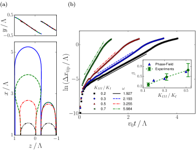
Coarsening, clearly visible in Fig. 1(b) and other experimental views Sup , was quantified experimentally by analyzing post-mortem fracture surfaces Cambonie and Lazarus (2014). The results show that the relation between the mean facet spacing and the crack propagation length is approximately linear, with a mean slope increasing with (inset of Fig. 4(b)). To relate the coarsening rates in phase-field simulations and experiments, we derive a simple evolution equation for the average array spacing based on dynamical mean-field picture as previously done for dendritic arrays Warren and Langer (1993). The coarsening rate where is the change of array spacing due to elimination of one of every two facets along the array or , while is the distance that the facets propagated during the elimination process. Since elimination occurs via exponential amplification of small perturbations, facets will propagate an average distance during this process, yielding the prediction , or where is a constant prefactor of order unity. The comparison in the inset of Fig. 4(b) shows that this simple theory is able to predict reasonably well the increase of the coarsening rate with up to the value of the constant prefactor determined from a global best fit to the experimental data for all values.
The present results reconcile the prediction of linear stability analysis (Eq. (2)) with experimental observations by showing that the bifurcation from planar to segmented crack growth is strongly subcritical; facet arrays exist as fundamental crack propagating solutions of LEFM for a range of values extending below the instability threshold. They further show that coarsening is driven by a spatial period doubling instability of facet arrays with a growth rate that depends on mode mixity. The reasonably good quantitative agreement between simulated and observed morphologies suggests that LEFM is an adequate theory to describe complex geometrical features of both brittle and fatigue cracks in mixed mode I+III fracture. While the present results show that the subcritical propagation of segmented cracks is theoretically possible, they do not identify the mechanism and scale of subcritical facet formation. As suggested by a recent LEFM analysis, materials imperfections may contribute to this process Leblond and Lazarus (2015). However, this scenario, and even more fundamentally the ability of LEFM to model subcritical facet formation, remain to be explored both computationally and experimentally.
Acknowledgements.
The research at Northeastern University was supported by Grant No. DE-FG02-07ER46400 from the U.S. Department of Energy, Office of Basic Energy Sciences and a seed grant from the Massachusetts Green High Performance Computing Center. The research at University Paris Sud benefited of financial support from ANR GeoSMEC (2012-BS06-0016-03). The authors thanks L. Auffray, D. Bonamy, F. Buchholz, V. Doquet, J.-C. Eytard, R. Pidoux, A. Tanguy for their help in the experiments and J.-B. Leblond for helpful discussions.References
- Bouchbinder et al. (2010) E. Bouchbinder, J. Fineberg, and M. Marder, Annu. Rev. Condens. Matter Phys. 1, 371 (2010).
- Yuse and Sano (1993) A. Yuse and M. Sano, Nature 362, 329 (1993).
- Ronsin et al. (1995) O. Ronsin, F. Heslot, and B. Perrin, Phys. Rev. Lett. 75, 2352 (1995).
- Gauthier et al. (2010) G. Gauthier, V. Lazarus, and L. Pauchard, EPL 89, 26002 (2010).
- Maurini et al. (2013) C. Maurini, B. Bourdin, G. Gauthier, and V. Lazarus, Int. J. Fract. 184, 75 (2013).
- Bourdin et al. (2014) B. Bourdin, J.-J. Marigo, C. Maurini, and P. Sicsic, Phys. Rev. Lett. 112, 014301 (2014).
- Baumberger et al. (2008) T. Baumberger, C. Caroli, D. Martina, and O. Ronsin, Phys. Rev. Lett. 100, 178303 (2008).
- Sommer (1969) E. Sommer, Eng. Fract. Mech. 1, 539 (1969).
- Knauss (1970) W. G. Knauss, Int. J. Fract. 6, 183 (1970).
- Palaniswamy and Knauss (1975) K. Palaniswamy and W. G. Knauss, in Mechanics Today, edited by Nemat-Nasser (Pergamon Press, 1975), vol. 4, pp. 87–148.
- Hourlier and Pineau (1979) F. Hourlier and A. Pineau, Mémoires Scientifiques de la Revue de Métallurgie 76, 175 (1979).
- Pollard et al. (1982) D. D. Pollard, P. Segall, and P. T. Delaney, Geol. Soc. Amer. Bull. 93, 1291 (1982).
- Suresh and Tschegg (1987) S. Suresh and E. K. Tschegg, J. Amer. Ceramic Soc. 70, 726 (1987).
- Pollard and Aydin (1988) D. D. Pollard and A. Aydin, Geol. Soc. Amer. Bull. 100, 1181 (1988).
- Yates and Miller (1989) J. R. Yates and K. J. Miller, Fatigue Fract. Eng. M. 12, 259 (1989).
- Cooke and Pollard (1996) M. L. Cooke and D. D. Pollard, J. Geophys. Res. 101, 3387 (1996).
- Lazarus (1997) V. Lazarus, Ph.D. thesis, Université Pierre et Marie Curie (Paris VI), France (1997).
- Lazarus et al. (2001) V. Lazarus, J. B. Leblond, and S. E. Mouchrif, J. Mech. Phys. Solids 49, 1421 (2001).
- Lazarus et al. (2008) V. Lazarus, F. G. Buchholz, M. Fulland, and J. Wiebesiek, Int. J. Fract. 153, 141 (2008).
- Lin et al. (2010) B. Lin, M. E. Mear, and K. Ravi-Chandar, Int. J. Fract. 165, 175 (2010).
- Goldstein and Osipenko (2012) R. V. Goldstein and N. M. Osipenko, Doklady Physics 57, 281 (2012).
- Pham and Ravi-Chandar (2014) K. H. Pham and K. Ravi-Chandar, Int. J. Fract. 189, 121 (2014).
- Ronsin et al. (2014) O. Ronsin, C. Caroli, and T. Baumberger, Europhys. Lett. 105, 34001 (2014).
- Pons and Karma (2010) A. J. Pons and A. Karma, Nature 464, 85 (2010).
- Leblond et al. (2011) J. B. Leblond, A. Karma, and V. Lazarus, J. Mech. Phys. Solids 59, 1872 (2011).
- Leblond et al. (2015) J. B. Leblond, V. Lazarus, and A. Karma, Int. J. Frac. 191, 167 (2015).
- Griffith (1921) A. A. Griffith, Phil. Trans. Roy. Soc. London, Series A 221, 163 (1921).
- Cambonie and Lazarus (2014) T. Cambonie and V. Lazarus, Procedia Materials Science 3, 1816 (2014).
- (29) See Supplemental Material at [URL will be inserted by publisher] for details of the experiments and phase-field simulations and movies.
- Buchholz et al. (2004) F.-G. Buchholz, A. Chergui, and H. A. Richard, Eng. Fract. Mech. 71, 455 (2004).
- Linning (1993) W. Linning, in Mixed-Mode Fatigue and Fracture (ESIS 14), edited by H. P. Rossmanith and K. J. Miller (Professional Engineering Publishing Ltd, 1993), pp. 201–215.
- Bourdin et al. (2000) B. Bourdin, G. A. Francfort, and J. J. Marigo, J. Mech. Phys. Solids 48, 797 (2000).
- Karma et al. (2001) A. Karma, D. A. Kessler, and H. Levine, Phys. Rev. Lett. 87, 045501 (2001).
- Hakim and Karma (2009) V. Hakim and A. Karma, J. Mech. Phys. Solids 57, 342 (2009).
- Goldstein and Salganik (1974) R. V. Goldstein and R. L. Salganik, Int. J. Fract. 10, 507 (1974).
- Kessler and Levine (1986) D. A. Kessler and H. Levine, Phys. Rev. A 33, 3625 (1986).
- Warren and Langer (1993) J. A. Warren and J. S. Langer, Phys. Rev. E 47, 2702 (1993).
- Losert et al. (1996) W. Losert, B. Q. Shi, H. Z. Cummins, and J. A. Warren, Phys. Rev. Lett. 77, 889 (1996).
- Leblond and Lazarus (2015) J. B. Leblond and V. Lazarus, J. Mech. Materials Structures 10, 299 (2015).