Nonlinear parity-time-symmetric transition in finite-size optical couplers
Abstract
Parity-time-symmetric (-symmetric) optical waveguide couplers offer a great potential for future applications in integrated optics. Studies of nonlinear -symmetric couplers present new possibilities for ultracompact configurable all-optical signal processing. Here, we predict nonlinearly triggered transition from a full to a broken -symmetric regime in finite-size systems described by smooth permittivity profiles and, in particular, in a conventional discrete waveguide directional coupler configuration with a rectangular permittivity profile. These results suggest a practical route for experimental realization of such systems.
One of the fundamental assumptions of quantum mechanics states that operators corresponding to physical observables possess a real spectrum of eigenvalues Shankar (1994). The most common class of operators having purely real eigenvalues are Hermitian operators. However, in 1998 Bender et al. Bender and Bottcher (1998); Bender et al. (2002) showed that a more general class of non-Hermitian parity-time-symmetric (-symmetric) operators also possesses a real spectrum. Consequently, Hamiltonians with complex potentials that fulfill the condition have real eigenvalues and describe physical phenomena. While the realization of such complex potentials in quantum mechanics is challenging, it is much easier to control them in optics. Indeed, the light propagation can be described by an optical analogue of the Schrödinger equation, where the complex dielectric permittivity distribution plays the role of potential and the imaginary part of the permittivity corresponds to gain or loss El-Ganainy et al. (2007); Klaiman et al. (2008).
The optical symmetry was experimentally demonstrated in linear optical waveguide couplers Rüter et al. (2010), which are important components for future fast, ultracompact, and configurable all-optical signal processing. Optical couplers with gain and loss were also studied in the nonlinear regime Chen et al. (1992), where unidirectionality Ramezani et al. (2010) and suppression of time reversal Sukhorukov et al. (2010) were shown. Phenomena related to the nonlinear symmetry were also studied in periodic systems, including solitons Musslimani et al. (2008); Suchkov et al. (2011); Abdullaev et al. (2011); Alexeeva et al. (2012); Miri et al. (2012); Wang and Aceves (2013), breathers Barashenkov et al. (2012) and their stability Nixon et al. (2012); Zezyulin and Konotop (2012).
Optical -symmetric systems, where , undergo a transition with the change of the ratio between the imaginary and the real part of the permittivity modulation depth (). Below a certain threshold value of this ratio, the system is in the full -symmetric regime and has purely real eigenvalues Guo et al. (2009); Rüter et al. (2010). For the ratio above this threshold value, the system is in the broken -symmetric regime. In this regime, a pair of modes possesses effective indices that are a pair of complex conjugate numbers, such that one mode experiences gain and the other loss. In linear systems, the transition from the full to the broken -symmetric regime (hereafter simply transition) is usually controlled by changing the amount of gain and loss in the system (varying ). Nevertheless, the ratio is also influenced by the amplitude of , which in nonlinear systems can be controlled by varying the incident light intensity. Recently, it has been shown that the nonlinearity can trigger a transition in an infinite periodic array of -symmetric waveguides described by cosine-like permittivity distribution Lumer et al. (2013).
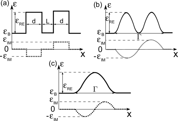
In this paper, we show that the nonlinear transition can be observed in ultracompact nonlinear couplers consisting of one or two -symmetric waveguides, which can be readily integrated on a chip. Figure 1 shows the three geometries under investigation: -symmetric couplers built of rectangular (a) and sinusoidal (b) waveguides; and a dimer (c), where both gain and loss are located in one waveguiding structure.
To study the nonlinear light propagation in one-dimensional (1D) -symmetric structures with Kerr-type nonlinearity, we use the scalar wave equation for the electric field :
| (1) |
where the operator denotes the 2D Laplacian operator, is the free-space wavevector, and is the free-space wavelength of light. The light propagates along the -direction, and both the structure and the field distributions are assumed to be invariant along the -direction. The linear relative complex permittivity distribution along the -coordinate is described by , where denotes the background relative permittivity and describes the linear complex permittivity modulation depth. The Kerr nonlinearity strength is quantified by , where denotes the vacuum permittivity, denotes the speed of light, and is nonlinear parameter corresponding to cubic nonlinearity used in the definition of the intensity dependent refractive index Boyd (2007). The light intensity is related to the electric field in the following way: , where . The nonlinearity in the structures studied here is nonzero only inside of the waveguides [i.e., if , then ].
Using the slowly varying envelope approximation , eq. 1 is transformed into the D nonlinear Schrödinger equation
| (2) |
Equation 2 is solved using the split-step Fourier method Feit and Fleck, Jr. (1978); Lax et al. (1981) in order to analyze the nonlinear dynamics of the light propagation in our -symmetric structures.
While some of the previous theoretical studies focused on the nonlinear light propagation in an infinite periodic cosine-like -symmetric waveguide array Lumer et al. (2013), here we show that the rich variety of nonlinear phenomena can be obtained in simpler finite-size systems of waveguides that are more feasible from the laboratory viewpoint. First, we study a nonlinear coupler built of two rectangular waveguides presented in fig. 1(a) and look for the nonlinear transition from the full to the broken -symmetric regime. The structure with the following parameters is studied: m, m, , and at the wavelength m.
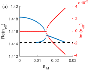
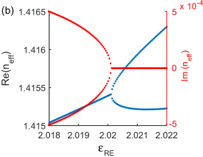
In order to study the properties of light in our -symmetric structures, we solve eq. 1 using two different methods. First, we study modal properties of the system in the linear regime []. We look for the field profiles that propagate with an effective index without changing their shape in the form . This allows us to transform eq. 1 into an eigenvalue problem for the modes of the waveguide described by and find the corresponding dispersion relations. We use these dispersion diagrams [shown in Figs. 2(a), (b)] to locate the symmetry breaking threshold, where two modes with purely real effective indices are transformed into a pair of modes with complex conjugate effective indices.
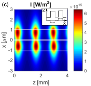
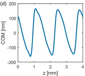
For the coupler parameters given above, this transition occurs at . Here, we study the system slightly above the phase transition (at , which corresponds to the broken -symmetric regime for low light intensity). The nonlinear dynamics shown in Figs. 2(c), (d) proves that it is possible to observe the nonlinearly triggered transition in the dimer built of two rectangular waveguides [(shown in fig. 1(a)]. In this and all of the other configurations studied here, we excite the gain mode that initially increases its energy. At the beginning of the propagation, the light intensity is low and the system is located in the broken -symmetric regime. The light is mostly located in the gain waveguide, as it can be seen in fig. 2(d) showing the -coordinate of the center of mass (COM) calculated as . With the increase of the light intensity, the real part of the permittivity of the waveguides also increases. Since the transition depends on the ratio between the real and imaginary parts of permittivities Lumer et al. (2013), the increase of drives the system back to the full -symmetric regime [the dispersion relation presented in Fig. 2(b) shows that with the increase of , the system is transformed from the broken to the full -symmetric regime]. After the transition occurs, the light intensity in the gain waveguide reaches its maximum, and then it starts to diminish. At the same time, energy is coupled to the lossy waveguide in which the maximum intensity is reached slightly later and then also starts to decay. With the decrease of the total intensity in the coupler, accompanied by the decrease of the nonlinear permittivity modulation depth, the system is transformed back to the broken -symmetric regime. This cycle repeats itself during the propagation.
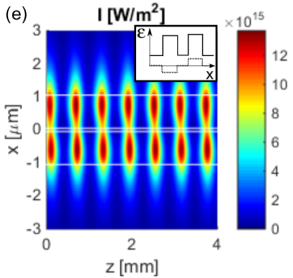
Figure 2(e) presents the light evolution in the same system as the one in Figs. 2(a), (b) but for a higher excitation power density . We can observe that with the increase of the initial power, the period of oscillations decreases and the maximum light intensity increases. At the low power level, the oscillation period is approximately equal to mm, and the peak power corresponds to the nonlinear permittivity modulation depth of the order of . For high power, the period decreases to mm, and the maximum nonlinear permittivity modulation depth increases to .
Let us now compare these results for the discrete rectangular waveguide-based coupler with those for the coupler with a smooth cosine-like profile described by
| (3) |
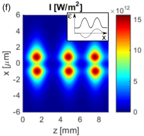
and shown in fig. 1(b). Here, , denotes the full width of the dimer, and both and are real quantities. While such smooth cosine-like profiles are often used in theoretical studies of periodic structures and waveguides, it maybe challenging to realize such profiles in laboratory experiments. The cosine-like coupler parameters are: , , and m. The imaginary part of the permittivity is chosen to be , which is just above the transition point located at . It is noteworthy, that the dynamics of nonlinear wave propagation in such a structure, shown in fig. 2(f), resembles that of the discrete waveguides based coupler [see fig. 2(e)], suggesting that the nonlinearity-induced transition is not sensitive to the exact refractive index profile of the structure. These results are likely to be important for the experimental observation of the predicted phenomena.
Now, having established the similarity between light propagation in -symmetric structures defined by rectangular and smooth permittivity profiles, we consider the effect of different distributions of both the real and imaginary parts of the dielectric permittivity on the transition dynamics. In particular, we investigate a finite-size -symmetric dimer that can be described by
| (4) |
with Kerr-type nonlinearity. The geometry of a single dimer described by eq. 4 is shown in fig. 1(c), and the parameters are , , and m. Here, the transition from the full to the broken -symmetric regime is also observed. The threshold in the linear case is located at .
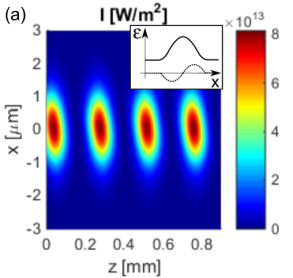
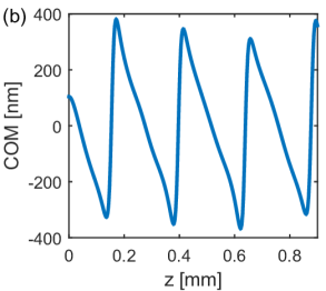
The nonlinear propagation of light in a single dimer is presented in Figs. 3(a), (b). It resembles the propagation of light in the unit cell of a periodic array of dimers presented in Figs. 3(d), (f) in Ref. Lumer et al. (2013). However, in Ref. Lumer et al. (2013) the parameters of the array were chosen in such a way that the energy transfer from the gain region to the lossy one was visible only from the plot showing the center of mass and not from the color map presenting the intensity evolution during the propagation. On the contrary, for the parameters chosen here, this energy transfer, illustrated as the displacement of the center of mass in fig. 3(b), is also clearly visible from the intensity distribution presented in fig. 3(a). Indeed, the intensity distribution pattern that changes periodically along the -coordinate is visibly tilted away from the vertical axis, indicating the energy transfer from the top part of the dimer (gain region) to the bottom part (loss region).
Figures 3(a), (b) show that the system is initially (for low light intensity) in the broken -symmetric regime. The gain mode of the system is excited, and the energy of this mode increases. Similar to the case shown in fig. 2, this increase is accompanied by the increase of the real part of the permittivity due to the Kerr effect. When the permittivity modulation depth is sufficiently high, it brings the system back to the full -symmetric regime. Initially, the energy is stored in the gain mode of the broken -symmetric system. In the full -symmetric regime, this mode is no longer an eigenmode of the system, and the distribution of light (still experiencing gain as it is localized mostly in the gain region) is attracted to the center of the dimer, where the permittivity is the highest Lumer et al. (2013). Therefore, the beam possesses a nonzero transverse momentum directed towards negative -direction. Due to this momentum, the beam crosses the center of the dimer and as a result is mostly localized in the region with loss. Consequently, the total energy rapidly decreases and the system is transformed back to the broken -symmetric regime. In this regime, the part of the energy stored in the loss mode vanishes quickly and the part stored in the gain mode starts to grow again. This cycle repeats, as it is seen in Figs. 3(a), (b).
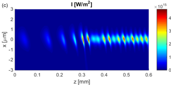
It is noteworthy that in the case of a single dimer, for which the parameters are chosen in such a way, that the system is higher above the transition ( while it was in the example discussed above), the nonlinear transition also occurs, but it has a different character. The propagation of light in such a system is presented in fig. 3(c). We see that in the initial phase of the propagation (up to 0.3 mm), the oscillations are aperiodic, and the period of oscillations decreases. With the decrease of the oscillation period, the energy is transferred from the gain part of the dimer to the lossy part within a shorter distance. At the beginning of the propagation, the transverse component (toward negative values) of the beam momentum is low enough so that the beam stays confined in the dimer. During the propagation, this momentum increases and at the propagation distance mm, it causes a significant quantity of energy to be outcoupled from the dimer and to propagate toward negative values of . After this point, the propagation pattern becomes more regular: the period of oscillations is kept constant, and only the peak intensity reached during the oscillations changes (the variations of the peak intensity are at the level of 50%). The irregularity of the propagation in the system located higher above the transition can be explained by the fact that the light intensity here is 20 times larger than that for the system closer to the transition. At the same time, the period of the oscillations is about 4 times smaller, and consequently, the changes in the light intensity are much more abrupt than in the system closer to the transition. These rapid changes cause more irregular behavior of the system high above the transition.
Here, we briefly compare the field distribution in a pair of waveguides shown in fig. 2 and the single cosine-like dimer shown in fig. 3. The main difference lies in the fact that in the case of the single cosine-like dimer, the field possesses a single intensity maximum whose location is described by the center of mass that shifts from the gain to the loss part of the waveguide, whereas in the pair of waveguides the field distribution has two maxima—one in each waveguide. In the system of two waveguides, it is the ratio between these maximum intensities (or more precisely the integrated power in each of the waveguides) that determines whether gain or loss dominates at a given propagation distance.
In conclusions, we have studied nonlinear dynamics of light propagating in finite-size parity-time-symmetric optical couplers. We have shown that the nonlinearly triggered transition from the full to the broken -symmetric regime can be observed for various finite-size couplers built of two rectangular and cosine-like waveguides. We have shown that the nonlinearly triggered transition between the full and the broken -symmetric regime also occurs in a single -symmetric cosine-like dimer. Moreover, we have found that the light propagation in smooth and discrete waveguide couplers is qualitatively similar. These results suggest a practical and simple route to experimental verification and applications of this kind of nonlinear transition.
Acknowledgements
We thank Dr. Liang Feng from University at Buffalo, The State University of New York for helpful discussions. This work was supported by US ARO Award #W911NF-15-1-0152.
References
- Shankar (1994) R. Shankar, Principles of Quantum Mechanics, ed. (Plenum Press, New York, 1994).
- Bender and Bottcher (1998) C. M. Bender and S. Bottcher, Phys. Rev. Lett. 80, 5243 (1998).
- Bender et al. (2002) C. M. Bender, D. C. Brody, and H. F. Jones, Phys. Rev. Lett. 89, 270401 (2002).
- El-Ganainy et al. (2007) R. El-Ganainy, K. G. Makris, D. N. Christodoulides, and Z. H. Musslimani, Opt. Lett. 32, 2632 (2007).
- Klaiman et al. (2008) S. Klaiman, U. Günther, and N. Moiseyev, Phys. Rev. Lett. 101, 080402 (2008).
- Rüter et al. (2010) C. E. Rüter, K. G. Makris, R. El-Ganainy, D. N. Christodoulides, M. Segev, and D. Kip, Nature Phys. 6, 192 (2010).
- Chen et al. (1992) Y. Chen, A. W. Snyder, and D. N. Payne, IEEE Journ. Quant. Electron. 28, 239 (1992).
- Ramezani et al. (2010) H. Ramezani, T. Kottos, R. El-Ganainy, and D. N. Christodoulides, Phys. Rev. A 82, 043803 (2010).
- Sukhorukov et al. (2010) A. A. Sukhorukov, Z. Xu, and Y. S. Kivshar, Phys. Rev. A 82, 043818 (2010).
- Musslimani et al. (2008) Z. H. Musslimani, K. G. Makris, R. El-Ganainy, and D. N. Christodoulides, Phys. Rev. Lett. 100, 030402 (2008).
- Suchkov et al. (2011) S. V. Suchkov, B. A. Malomed, S. V. Dmitriev, and Y. S. Kivshar, Phys. Rev. E 84, 046609 (2011).
- Abdullaev et al. (2011) F. K. Abdullaev, Y. V. Kartashov, V. V. Konotop, and D. A. Zezyulin, Phys. Rev. A 83, 041805 (2011).
- Alexeeva et al. (2012) N. V. Alexeeva, I. V. Barashenkov, A. A. Sukhorukov, and Y. S. Kivshar, Phys. Rev. A 85, 063837 (2012).
- Miri et al. (2012) M.-A. Miri, A. B. Aceves, T. Kottos, V. Kovanis, and D. N. Christodoulides, Phys. Rev. A 86, 033801 (2012).
- Wang and Aceves (2013) D. Wang and A. B. Aceves, Phys. Rev. A 88, 043831 (2013).
- Barashenkov et al. (2012) I. V. Barashenkov, S. V. Suchkov, A. A. Sukhorukov, S. V. Dmitriev, and Y. S. Kivshar, Phys. Rev. A 86, 053809 (2012).
- Nixon et al. (2012) S. Nixon, L. Ge, and J. Yang, Phys. Rev. A 85, 023822 (2012).
- Zezyulin and Konotop (2012) D. A. Zezyulin and V. V. Konotop, Phys. Rev. Lett. 108, 213906 (2012).
- Guo et al. (2009) A. Guo, G. J. Salamo, D. Duchesne, R. Morandotti, M. Volatier-Ravat, V. Aimez, G. A. Siviloglou, and D. N. Christodoulides, Phys. Rev. Lett. 103, 093902 (2009).
- Lumer et al. (2013) Y. Lumer, Y. Plotnik, M. C. Rechtsman, and M. Segev, Phys. Rev. Lett. 111, 263901 (2013).
- Boyd (2007) R. W. Boyd, Nonlinear Optics (Academic, New York, 2007).
- Feit and Fleck, Jr. (1978) M. D. Feit and J. A. Fleck, Jr., Appl. Opt. 17, 3990 (1978).
- Lax et al. (1981) M. Lax, J. H. Batteh, and G. P. Agrawal, J. Appl. Phys. 52, 109 (1981).