1.6
Using Back-Scattering to Enhance Efficiency in Neutron Detectors
Abstract
The principle of using strongly scattering materials to recover efficiency in neutron detectors, via back-scattering of unconverted thermal neutrons, is discussed in general. Feasibility of the method is illustrated through Geant4-based simulations of a specific setup involving a moderator-like material placed behind a single layered boron-10 thin film gaseous detector.
Index Terms:
Neutron detectors, Monte Carlo simulations, Geant4, Back-scattering, Boron-10, PolyethyleneI Introduction
The ongoing construction of the European Spallation Source [1, 2] has initiated significant development of novel neutronic technologies in the past 5 years. The performance requirements for neutron instruments at the European Spallation Source and in particular, the unprecedented cold and thermal neutron brightness and flux expected from the source is very challenging for detector technologies currently available. The designs for neutron detectors presently in operation at neutron scattering facilities have seen only incremental improvements over the past decade and are reaching fundamental performance limits; this has made research into alternative neutron detectors very topical.
Detection of neutrons with subelectronvolt kinetic energies must necessarily proceed through destructive nuclear processes in which energetic secondaries are released and detected themselves. Only a few stable isotopes such as 3He, 10B, 6Li, 155,157Gd and 235U have significant cross-sections for such conversions, and detector systems must therefore contain such materials as well as incorporate capabilities to detect the resulting secondaries. The dominant detector choice has historically been gaseous 3He detectors, based on the high cross-section process . However, due to increased demand and decreased supply, 3He will be unavailable in the future for all but the smallest detectors [3, 4]. Thus, an extensive international R&D programme is currently under way [5, 6] in order to develop efficient and cost-effective detectors based on other isotopes, and it is expected that detectors for ESS will be based, as determined by the requirements of a given instrument, upon technologies ranging from choices such as 6Li-containing scintillator detectors and Gd-based GEM detectors, to gaseous detectors lined with thin films containing 10B [7].
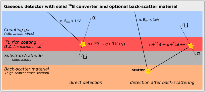
In particular when it comes to instruments where detectors are required to, at a reasonable cost, cover large areas with detectors offering high rate capabilities, modest resolutions and modest to high efficiencies, the perhaps most promising candidate is gaseous detectors surrounded by solid converters in the form of thin films of 10B-enriched boron carbide [8, 9]. The basic principle of a successful direct detection event in the latter is illustrated on the left in fig. 1: after conversion one of the released ions travels into the instrumented counting gas where it can be detected like any energetic charged particle would. Typically the instrumentation would include anode wires, with the boron-carbide itself acting as the cathode, and such a detector therefore has the inherent high-rate capability of any such gaseous detector in proportional mode. Furthermore, due to the higher amount of energy released in the conversion reaction involving 10B (2.3 MeV) compared to the corresponding 3He reaction (0.77 MeV), and the implied large signals, the technology offers the possibility for very high suppression of gamma backgrounds [10] which can otherwise be a problem at neutron instruments. Additionally it is a relatively cheap technology, allowing for large detector coverage when needed. However, the main limitation of the method is that high conversion efficiencies (% several tens of micrometers of converter, whereas the resulting and Li ions only have a reach of a few micrometers in solid materials. Thus, to obtain higher detection efficiencies, one will typically either place many independent layers of gas-facing converters in the neutron path or try to arrange the geometry so as to keep the angle of incidence of the neutron on the converter as high as possible, or a combination of the two111In this paper we adopt the convention that a 0∘ incidence angle correspond to normal incidence, whereas 90∘ correspond to grazing incidence.. Detailed analytical calculations of detection efficiency depending on inclination and converter thickness exist [11]. However, such solutions come at a penalty of increased complexity and cost, and the present paper instead investigates the performance of an alternative approach in which detection efficiency is increased by the addition of a strongly scattering material at the back of the detector.
II Recovering unconverted neutrons through back-scattering
The principle of the method investigated in this paper is simple, as illustrated on the right in fig. 1: Placing a material with high back-scattering cross-section behind a neutron detector will increase detection efficiency, since a neutron which did not convert in the detector in the first place will have a nonzero probability of scattering back to the detector and converting the second time around, thus recovering events which would otherwise go undetected.
Obviously, the downsides to adding such a scattering material would be expected to be two-fold: Not only would the events thus recovered suffer from degraded position resolution as well as a systematic positive shift in detection time, but one would also potentially have to worry about back-scattered neutrons escaping the detector through the front. The latter could potentially be a problem if the instrument in question features detectors at opposite sides of a sample in which neutrons scatter before detection. Collimators in front of the detectors and shielding between detector sections would often be needed in any case, and can be expected to significantly lower the negative impact of this effect. Additionally, if the chosen back-scatter material primarily scatters incoherently, one would avoid unduly adding new features to the detected distributions. Naturally, for any given instrument one would need to carefully analyse the exact implementational details of proposed designs in order to ensure that all such effects would be understood, preferably through a combination of tests on prototypes and simulations of the complete envisioned setup.
The requirement of high cross-sections for incoherent scattering of thermal neutrons suggests that a hydrogen-rich moderator-like material would be a good candidate back-scatter material. From an operational and costing point of view, the most suitable candidate would a priori seem to be a plastic such as the widely used and studied moderator and shielding material, polyethylene (PE), which is therefore the material we will focus on in the present investigations.
Regarding the placement of the back-scatter material, it should ideally be immediately after, or as close as possible to, the last conversion material in the detector. This, in order to reduce the additional time shift and spatial displacement of the back-scattered neutrons before a potential conversion. Furthermore, it is obviously important that any material between the last conversion material and the back-scatter material will have a very low probability of neutron absorption. Finally, it is also clear that multilayered detectors in which the depth-of-interaction is used to estimate the total time-of-flight and hence the energy of the neutron, would not be suitable to be extended with a back-scatter material.
Given the above considerations, the present investigations will focus on the performance impact of adding a layer of polyethylene behind a single-layered 10B-thin film based gaseous detector, as is illustrated in fig. 1. Although not strictly specified by the method, the detector will for simplicity be taken to be implemented as in the figure with a converter-coated aluminium substrate at the backside of the gas only, and with the polyethylene located at the back of the substrate. Obviously, a multilayer setup at an instrument which does not rely on time-of-flight information would also be possible, but in general multilayer setups already come with high detection efficiencies and price tags, and the presently discussed method is likely more suitable for the opposite scenarios.
III Simulations
The exact impact upon instrument and detector performance of adding a back-scatter material to a detector at a neutron scattering instrument will depend in detail on the detector technology and layout, the instrument purpose and the exact integration of the back-scatter material itself into the design. But it is nonetheless possible to evaluate the feasibility of the back-scattering concept by considering a specific and simple, yet reasonably realistic setup. The present investigations will therefore consist of realistic Monte Carlo simulations of a setup exactly like the one depicted in fig. 1, in which layers of counting gas, converter, substrate and possibly a back-scatter material will be placed in the path of incoming neutrons. The layers will be assumed to be very large in the transverse dimensions.
III-A Setup details and validation
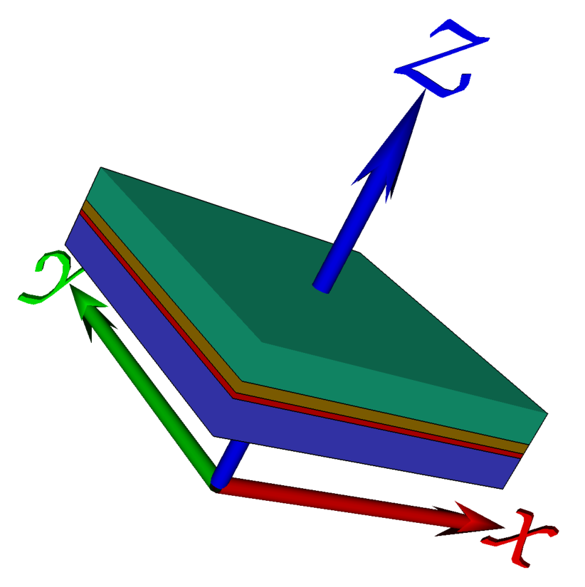
The simulations are implemented and carried out using the Geant4 [12, 13]-based framework described in [14], and the simulated geometry is shown in fig. 2. For reference, the present investigations are implemented in Geant4 version 10.0.3 with a 70% counting gas mixture of Ar-CO2, a boron-carbide converter enriched to 98% 10B, and gas and substrate plane thicknesses of 10mm and 0.5mm respectively. The results are not believed to be sensitive to any of these choices.
Previous studies [15], which also included comparisons with test-beam data, have shown that Geant4 with the QGSP_BIC_HP physics list is able to adequately capture the physics of the neutron absorption in the enriched boron-carbide and the subsequent journey of the released ions into the counting gas. It was also shown that a simple threshold, here chosen to be 150keV, on the amount of energy deposited therein suffices to accurately emulate actual detection efficiencies in a real detector equipped with anode wire-planes in the counting gas. This is of course not surprising, as one would first of all expect Geant4 to describe absorption of thermal and colder neutrons well, given that the relevant cross-sections are given by a simple law. Secondly, because a good description of energy loss by charged particles in matter is an essential feature of Geant4, used as it is to routinely model energy depositions in a broad range of applications.
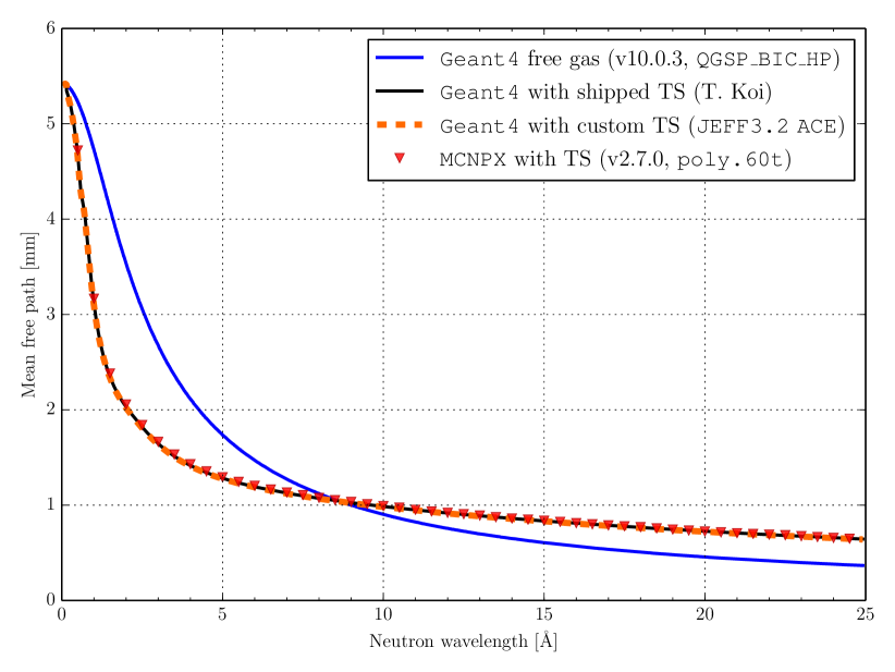
However, materials in Geant4 are usually described under a free-gas assumption, with no information concerning inter-atomic chemical bindings. This means that potentially important features like Bragg-diffraction in a polycrystalline material like aluminium, or thermal scattering (TS) on energy levels in hydrogen bonding in polyethylene are a priori missing. For the former issue, the setup is therefore augmented to use the NXSG4 extension [16], to ensure accurate description of the aluminium used in the substrate. For the latter issue, it is fortunate that polyethylene, seeing significant use for neutron moderation and shielding, is one of a select few materials for which detailed thermal scattering cross-section data at various temperatures exists, although different codes and data versions might provide slightly different results. Here, we will compare a model shipped with Geant4 itself, due to work by T. Koi, with a custom in-house model to evaluate the JEFF-3.2 ACE formatted files for the Thermal Scattering Law [17], as well as, for reference, with output from simulations carried out with MCNPX version 2.7.0 [18] using the poly.60t thermal cross sections derived from ENDF6.5 dynamic structure factors using NJOY [19]. Choosing pragmatically a material temperature of 293.6K which is available for polyethylene in all three implementations, and comparing also with the base free-gas treatment in QGSP_BIC_HP, the resulting mean free path lengths of neutron interactions in polyethylene are shown in fig. 3. Note that for reliability, the values were extracted at run-time rather than second-guessed from data files. For Geant4, this was done via a custom hook querying the physics processes GetMeanFreePath(..) methods. For MCNPX, the values were determined through direct simulations of neutrons impinging on a very thin plane of polyethylene, and the resulting statistical errors are smaller than the plot markers. The importance for our analysis of using specific thermal scattering data for polyethylene, rather than just the base free-gas model is clear, as the resulting mean free path length for neutrons scattering in polyethylene is affected with as much as a factor of 2.
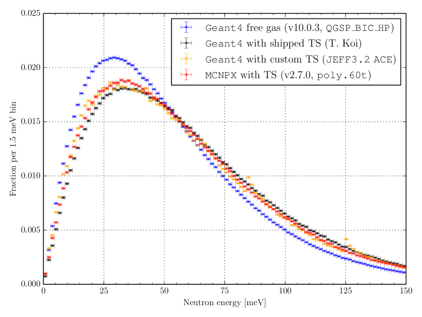
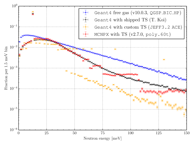
As a further comparison, fig. 4 shows the simulated transmission spectrum of 2.5Å neutrons moderated in a 50mm thick slab of polyethylene. For the purposes of the present investigations, the three curves with specific thermal scattering models are compatible and different from the free-gas model. However, as the present investigations involve back-scattering in potentially very thin layers of polyethylene, it is interesting to compare the back-scattered spectrum after a single interaction. Thus, fig. 5 shows a comparison of the back-scattered spectrum in a 100m polyethylene slab, of which two interesting observations can be made: First of all, the three thermal scattering models all include an incoherent elastic peak at the energy of the incoming neutron (2.5Å 13.1meV), whereas this is absent in the free-gas model. Secondly, whereas it is once again clear that the general shapes of the distributions for the three thermal scattering models follow the same rough shape, it is only the one shipped with Geant4 which does not exhibit artifacts due to the discrete parameterisations of the thermal scattering data, and for that reason this is the model chosen for the investigations in the following sections.
III-B Results
As an illustration, simulated trajectories of particles resulting from firing 50 neutrons into our setup are visualised in fig. 6: neutrons arriving from below travel through the counting gas and either convert in the enriched boron-carbide immediately, releasing charged ions into the gas, or pass onwards through the substrate and into the polyethylene where complex trajectories follow as a result of the multiple scattering interactions. Ultimately those neutrons either pass through to the backside of the polyethylene, get absorbed in processes releasing photons, or return back to the substrate and converter, where some are absorbed the second time around as hoped, again releasing ions into the counting gas.
The key issues to be investigated with the simulations are on one hand what positive impact placing different amounts of polyethylene will have on detection efficiency, and on the other hand what the associated negative impacts on time and position resolution will be, and to what extent those can be mitigated. The answers can be expected to depend also on the angle of incidence of the neutron on the detection plane, the neutron energy and on the chosen thickness of the converter coating. To answer these questions, large numbers of neutrons were simulated for a variety of configurations, and the results subsequently carefully analysed in order to produce the plots in this section. For reference, a total of neutron events were simulated, using between and for each given configuration, as needed to achieve reasonably low statistical fluctuations in all plots.
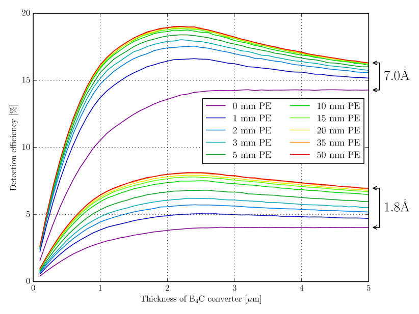
First, simulated detection efficiencies at normal incidence as a function of converter thickness are shown in fig. 7 for various amounts of polyethylene and for both thermal (1.8Å) and cold (7.0Å) incident neutron energies. As expected, detection efficiencies for colder neutrons are higher, but otherwise the qualitative features of the curves are similar to those at thermal energies. For simplicity, the remainder of our investigations will therefore focus on neutrons with a wavelength of 1.8Å. The next thing to notice is that the curves without polyethylene grow monotonically with converter thickness, but effectively saturate at the final plateau already around m, which is the effective range in the converter of the ions released in the conversion. These converter thicknesses compare well to the expectation from the analytical calculations [11], lending further credence to the simulation. On the other hand, when polyethylene is added, the curves exhibit a maximum around 2.1–m, which is expected since conversions at ever deeper locations are increasingly unlikely to contribute positively with direct detection events, and will merely act as unwanted inactive shielding in the path of neutrons being back-scattered by the polyethylene. Fortunately, it appears that all curves are reasonably close to their maximum value when the converter thickness is set to m, allowing for the simplifying assumption of using this value throughout the remainder of the investigations, without unduly biasing the comparisons. Finally, it appears as could be expected that detection efficiencies only grow with the amount of polyethylene added, but at an ever decreasing rate — the biggest gain coming from the first few millimetres added.
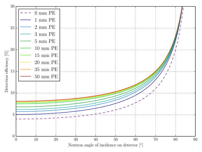
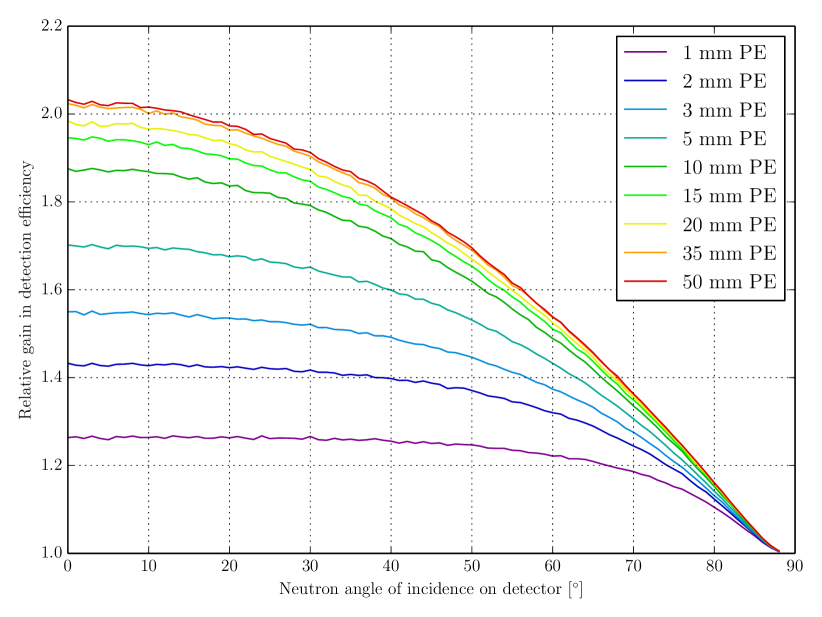
Next, fig. 8 shows the detection efficiency as a function of incidence angle of the neutron on the detector planes. Naturally, the efficiency curves all increase sharply as the incoming neutron tend towards grazing incidence. However, as is seen more clearly in fig. 9, the relative gain in detection efficiency from adding the polyethylene decreases at higher incidence angles. This is easily understood since the back-scattering from the polyethylene is incoherent and thus effectively isotropic: at low incidence angles a random back-scattered neutron is likely to hit the converter at a higher incidence than during the initial traversal, whereas at high incidence angles the situation is reversed. Thus, while the result of fig. 9 is promising very tangible improvements at low incidence angles, it is also making it clear that the concept is not suitable for detectors which are to be operated at higher incidence angles. For that reason, the rest of the present investigations will focus on neutrons with low incidence angle (perpendicular to the surface).
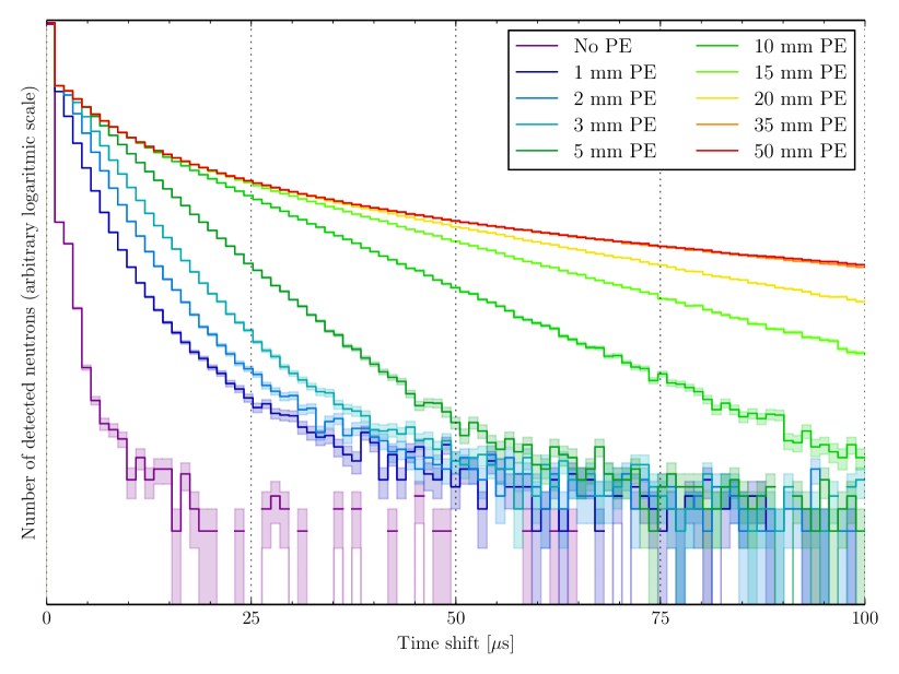
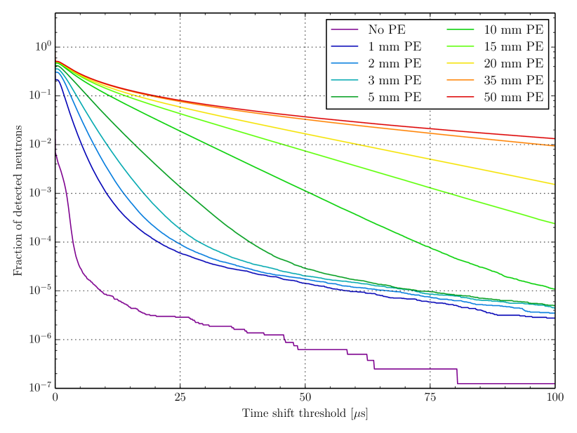
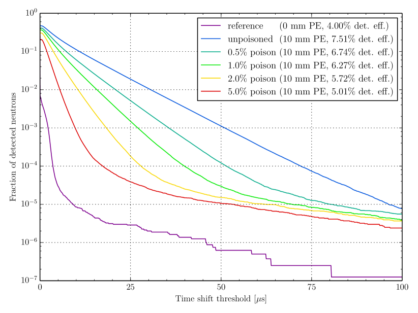
Turning to the possible downsides, fig. 10 shows the distribution of simulated detection time for various amounts of polyethylene, counting from the moment the neutron first enters the converter and until the time when energy exceeding the threshold is deposited in the countring gas, usually by the released ions. It is clear that addition of polyethylene behind the detector leads to increasing tails towards larger times, but in order to quantify the effects it is arguably more useful to look instead at the curves showing the fraction of neutrons with detection time shifts above a given threshold shown in fig. 11. For instance, one can learn that if a specific detector has a requirement that all except of the detected neutrons must be detected with a time shift less than 50s, one should not add more than 10mm of back-scattering polyethylene. Fortunately, even a 100s resolution at the level would be adequate for many neutron instruments [7].
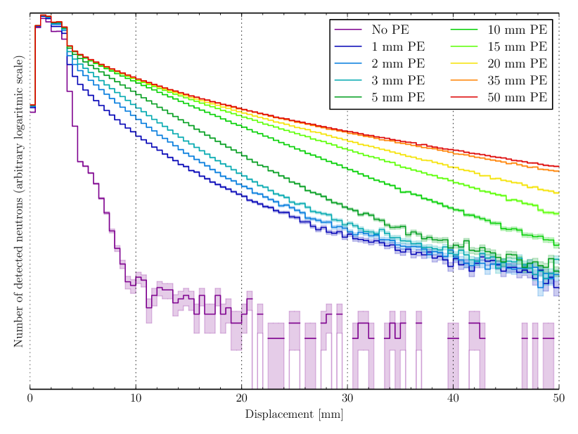
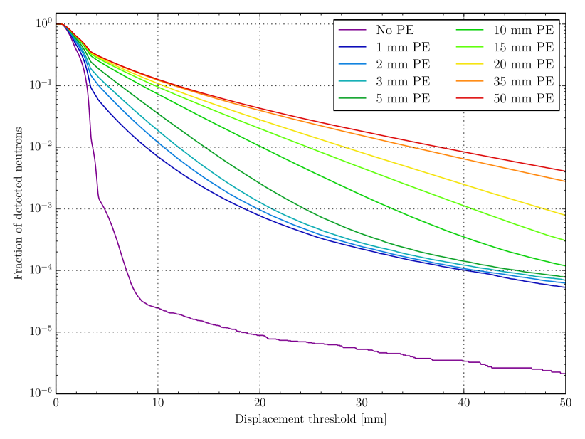
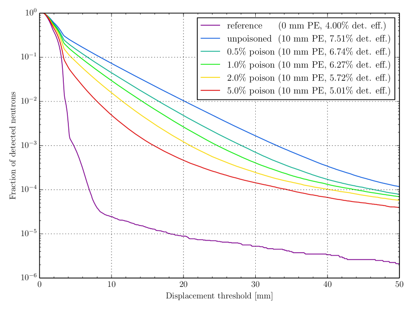
Next, fig. 12 and fig. 13 show the corresponding distributions of the spatial displacement of the detection location, given by the location of energy depositions in the counting gas, relative to the position where the neutron first enters the converter. Again we can readily read of performance metrics from the second of the figures: If one requires all except of neutrons to be detected with a displacement less than 20mm, no more than 10mm of polyethylene should be added behind the detector.
III-C Possible mitigation strategies
The results so far, summarised in fig. 9, 11 and 13, indicate that the presented method has the potential to provide substantial gains in detection efficiencies, but with potentially significant associated adverse effects on both temporal and spatial detection resolutions. In this section we will briefly investigate two strategies for reducing the impact of these adverse effects. In essence, both will try to eliminate some or all unfavourable trajectories in the polyethylene, while hopefully retaining a large fraction of the beneficial ones. Ignoring events with neutrons either absorbed inside or transmitted through (to an absorbing backside most likely) the polyethylene, favourable trajectories are obviously those where the neutron is back-scattered out of the front of the polyethylene with as small a distortion of distance and time as possible. Unfavourable trajectories are on the other hand those where the neutron either spends a long time inside the polyethylene (impacting temporal detection), or travels a long transversal distance inside the polyethylene (impacting spatial detection).
To eliminate the first type of unfavourable trajectories, one might consider “poisoning” the polyethylene, by contaminating it with a small fraction of atoms with high cross-section for neutron absorption. Done right, this should ideally result in a large fraction of those neutrons spending a long time inside the polyethylene being absorbed, with only little impact on neutrons promptly back-scattered. To quantify the potential of poisoning, fig. 14 shows the simulated effect in a setup with 10mm polyethylene. For example, adding 0.5% reduces the fraction of neutrons detected above 50s by an order of magnitude, while only reducing the detection efficiency from 7.51% the reference 4% potentially very potent method, if one is concerned with the detection time resolution. On the other hand, fig. 15 shows that the impact on the spatial resolution is somewhat smaller, which is as expected since the unfavourable trajectories travelling a long transversal distance in the polyethylene are not necessarily always spending a very long time in it.
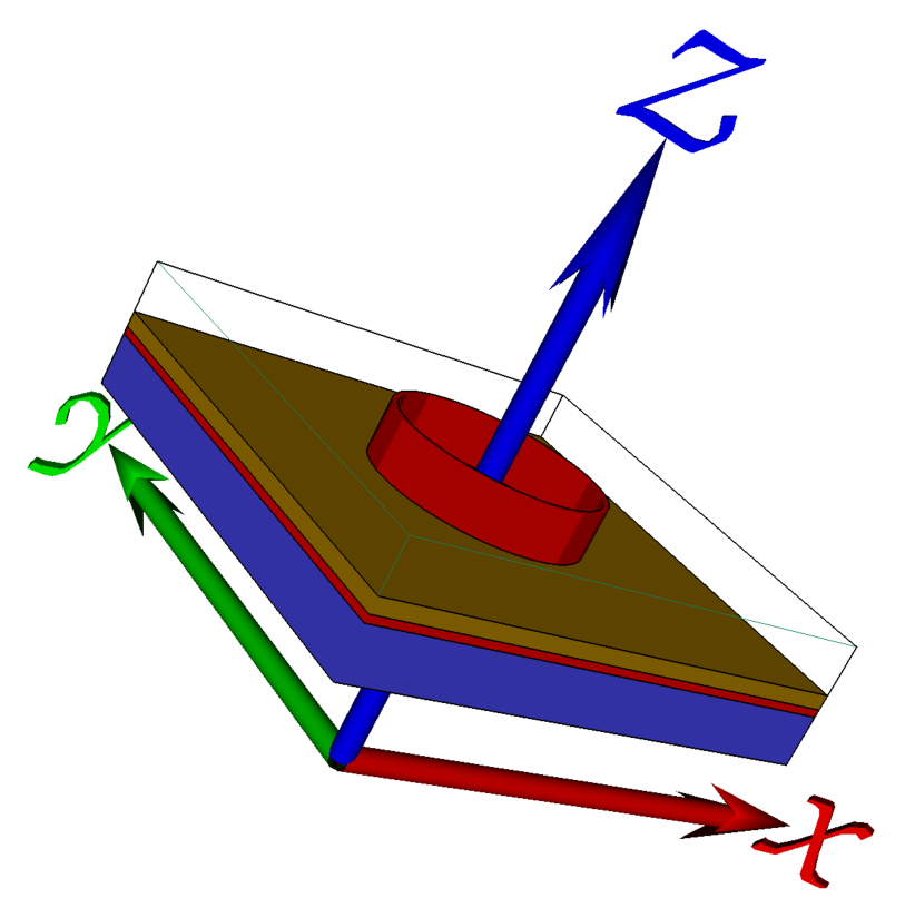
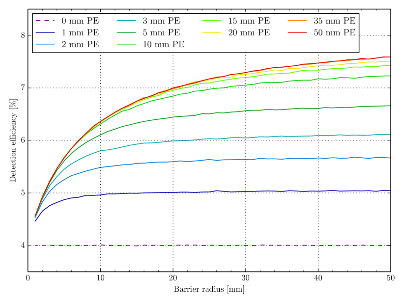
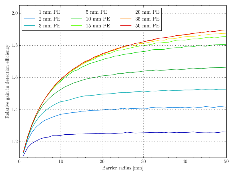
Fortunately, tails in the spatial resolution are easily handled in the context of real detectors, which are typically segmented according to their required granularities, charge collection and readout schemes. Thus, by segmenting the polyethylene as well, separating different detector cells by appropriate absorbing material, one can be certain that a neutron entering the polyethylene from within a given cell, will only be able to be back-scattered to the same detection cell. The question then instead becomes one of how much the detection efficiency gain due to the polyethylene will be reduced due to neutrons meeting the absorber between polyethylene cells. This will again depend on the exact detector design, but to quantify the effect and the dependency on the size of detection cells, simulations were carried out with a cylindrical barrier of 100m enriched boron-carbide placed in the polyethylene as shown in fig. 16, and detection efficiencies were simulated for neutrons at normal incidence generated uniformly over the corresponding circular detection cell. The result is shown in fig. 17 and 18: For very small detection cells, the absorption in the barrier almost completely elliminates the gain from adding the polyethylene, but for a realistic barrier radius of 20mm, 10mm of polyethylene will still provide a relative gain in detection efficiency of approximately 70%
IV Conclusion
The concept of enhancing effective detection efficiencies of neutron detectors by placing a strongly scattering material at their backside was presented, and investigated through analysis of Geant4 simulations in the scenario of polyethylene placed behind a single-layer thin-film detector. The method shows great promise in the case of neutrons at low angle of incidence (close to perpendicular to the Boron coating), but care must be taken to keep the potential adverse consequences of the extra scatterings under control, possibly via one of the investigated mitigation strategies.
References
- [1] S. Peggs et al., “ESS Conceptual Design Report, ESS 2012-001,” http://europeanspallationsource.se/scientific-technical-documentation, 2012.
- [2] ——, “ESS Technical Design Report, ESS 2013-001,” http://europeanspallationsource.se/scientific-technical-documentation, 2013.
- [3] A. Cho, “Helium-3 shortage could put freeze on low-temperature research,” Science, vol. 326, no. 5954, pp. 778–779, 2009.
- [4] T. M. Persons and G. Aloise, “Technology Assessment: Neutron Detectors: Alternatives to Using Helium-3, ,” 2011, GAO-11-753.
- [5] K. Zeitelhack, “Search for alternative techniques to Helium-3 based detectors for neutron scattering applications,” Neutron News, vol. 23, no. 4, pp. 10–13, 2012.
- [6] International Collaboration for the Development of Neutron Detectors, http://www.icnd.org/.
- [7] O. Kirstein et al., “Neutron Position Sensitive Detectors for the ESS,” Proceedings of Science (Vertex 2014), p. 029, 2014.
- [8] C. Höglund et al., “B4C thin films for neutron detection,” J. Appl. Phys, vol. 111, p. 104908, 2012.
- [9] K. Andersen et al., “10B multi-grid proportional gas counters for large area thermal neutron detectors,” Nucl. Instrum. Meth. A, vol. 720, no. 0, pp. 116 – 121, 2013.
- [10] A. Khaplanov et al., “Investigation of gamma-ray sensitivity of neutron detectors based on thin converter films,” Journal of Instrumentation, vol. 8, p. P10025, 2013.
- [11] F. Piscitelli and P. V. Esch, “Analytical modeling of thin film neutron converters and its application to thermal neutron gas detectors,” Journal of Instrumentation, vol. 8, p. P04020, 2013.
- [12] S. Agostinelli et al., “GEANT4: A Simulation toolkit,” Nucl. Instrum. Meth., vol. A506, pp. 250–303, 2003.
- [13] J. Allison et al., “Geant4 developments and applications,” IEEE Trans. Nucl. Sci., vol. 53, p. 270, 2006.
- [14] T. Kittelmann et al., “Geant4 based simulations for novel neutron detector development,” J. Phys: Conf. Ser., vol. 513, p. 022017, 2014.
- [15] I. Stefanescu et al., “Development of a novel macrostructured cathode for large-area neutron detectors based on the 10B-containing solid converter,” Nucl. Instrum. Meth. A, vol. 727, no. 0, pp. 109 – 125, 2013.
- [16] T. Kittelmann and M. Boin, “Polycrystalline neutron scattering for Geant4: NXSG4,” Computer Physics Communications, vol. 189, no. 0, pp. 114 – 118, 2015.
- [17] A. J. Konig et al., “Status of the JEFF Nuclear Data Library,” J. Korean Phys. Soc., vol. 59, no. 2, pp. 1057–1062, 2011.
- [18] D. B. Pelowitz et al., “MCNPX 2.7.0 Extensions,” Los Alamos National Laboratory, Tech. Rep. LA-UR-11-02295, 2011.
- [19] R. E. MacFarlane et al., “The NJOY Nuclear Data Processing System, Version 2012,” Los Alamos National Laboratory, Tech. Rep. LA-UR-12-27079, 2012.