Overlap Frequency Domain Equalization for Faster-than-Nyquist Signaling
Abstract
This letter proposes the Faster-than-Nyquist signaling (FTNS) using overlap frequency domain equalization (FDE), which compensates the inter-symbol interference (ISI) due to band limiting filters of the FTNS at the transmitter and the receiver as well as the frequency selective fading channel. Since overlap FDE does not require any guard interval (GI) at the transmitter such as cyclic prefix (CP), higher spectral efficiency can be achieved compared to FTNS scheme using the conventional FDE. In the proposed method, the equalizer weight is derived based on minimum mean square error (MMSE) criterion taking the colored noise due to the receiving filter into consideration. Moreover, we also give an approximated FDE weight in order to reduce the computational complexity. The performance of the proposed scheme is demonstrated via computer simulations.
Index Terms:
Faster-than-Nyquist signaling, Overlap frequency domain equalization, Inter-symbol interference, Minimum mean-square-error, Colored noise.I Introduction
Faster-than-Nyquist signaling (FTNS) [1] [2] is considered as one of key technologies for the fifth generation (5G) mobile communications systems [3]. FTNS can increase the transmission rate without increasing the required frequency bandwidth by transmitted modulated symbols with the rate faster than the Nyquist rate, which ensures inter-symbol interference (ISI)-free transmission in band limiting channels. It has been analytically shown that the minimum Euclidean distance between sequences of binary phase shift keying (BPSK) symbols using sinc-pulse does not degrade even with the rate 25% faster than Nyquist rate. This means that, if the maximum likelihood sequence estimation (MLSE) is employed at the receiver, transmission rate can be increased by 25% without the degradation of the bit error rate (BER) performance. However, the MLSE requires high computational complexity, especially, when the ISIs due to the transmitting/receiving filters as well as the frequency selective fading channel are simultaneously compensated.
To reduce the complexity, the FTNS receiver using frequency domain equalization (FDE) [4] has been recently proposed as a sub-optimal method in [5]. Moreover, the idea of [5] has been extended to the method using frequency domain decision-feedback equalizer in [6]. Furthermore, the FDE-aided soft decision and the multistage serially concatenated turbo architecture are applied for the FTNS demodulator in [7]. However, these conventional FDE-based receivers require the insertion of the guard interval (GI) such as cyclic prefix (CP) at the transmitter, which results in the reduction of the effective transmission rate. Moreover, the colored noise, which is inherent in the received signal of the FTNS, is not explicitly considered in [5] and [7], while [6] takes the colored noise into consideration but with the limitation that the sampling rate at the receiving filter is assumed to be twice the symbol rate in the formulation.
This letter proposes an FTNS transceiver using overlap FDE [8][9], which has been originally proposed for the FDE systems with insufficient CP or without CP. Since the overlap FDE does not require the insertion of any CP at the transmitter at the cost of slight increase in computational complexity at the receiver, the proposed scheme can improve the spectral efficiency with the moderate complexity. Also, we adopt the FDE weight based on minimum mean square error (MMSE) criterion in order to take into account for the impact of the colored noise, and derive approximated one-tap FDE weight to reduce the computational complexity for the equalization. Computer simulation results show that there is a significant difference in BER performance between the receivers using FDE weights with and without considerations of the impact of the colored noise. Moreover, we show that the proposed method can achieve better BER performance than that of the FTNS transceiver using conventional FDE with CP [5] for a fixed transmission rate. In addition, we demonstrate that the proposed scheme can achieve 30% higher transmission rate than that of Nyquist rate without performance degradation, when root raised cosine (RC) filter with the roll off factor of 0.5 is used for transmitting and receiving filters.
II System Model
Fig.1 shows the configuration of the FTNS transmission system model considered in this letter. The transmitted symbol is generated by baseband modulation with PSK (Phase Shift Keying) or QAM (Quadrature Amplitude Modulation) using the binary sequence from the data source. We assume and , where represents the expectation, superscript a complex conjugate, and Kronecker delta. The sequence of is transmitted after passing through the transmitting filter at the interval of . Here, we assume to be the root Nyquist filter with , and satisfies the Nyquist criterion for the symbol period of of . In FTNS, in order to increase the transmission rate, is set to be less than . Thus, we have .
The received signal after matched-filtering with is given by
| (1) |
where is the impulse response of channel including the impact of the frequency selective channel and transmitting/receiving filters and is given by
| (2) |
and is the noise component given by
| (3) |
where the white noise follows the complex-valued Gaussian distribution . The received signal is sampled with the sampling period of , which is the same as the symbol period, then the th sample is given by
| (4) |
where and . Note that the mean and the correlation of the sampled noise are given by and , respectively.

III Proposed FTNS Receiver with Overlap FDE
In the proposed method, overlap FDE [8],[9],[11] is employed to compensate ISIs caused by band limiting filters (i.e., transmitting and receiving filters) as well as the frequency selective channel. Since overlap FDE performs equalization with block-wise signal processing at the receiver, while the transmitted signal need not be block-wise, we firstly give a block representation of the received signal. Assuming that for as in [5] by truncating tails of the impulse response, a received signal block of size defined as , where the superscript T represents the transpose, is given by
| (5) |
where
| (6) |
and
| (7) |
Also, and , where and are the smallest integer not less than and the largest integer not greater than , respectively. In addition, and .
By defining , (5) can be rewritten as
| (8) |
It should be noted here that is a circulant matrix, which can be diagonalized by using -point DFT (discrete Fourier transform) matrix , whose element is , as , where the superscript H denotes Hermitian transpose and is a diagonal matrix whose diagonal elements are the DFT of the first column of . Thus, if we apply FDE for ignoring the second term of right hand side of (8), which represents inter-block interference and ISI components due to the lack of CP, the FDE output is given by
| (9) |
where is an FDE weight matrix.
Since it is empirically known that head and tail of the signal block at the FDE output suffer from the residual interference due to the second term of (III), only the middle part of is used as the output of overlap FDE. Specifically, discarding elements from the head and elements from the tail, the output of the overlap FDE is given by
| (10) |
where is the size of the overlap FDE output, represents the identity matrix of size and a zero matrix of size . The next block processing is performed for the received signal block of in the same way as described above.
Then, we consider the FDE weight based on MMSE criterion. If we ignore the second interference term in (8), the MMSE-FDE weight can be obtained by solving the following optimization problem:
| (11) |
The MMSE-FDE weight is obtained as
| (12) |
Note that since is not diagonal due to the colored noise, is also non-diagonal. Thus, MMSE-FDE is not achieved with one-tap FDE, which may spoil the motivation to utilize FDE because of the high computational complexity.
In order to reduce the complexity, the proposed FTNS scheme obtains the FDE weights by approximating with a diagonal matrix, whose diagonal entries are the same as those of . Then, the approximated FDE weight of can be given by
| (13) |
where is a diagonal matrix composed by the power spectrum density of the noise
| (14) |
IV Simulation results
We evaluate the BER performance via computer simulations in order to confirm the effectiveness of the proposed method. In all the simulations, binary PSK is employed for baseband modulation, and root RC filter with roll off factor 0.5 is used for transmitting and receiving filters. Thus, the Nyquist rate corresponds to [bps/Hz]. For FTNS, transmission rates are set to be (0.73 [bps/Hz]), (0.80 [bps/Hz]), (0.87 [bps/Hz]) and (0.93 [bps/Hz]) higher than the Nyquist rate. We evaluate the averaged BER by counting error using symbol by symbol detection after compensating ISI. The DFT size of FDE is set to be 512 and, in the block processing at the receiver, is truncated with .
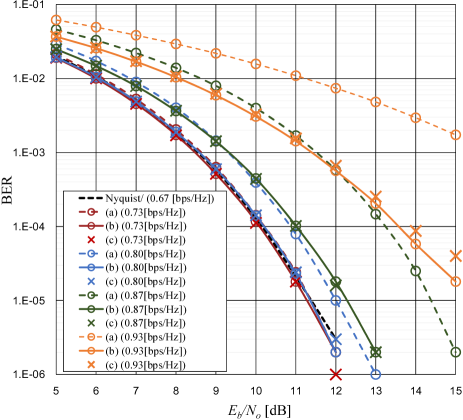
In order to confirm the impact of the colored noise, we firstly compare the BER performance of FTNS transmissions in AWGN (Additive White Gaussian Noise) channel using FDE with CP of length 20 symbols for different FDE weights in Sect.III, i.e., , and . Fig. 2 shows the BER performance against . Here, is set to be , which respectively correspond to rates of [bps/Hz], where the rate loss due to CP is taken into consideration. From Fig. 2, we observe the BER performance of (b) is significantly better than that of (a) for the same transmission rate especially for smaller , which implies the importance to consider the impact of the colored noise. Also, we can observe that (c) can achieve comparable performance to (b) for the same transmission rate, which demonstrates the validity of the approximation in the derivation of (c).
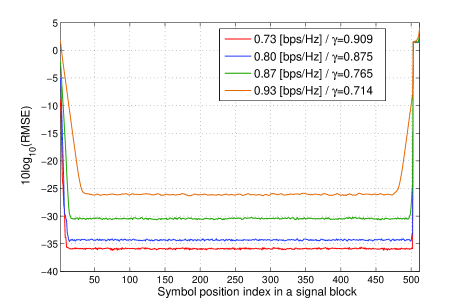
Then, we demonstrate the validity of the proposed approach using overlap FDE for the FTNS transmission. Fig. 3 shows the root MSE (RMSE) between the FDE output using the weight (c) and the actual transmitted symbol averaged over 1,000 FDE outputs versus the symbol position in a signal block, where the additive noise power is set to be 0 and the channel is flat with a fixed gain of 1. Here, is set to be , which correspond to rates of [bps/Hz], respectively. From the results, we can see that RMSE values at the middle part of the block are significantly smaller than the head and the tail of the block for all the values of , and that we only have to remove rather small portions of the FDE output, which means the increase in computational complexity at the receiver due to the employment of overlap FDE is rather limited.
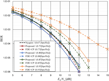
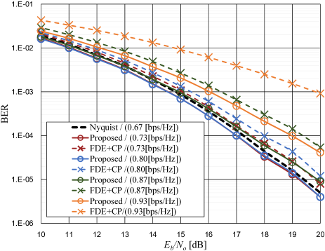
Figs. 4 and 5 show the BER performance of the proposed FTNS scheme using overlap FDE in AWGN channel and 10-tap frequency selective Rayleigh fading channel having maximum duration of , respectively, for different values of used in Fig. 3. Also, the performance of FTNS using FDE with CP [5] is also plotted in the same figures for a comparison purpose. In both schemes, the FDE weight of (c) is employed to cope with the colored noise, while (a) is used in the original scheme in [5]. In the proposed FTNS scheme, and are set to be for the AWGN channel and for the frequency selective fading channel. In the scheme using FDE with CP, the length of CP is set to be 20 for the AWGN channel and 36 for the frequency selective fading channel, and is set to be for the AWGN channel and for the frequency selective fading channel, which results in the same effective transmission rates as those of the proposed FTNS scheme. From the results in Figs. 4 and 5, we can observe that the proposed FTNS scheme can achieve better BER performance than that of the scheme in [5] for the same rate. Moreover, in both figures, the BER performance of the proposed FTNS scheme with the rate less than or equal to 0.87 [bps/Hz] is comparable to that of the Nyquist rate transmission, which means that higher transmission rate than the Nyquist rate transmission can be achieved with the proposed FTNS scheme without BER performance degradation if root RC filter with roll off factor 0.5 is employed for transmitting and receiving filters.
V Conclusion
In this letter, we have proposed the ISI compensation method using overlap FDE for FTNS transmission. In order to take account for the impact of colored noises due to receiving filter, we have proposed an approximated MMSE weight for the one-tap FDE. Computer simulation results show that the colored noise should be explicitly considered in the FTNS using FDE. Moreover, we have confirmed that, with the proposed scheme, 30% higher rate than the Nyquist rate can be realized without BER degradation root RC filter having roll off factor 0.5 is used as band limiting filters.
Acknowledgements
This work was supported in part by JSPS KAKENHI Grant Number 15K06064.
References
- [1] J. E. Mazo, “Faster-Than-Nyquist signaling,” Bell Syst. Tech. J., vol. 54, no. 8, pp. 1451-1462, Mar. 1975.
- [2] J. B. Anderson, F. Rusek and V. Öwall, “Faster-than-Nyquist signaling,” Proc. IEEE, vol. 101, no. 8, pp. 1817-1829, Aug. 2013.
- [3] A. Osseiran etal.“Scenarios for the 5G mobile and wireless communications: the vision of the METIS project,” IEEE Commun. Mag., vol. 52, no. 5, pp. 26-35, May 2014.
- [4] D. Falconer, S. L. Ariyavisitakul, A. Benyamin-Seeyar, and B. Eidson, “Frequency domain equalization for single-carrier broadband wireless systems,” IEEE Communication Magazine, vol. 40, no. 4, pp. 58-66, Apr. 2002.
- [5] S. Sugiura, “Frequency-domain equalization of faster-than-Nyquist signaling,” IEEE Wireless Communications Letters, vol. 2, no. 5, pp. 555-558, Oct. 2013.
- [6] S. Tomasin and N. Benvenuto, “Fractionally spaced non-linear equalization of faster than Nyquist signals,” Proc. of the 22nd EUSIPCO, pp. 1861-1865, Sep. 2014.
- [7] S. Sugiura and L. Hanzo, “Frequency-domain equalization aided iterative detection of faster-than-Nyquist signaling,” IEEE Trans. Veh. Technol., in press.
- [8] I. Martoyo, T. Weiss, F. Capar, and F. K. Jondral, “Low complexity CDMA downlink receiver based on frequency domain equalization,” IEEE Vehicular Technology Conference, vol. 2, pp. 987-991, Sept. 2003.
- [9] C. V. Sinn, and J. Götze, “Avoidance of guard periods in block transmission systems,” IEEE Workshop, SPAWC, pp.432-436, Jun. 2003.
- [10] W. Mike, and L. Grobe, “Block transmission with frequency domain equalization in the presence of colored noise,” Proc. of International Conf. on Transparent Optical Networks, pp.1-4, Jun. 2011.
- [11] W. Bocquet, K. Hayashi and H. Sakai, “Systematic design of single carrier overlap frequency domain equalization,” Journal of Systems Science and Complexity, vol. 23, no. 1, pp. 50-60, Feb. 2010.