Software design for the control system for Small-Size Telescopes with single-mirror of the Cherenkov Telescope Array
Abstract:
The Small-Size Telescope with single-mirror (SST-1M) is a 4 m Davies-Cotton telescope and is among the proposed telescope designs for the Cherenkov Telescope Array (CTA). It is conceived to provide the high-energy ( few TeV) coverage. The SST-1M contains proven technology for the telescope structure and innovative electronics and photosensors for the camera. Its design is meant to be simple, low-budget and easy-to-build industrially.
Each device subsystem of an SST-1M telescope is made visible to CTA through a dedicated industrial standard server. The software is being developed in collaboration with the CTA Medium-Size Telescopes to ensure compatibility and uniformity of the array control. Early operations of the SST-1M prototype will be performed with a subset of the CTA central array control system based on the Alma Common Software (ACS). The triggered event data are time stamped, formatted and finally transmitted to the CTA data acquisition.
The software system developed to control the devices of an SST-1M telescope is described, as well as the interface between the telescope abstraction to the CTA central control and the data acquisition system.
1 Introduction
The Cherenkov Telescope Array (CTA) observatory is conceived to be the largest observatory for the Very High Energy (VHE) gamma rays, exploring energies from to few hundreds of TeV. To span such energies, three different kind of telescopes are proposed: Large-Size Telescopes (LST) to cover from to , Medium-Size Telescopes (MST) from to and Small-Size Telescopes (SST) to measure above few TeV.
Among the SST projects, the Small-Size Telescopes with single-mirror (SST-1M) is a 4 m Davies-Cotton telescope, which comprises proven technology for the telescope structure, and innovative electronics and photosensors for the camera. Its design is meant to be simple, low-budget and easy-to-build industrially[1]. The construction of the prototype is progressing rapidly and the first run is expected for September 2015.
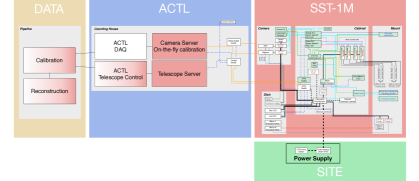
In the meantime, the software to connect the control system of the telescope to the whole array of CTA is under development. The whole array is controlled by the Central Array Control System (ACTL)[2], based on the ALMA Common Software (ACS) framework[3, 4]. It is the highest level of control and provides an abstract interface to the telescopes with configuration, logging and control services. The general view of the data flow between the SST-1M abstraction and the ACTL is shown in Figure 1. The abstraction divides the telescope object (SST-1M block in the figure) into five device subsystems, discussed in detail in Section 2: Active Mirror Control (AMC), CCD Camera (CCD), Programmable Logic Controller (PLC), Camera Server (CS) and Camera Slow Control (CSC).
The preferred policy for the ACTL is to have a native Open Platform Communications Unified Architecture (OPC-UA) for each device. It is an industry standard communications protocol that uses an information model based on a full-mesh network of nodes. All the devices are visible through OPC-UA servers, for which every device command and data point can be seen as nodes. Through a Java bridge, the nodes of the server are translated into object for the ACS framework, which can be written in Java, C++ or Python languages. This framework enwraps subsystems, called components, to abstract the telescope as a single object. However a native OPC-UA is not always available. In this case, it is possible to interface to a device directly via the ACS component.
The whole software is developed in a common operating system for the whole CTA consortium: a virtual machine with a Scientific Linux 6.
2 Software status for the device subsystems
2.1 Active Mirror Control
The AMC is an interactive system to align the mirror facets mounted on the mirror dish[1] with a precision of m. Each of the 18 facets has a set of two actuators for the and movement that can be moved with independent speeds specified by the user.
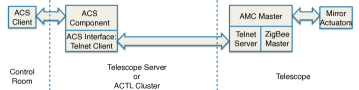
Each facet uses a telnet connection through a ZigBee master with a single IP address. No native OPC-UA is provided, thus the interface to telnet is performed directly via ACS components written in Java language. The pipeline is schematized in Figure 2. The ACS component is completed and in beta-phase. Moreover, the software of the AMC is used to test the skeleton of the web GUI, explained in Section 2.6.
2.2 CCD Camera
SST-1M has 3 different CCDs: “Sky CCD”, “LidCCD” and “Surveillance CCD”[1]. The SkyCCD, used for the pointing, is mounted on a side of the dish support structure and provides an image of the sky with stars. The LidCCD, also mounted on the dish support structure but in the optical axis of the telescope, provides an image of the stars reflected on the camera lid and images of the pointing LEDs mounted in the camera focal plane. This camera is also used by the mirror alignment system. The Surveillance CCD is a surveillance camera.
All three CCDs are similar to the ones utilized by MST, with the same software[5] adapted for the SST-1M case. The software will control the image taking, image archiving and also slow control of the CCD Camera (power switching, temperature monitoring, error reporting). It also allows to identify the bright spots in the image (stars or LEDs images), the stars and their coordinates, and to calculate the required pointing calibration corrections. The ACS component, written in Java language, communicates directly with the device, is fully functional and has been used continuously since almost two years in the MST prototype. The adaptation to SST-1M will be finalized by July 2015.
2.3 Camera Server
The CS plays an important role in the bulk data reception[1]. It consists of a Camera Server hardware and Camera Server software. It interfaces directly with the camera through DigiCam (via 10 Gbit/s link), the ACTL and Data Acquisition System (DAQ) (10 Gbit/s link), the Clock Distribution and Trigger Timestamping (CDTS) (1 Gbit/s link), the Software Array Trigger (SWAT) (1 Gbit/s link). DigiCam is the camera Digital Trigger Readout System of SST-1M[1]. It controls the Photon Detection Plane (PDP), as will be discussed in Section 2.4. The SWAT system checks which data are part of the triggered array and can be sent to the DAQ[2]. CDTS synchronizes and forwards the timestamp with a nanosecond precision, and provides an absolute clock with a s precision[2].
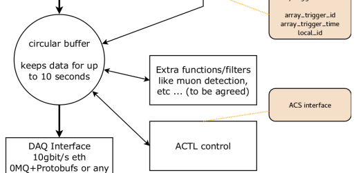
When the bulk data packets are received, they are assembled into complete local camera triggered events and stored in memory for up to 10 s in a circular buffer. The local event building verifies the proper sequencing of the packets, checks for data completeness, and filters out any duplicated, late, out-of-sync or erroneous packets. The timestamps are either embedded in the bulk data (if a native DigiCam WhiteRabbit (WR)111The WhiteRabbit is the common clock system of CTA, which provides time-stamps with sub-nanosecond precision that are used to associate data to telescope events[6, 7]. interface is used), or read from CDTS (if an UCTS board is used, as for current recommendation by the ACTL developer group), and verified. Then CS interfaces with the SWAT, which replies on whether the local trigger is a member of an array trigger, part of any calibration or a special event. In the positive case, the data are forwarded to the DAQ and the buffer is emptied. In the negative case, the stored information is discarded. In Figure 3 such a scheme is shown.
The Camera Server software tasks use the following communication protocols:
-
•
for reception: the foreseen wire protocol is UDP jumbo packets; the exact contents of the packets are still to be finalized;
-
•
for assembly: the DigiCam local camera triggered event size is about 64 Kbyte, which requires several UDP jumbo packets;
- •
2.4 Camera Slow Control
The CSC manages the PDP and is able to read the signals, temperature and set the bias Voltage for each single Silicon Photomultiplier (SiPM)[1]. The read signal is sent and processed by DigiCam, which digitizes it through a Fast Analog to Digital Converter (FADC) with a sampling duration of 4 ns and applies the local camera trigger logic. If the event triggers the telescope camera, DigiCam will communicate with the Camera Server as explained in Section 2.3. Moreover, since the operational point of the SiPMs depends on their temperature, the CSC provides a compensation loop algorithm that reads the temperature and adjusts the bias Voltage accordingly.
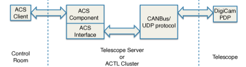
The CSC uses a CANBus integrated in the DigiCam, which communicates and sends commands to the PDP via UDP connection. The CSC does not have a native OPC-UA, therefore the connection to the CANBus will be performed directly via ACS components. Finally, the CANBus software drivers are provided with Python modules, thus the chosen language for ACS is Python. Such a pipeline is schematized in Figure 4.
2.5 Programmable Logic Controller
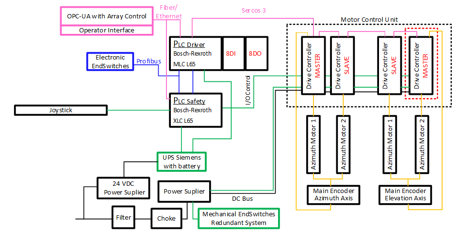
SST-1M has two different PLCs. The main one (also called “drive”, dPLC) is very similar to the MST PLC and uses the same software[5]. The auxiliary one is specific for this telescope is called Safety Programmable Logic Controller (sPLC)[1]. It has embedded the Profibus and Sercos III communication interfaces. It supports signal modules as digital and analog inputs/outputs. The tasks of the sPLC are to control the power supply of the main PLC and to guarantee a safe parking procedure that protects the camera from day light and mechanical damage.
In the case that the main PLC fails or loses connection with the control room, the sPLC will perform a safe parking. In the case of failure of all the encoders (embedded in the servo drives and mounted on the main axes), the Sercos III communication interface is used to support a second redundant parking procedure. This procedure uses the electrical limit switches mounted in appropriate limit positions. These switches are connected to the sPLC with the Profibus gateway, which conducts the parking procedure according to the industrial homing method. Firstly, the homing of the azimuth axis is performed, driving the telescope to the azimuthal park position with some declared initial velocity. When the position is reached, the axis is moved again in the opposite direction with 10% of the velocity for 2 seconds, and then moved back to the parking position once more with 1% of the speed. In this way the accuracy of axis homing is . After the azimuth reaches the parking position, the same procedure is performed for the elevation, taking into account the protection of the camera from damages. Electrical and communication interfaces are shown in Figure 5.
The sPLC software development is in an advanced stage and expected to be completed by August 2015. The first tests were successfully done with a remote connection from Geneva222The telescope prototype is sited in the Instytut Fizyki Ja̧drowej im. H. Niewodniczańskiego Polskiej Akademii Nauk, Kraków, Poland. The PLCs are visible to the ACTL via a native OPC-UA server interface. The ACS components to enwrap the OPC-UAs are in a development phase and are adapted from the MST software written in Java language.
2.6 GUI for the prototype
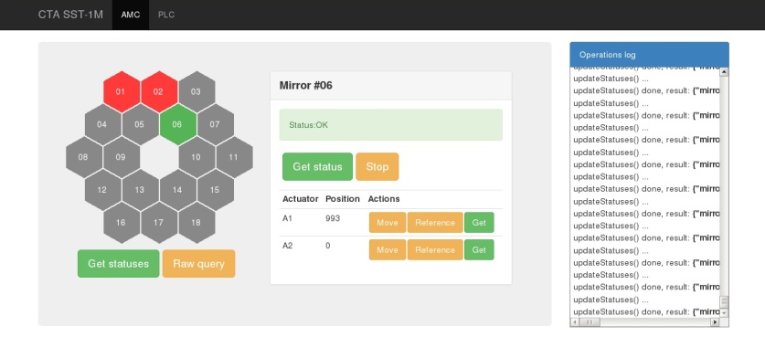
To be able to control the telescope prototype, a web interface GUI is created. This interface will not be part of the ACTL, but the sole purpose is to test the control of the subsystems and the telescope abstraction before they will be delivered to the ACTL interface. The web interface is an HTML page that communicates with the ACS components via a Java client. So far, only the AMC (Section 2.1) is dialoging with the GUI and is used to test it. A screenshot of the GUI is shown in Figure 6.
3 Conclusions
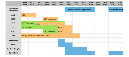
The summary of the planned schedule described so far is shown in Figure 7. The software development tasks are split into those for the ACS components of the ACTL interface (yellow areas) and the control of the device low-level hardware (green areas). In blue the planned operations for the telescope deployment are indicated to be compared with the software development schedule.
Acknowledgements
We gratefully acknowledge support from the agencies and organizations listed under Funding Agencies at this website: http://www.cta-observatory.org.
In particular we are grateful for support from the NCN grant DEC-2011/01/M/ST9/01891 and the MNiSW grant Nr 498/1/FNiTP/FNiTP/2010 in Poland and the University of Geneva and the Swiss National Foundation in Switzerland.
- ACS
- ALMA Common Software
- ACTL
- Central Array Control System
- AMC
- Active Mirror Control
- CCD
- CCD Camera
- CDTS
- Clock Distribution and Trigger Timestamping
- CS
- Camera Server
- CSC
- Camera Slow Control
- CTA
- Cherenkov Telescope Array
- dPLC
- Drive Programmable Logic Controller
- DAQ
- Data Acquisition System
- FADC
- Fast Analog to Digital Converter
- LST
- Large-Size Telescopes
- MST
- Medium-Size Telescopes
- OPC-UA
- Open Platform Communications Unified Architecture
- PDP
- Photon Detection Plane
- PLC
- Programmable Logic Controller
- SiPM
- Silicon Photomultiplier
- sPLC
- Safety Programmable Logic Controller
- SST
- Small-Size Telescopes
- SST-1M
- Small-Size Telescopes with single-mirror
- SWAT
- Software Array Trigger
- VHE
- Very High Energy
- WR
- WhiteRabbit
References
- [1] SST-1M Consortium, Small Size Telescope SST-1M Technical Design Report, Tech. Rep. SST-TDR/140531, CTA Consortium, 2015.
- [2] ACTL Team, Array Control & Data Acquisition Technical Design Report, Tech. Rep. ACTL-TDR/140415, CTA Consortium, 2015.
- [3] G. Chiozzi et al., The ALMA Common software: a developer friendly CORBA based framework, 2004.
- [4] G.Chiozzi, H.Sommer, and J. Schwarz, ALMA Common Software Architecture, ALMA Project document COMP70.25.00.00002GDSN, 2009.
- [5] MST Consortium, Medium-Sized Telescope Technical Design Report, Tech. Rep. MST-TDR/140415, CTA Consortium, 2015.
- [6] J. Serrano et al., The White Rabbit Project, ICALEPCS, Kobe, Japan, 2009.
- [7] J. Diaz, R. Rodriguez-Gómez, and E. Ros, The White Rabbit Project, 2015.
- [8] P. Hintjens, ZeroMQ: Code Connected, http://zeromq.org, 2014.
- [9] Google Inc., Protocol Buffers, https://developers.google.com/protocol-buffers, 2014.