Interplay between antimagnetic and collective rotation in 58Fe
Abstract
The self-consistent tilted axis cranking covariant density functional theory based on the point-coupling interaction PC-PK1 is applied to investigate the possible existence of antimagnetic rotation in the nucleus 58Fe. The observed data for Band 3 and Band 4 are reproduced well with two assigned configurations. It is found that both bands correspond to a rotation of antimagnetic character, but, due to the presence of considerable deformation, the interplay between antimagnetic rotation and collective motion plays an essential role. In particular for Band 4, collective rotation is dominant in the competition with antimagnetic rotation. Moreover, it is shown that the behavior of the ratios between the dynamic moments of inertia and the values reflects the interplay between antimagnetic and collective rotation.
pacs:
21.60.Jz, 21.10.Re, 23.20.-g, 27.40.+zI Introduction
The most common collective excitation in nuclei corresponds to a rotation about the principal axis of the density distribution with the largest moment of inertia. The substantial deformation of the overall density distribution specifies the orientation of the nucleus and, thus, the rotational degree of freedom. In this picture, nuclear rotation is collective and results from a coherent motion of many nucleons Bohr and Mottelson (1975).
However, since the nucleons which form a nucleus carry a quantized amount of angular momentum, the interplay between single-nucleon and collective motions is important in describing actual rotational excitations Bohr and Mottelson (1975). Moreover, such interplay leads to a variety of new phenomena according to the discrete symmetries obtained by combining the overall-deformation and the single-nucleon angular momentum vectors Frauendorf (2001). For instance, in axially deformed nuclei, the coupling between the collective angular momentum and several valence holes usually results in the high- bands as the collective angular momentum increases, and this gives rise to well-known isomerism Walker and Dracoulis (1999). In addition, a triaxial nucleus allows more degrees of freedom for the coupling between collective and single-nucleon motions and, thus, is responsible for many new interesting modes such as nuclear chirality Frauendorf and Meng (1997), or longitudinal and transverse wobbling Frauendorf and Dönau (2014); Chen et al. (2014); Matta et al. (2015).
The situation for nearly spherical nuclei, however, is quite novel, since here collective rotation could be very weak due to the small deformation, while the valence nucleons play a crucial role in the generation of angular momentum. The so-called magnetic and antimagnetic rotations are two typical examples as they are attributed to the gradual alignment of two angular momentum vectors of valence particles and/or holes with a specific orientation Frauendorf (2001). For magnetic rotation, the energy and the angular momentum increase in terms of the shears mechanism; i.e., the alignment of the high- proton and neutron angular momenta Frauendorf (1993). The antimagnetic rotation, however, corresponds to the so-called “two-shears-like mechanism”; i.e., the two blades of protons or neutrons are aligned back to back at the bandhead, and then simultaneously close with respect to each other while generating the total angular momentum Frauendorf (2001). Moreover, it has been demonstrated that the two novel magnetic and antimagnetic rotation modes can coexist in the same nucleus Peng and Zhao (2015).
Since magnetic and antimagnetic rotations were proposed, lots of effort have been made to understand these new phenomena and explore this manifestation throughout the nuclear chart Clark and Macchiavelli (2000); Frauendorf (2001); Hübel (2005). Up to now, more than 200 magnetic rotational bands spread in the mass regions of , , , , and Meng et al. (2013) have been identified, while the antimagnetic rotational bands have been observed mainly in Cd isotopes including 105Cd Choudhury et al. (2010), 106Cd Simons et al. (2003), 107Cd Choudhury et al. (2013), 108Cd Simons et al. (2005); Datta et al. (2005), 109Cd Chiara et al. (2000), 110Cd Roy et al. (2011) and, very recently, in 101Pd Sugawara et al. (2012, 2015), 104Pd Rather et al. (2014) and 143Eu Rajbanshi et al. (2015). Despite this evidence, it is found that pure magnetic and antimagnetic rotations are hardly realized in real nuclei. In most of the observations, the contribution from a collective rotation mode is not negligible, and it always impacts the magnetic or antimagnetic rotation modes. In particular, for an antimagnetic rotation, the rotational states are connected by transitions only and the rotational axis is always along one of the principal axes, and such features are also expected for a collective rotation. Therefore, the investigation of the interplay between antimagnetic and collective rotations is important for a suitable description of observed antimagnetic rotational bands.
One of the most widely used models is a simple phenomenological one Clark and Macchiavelli (2000), where the competition between the two-shears-like mechanism and core rotation has been investigated, based on simple angular momentum geometry to be fitted to the data. It is evident that a full understanding requires self-consistent microscopic investigations including all relevant degrees of freedom while based on reliable theories without additional parameters. Such calculations are feasible in the framework of cranking density functional theories (DFTs). In particular, the tilted axis cranking DFTs can explicitly construct the angular momentum vector diagrams showing the “two-shears-like mechanism”, which is of great help in visualizing the structure of antimagnetic rotational bands. Recently, the tilted axis cranking covariant DFT Zhao et al. (2011a) has successfully provided the first fully self-consistent and microscopic investigation of antimagnetic rotation Zhao et al. (2011b, 2012). Note that the tilted axis cranking covariant DFT is not limited only to the description of antimagnetic rotation. It has been applied equally well to magnetic rotation Zhao et al. (2011a); Yu et al. (2012), high- bands Zhao et al. (2015a), rotations with an exotic rod shape Zhao et al. (2015b), etc.
Despite recent experimental and theoretical efforts, the study of antimagnetic rotation in the mass region is still sparse. Using heavy-ion induced fusion-evaporation reaction at Gammasphere Steppenbeck et al. (2012), the newly observed high-spin states in the nucleus 58Fe provide an opportunity to investigate antimagnetic rotation in a light system. Note that in the previous study of Ref. Steppenbeck et al. (2012), the presence of a magnetic rotational band had been suggested based on the tilted axis cranking covariant density functional theory (TAC-CDFT) with the configuration Steppenbeck et al. (2012), where two proton holes are aligned. If these two proton holes are paired, it is easy to form the high- configuration and the angular momentum arrangement for antimagnetic rotation. In this work, we will search for the possible existence of antimagnetic rotation in 58Fe. We are focusing on Bands 3 and 4 of Ref. Steppenbeck et al. (2012), which are sequences. Band 3 has negative parity, has been seen in the - range above a 5 MeV excitation energy and Band 4 has positive-parity, a - range above 8 MeV excitation energy. The level schemes, the relation between the rotational frequency and the angular momentum as well as the dynamic moment of inertia are calculated and compared with the available data. Moreover, the interplay between the antimagnetic and collective modes will be discussed in details through the two-shears-like mechanism, the electromagnetic transition strengths and the ratios.
II Theoretical Framework
In the TAC-CDFT, a rotating nucleon state is described by the Dirac equation in the rotating frame
| (1) |
where is the total angular momentum of the nucleon spinors, and and are the relativistic scalar and vector fields, respectively, which are in turn coupled with the densities and currents. For more details, see Refs. Zhao et al. (2011a, 2012).
In the present work, the Dirac equation is solved in a set of three dimensional harmonic oscillator bases with 10 major shells. The point-coupling density functional PC-PK1 Zhao et al. (2010) is adopted, while the pairing correlations are neglected. The self-consistent rotational angle is determined by requiring that is parallel with at fixed . For antimagnetic rotation, this automatically leads to zero rotational angle; i.e., the rotational axis points always along the axis.
For Fe isotopes, the proton holes in the orbital and the neutron particles in the orbital could form the matched high- configurations for antimagnetic rotation. In the present TAC-CDFT calculation, we adopt the valence nucleon configuration for Band 3, and the configuration for Band 4, where two proton holes are paired. This configuration assignment is consistent with that proposed in the previous work Steppenbeck et al. (2012), but in the latter the two proton holes for Band 4 are not fully paired. For simplicity, the notations of Config 1 and Config 2 will be used to denote these two configurations hereafter. In Table 1, the valence nucleon and the corresponding unpaired nucleon configurations as well as their deformation parameters are listed for the ground state, Config 1 and Config 2. The and values for Config 1 and Config 2 shown here are only the values at the bandhead, i.e., at MeV. One can see that the deformations are not small for both Config 1 and Config 2, and this suggests that collective rotation might play an important role.
| notation | Valence nucleon configuration | Unpaired nucleon configuration | ||
|---|---|---|---|---|
| ground state | - | 0.24 | 15.8∘ | |
| Config 1 | 0.28 | 14.3∘ | ||
| Config 2 | 0.34 | 1.4∘ |
III Results and Discussion
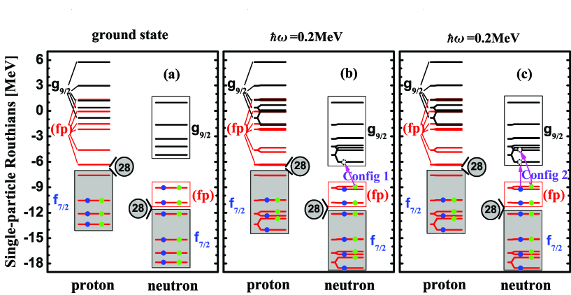
In the present TAC-CDFT calculation, as shown in Fig. 1(a), we first solve the Dirac equation for the ground state with MeV, by filling at each step of the iteration the proton and neutron levels according to their energy from the bottom of the well. As shown in Fig. 1(a), for the ground state, there are two paired proton holes sitting at the top of the shell, and four paired neutrons above the shell, and this configuration is associated with a triaxial deformation with and . Then, we start to rotate the nucleus, and thus the time-reversal symmetry is violated by the Coriolis term in the Dirac equation, which leads to an energy splitting of the time-reversal conjugate states with an amplitude up to 1.75 MeV at MeV. Note that a large splitting usually happens for states with a large expectation value which would induce strong Coriolis effects. At MeV, the ground-state configuration; i.e., , is still shown as being the yrast one. However, with increasing , the large energy splitting between the time-reversal conjugate states allows a one-particle-one-hole neutron excitation from the shell to the lowest orbital (), which leads to the configuration of ] (Config 1, see Fig. 1(b)). Similarly, the configuration is connected with a two-particle-two-hole neutron excitation from the shell to the two lowest orbitals () (Config 2, see Fig. 1(c)). In the following calculations with Config 1 or Config 2, the occupation of the valence nucleons is traced at different rotational frequencies by adopting the same prescription as in Ref. Peng et al. (2008).
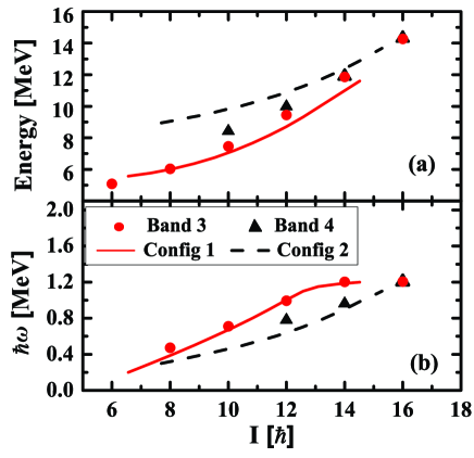
The calculated energy spectra and rotational frequency as functions of the total angular momentum are given in Fig. 2 in comparison with the data for the observed Bands 3 and 4 Steppenbeck et al. (2012) in 58Fe. In Fig. 2(a), one can clearly see that the excitation energies for Band 3 are reproduced well by the present TAC-CDFT calculation with Config 1. Moreover, the energies for the higher spin part of Band 4 are in good agreement of the calculated results for Config 2. Converged results were obtained up to around for Config 1, and around 15 for Config 2.
Fig. 2(b) indicates clearly that the angular momenta for Band 3 and Band 4 are reproduced well by the calculations with Config 1 and Config 2, respectively, and this indicates also that the present calculation is able to reproduce the moments of inertia rather well. For Band 3, in particular, the angular momentum increases almost linearly with the rotational frequency up to , while the observed unbending at may result from a level crossing between the proton and orbitals. In addition, it should be noted that the assigned configurations, Config 1 and Config 2, have negative and positive parity, respectively, and this is consistent with the previous investigation, based on the projected shell model Steppenbeck et al. (2012).
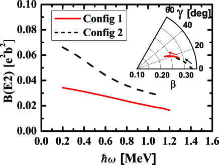
Typical characteristics of antimagnetic rotation include the absence of transitions and the decrease of the weak transitions with spin. In Fig. 3, the calculated reduced transition probabilities , for Config 1 and Config 2 are presented as functions of the rotational frequency. It is found that the calculated values here are very small (), and they exhibit a smooth decrease with the growth in spin. There are, at present, no available experimental values for these high-spin states in 58Fe. Further measurements are welcome to validate the predicted electromagnetic transition probabilities, and this would be very useful to understand the nature of these two bands. Furthermore, we note that the calculated values for both Config 1 and Config 2 vanish, and this is attributed to the fact that the transverse magnetic moments of two valence protons are anti-aligned and cancel out.
The decreasing tendencies of the values are connected with deformation changes. As shown in the inset of Fig. 3, with increasing rotational frequency, the nucleus undergoes a rapid decrease of deformation from 0.28 to 0.22 for Config 1, and from 0.34 to 0.26 for Config 2. Meanwhile, the values keep increasing from to for Config 1, and from nearly to for Config 2. Since considerable deformations are obtained here, it should be expected that collectivity plays a crucial role in the high-spin structure of these bands. Moreover, considering the fact that nuclear deformation here is changing toward stronger triaxiality with spin, this is even reminiscent of a “band terminating” picture that would apply to a normal collective band Wadsworth et al. (1998).
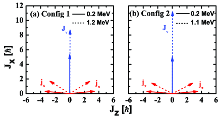
Therefore, it becomes important to check the mechanism behind the generation of the angular momentum in Bands 3 and 4. We present in Fig. 4 the angular momentum vectors for all neutrons and the two proton holes, in the shell, for Config 1 and Config 2, respectively. Here, the symbols have the same definition as in Refs. Zhao et al. (2011b, 2012). At the bandhead ( MeV), the two proton angular momentum vectors are pointing opposite to each other, and they are nearly perpendicular to the neutron angular momentum vector for both configurations. Together with , they form the blades of the two shears. With increasing rotational frequency, the gradual alignment of the vectors toward the vector generates partially the total angular momentum, and this corresponds to the so-called “two-shears-like mechanism”, where the two shears are closing simultaneously. On the other hand, it should be noted that the increase of the neutron angular momentum also contributes notably to the generation of the total angular momentum along the bands. In particular for the Config 2 band, the neutron angular momentum jumps by more than when the rotational frequency increases from 0.2 MeV to 1.1 MeV, while the alignment of the two proton holes only provides a contribution of less than . The increase of the neutron angular momentum results from the contribution of collective rotation. Thus, this is an instance where one can clearly see the interplay between the antimagnetic and collective rotation in the two configurations.
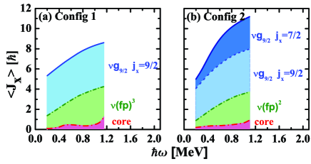
In a microscopic picture, the angular momentum comes from the individual nucleons self-consistently. Therefore, it is of interest to extract the contributions of the individual neutrons to the neutron angular momentum, and these are found in Fig. 5 for Config 1 and Config 2, respectively. One can see that the angular momentum contribution from the neutron core; i.e., from all the orbitals below , is quite small () for Config 1 and Config 2. However, the neutron angular momenta are almost all coming from the four valence neutrons in the and orbitals, which corresponds to a “band termination”.
For Config 1, a neutron sitting at the bottom of the shell contributes an angular momentum of roughly . When the rotational frequency increases from 0.3 MeV to 1.2 MeV, the contribution of this neutron does barely change, and the increment of the angular momentum comes mostly from the alignment of the other three neutrons in the shell, which is driven by the collectivity. In regards to the generation of the total angular momentum along the axis, the alignment of the neutron angular momentum contributes 3.35 (55%), while the two-shears-like mechanism contributes 2.74 (45%).
For Config 2, one additional valence neutron occupies the orbital. However, this neutron contributes almost nothing to the angular momentum at the bandhead, and this indicates that there is very strong mixing between this orbital and the low- orbits. Along the band, this orbital becomes purer and purer, and eventually provides roughly 3 to the total angular momentum. Therefore, such alignment originates from collective rotation as well, and together with the alignment of around 2.81, obtained from the two neutrons in the () shell, collective rotation then accounts for almost 73% to the increment of the total angular momentum.
Therefore, one can conclude that both the Config 1 and Config 2 bands correspond to rotating bands of the antimagnetic rotation character, but due to the substantial deformation, the interplay between antimagnetic rotation and collective motion plays an essential role. In particular for the Config 2 band, collective rotation is dominant in the competition with antimagnetic rotation. The higher angular momenta originate from the two-shears-like mechanism of antimagnetic rotation together with the alignment generated by the collective rotation.
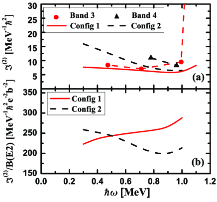
The complex interplay between the antimagnetic and collective rotations can be revealed by the dynamic moment of inertia and by the ratio. These are given in Fig. 6 as functions of the rotational frequency, in comparison with the data available Steppenbeck et al. (2012). The abrupt rise in the experimental dynamic moment of inertia of Band 3 ( MeV) corresponds to the unbending, and has been discussed in Fig. 2.
It is found that the moments of inertia for both Config 1 and Config 2 are reproduced reasonably, especially their evolution with frequency. For Config 1, the rise of the ratios is characteristic of antimagnetic rotation, reflecting the fact that is essentially constant whereas the values rapidly approach zero as the spin increases along the band (see Fig. 3). This is also consistent with the prediction of the classical model of Ref. Simons et al. (2005), where the behavior of and completely reflects how the interaction between the high- orbitals depends on their relative orientation. Note that for a pure antimagnetic rotor, the angular momentum is carried by only a few nucleons in high- orbitals.
For Config 2, however, the ratios exhibit decreasing tendency along the band, indicating that both and values drop with the reduction of deformation as the spin increases, and the former drop even faster than the latter. The rapid drop of () can be understood from the alignment of neutrons driven by the collective rotation, as seen in Fig. 5(b), the increment of which occurs gradually with increasing rotational frequency. It should be kept in mind that collective rotation is a motion carried by many nucleons, each of which contributes a small fraction to the total angular momentum. The averaging over the individual nucleon contributions results in both the and values being related to the deformation of the nuclear density distribution.
IV summary
In summary, the self-consistent tilted axis cranking covariant density functional theory based on a point-coupling interaction has been applied to investigate the possible existence of the antimagnetic rotation in the nucleus 58Fe. The energy spectra, the relation between the spin and the rotational frequency, the dynamic moment of inertia, the deformation parameters and the reduced transition probabilities have been studied. The energy spectra of Band 3 have been reproduced well with the configuration . The observed energies for the higher spin part of Band 4 are in good agreement with the calculated results for the configuration . The absence of measurable strength and the decreasing values for both Config 1 and Config 2 are consistent with the picture of a two-shears-like mechanism, which has been demonstrated by the orientation of the two-proton-hole and neutron angular momenta.
However, due to the presence of considerable deformation, collective rotation provides a significant contribution to the total angular momentum as well. In particular for the Config 2 band, collective rotation is dominant in the competition with antimagnetic rotation. In both bands, the interplay between antimagnetic rotation and collective motion plays an essential role, and it can be revealed by the behavior of their ratios with the spin.
Acknowledgements
The authors are grateful to R. V. F. Janssens and Robert B. Wiringa for helpful discussions and critical reading of the manuscript. This work is supported by the Major State 973 Program of China (Grant No. 2013CB834400), the National Natural Science Foundation of China (Grants No. 11175002, No. 11335002, No. 11461141002, No. 11105005), the Open Project Program of State Key Laboratory of Theoretical Physics, Institute of Theoretical Physics, Chinese Academy of Sciences, China (No.Y4KF041CJ1), and by U.S. Department of Energy (DOE), Office of Science, Office of Nuclear Physics, under contract DE-AC02-06CH11357.
References
- Bohr and Mottelson (1975) A. Bohr and B. R. Mottelson, NUCLEAR STRUCTURE Volume II: Nuclear Deformation (W. A. Benjamin, Inc., 1975).
- Frauendorf (2001) S. Frauendorf, Rev. Mod. Phys. 73, 463 (2001).
- Walker and Dracoulis (1999) P. Walker and G. Dracoulis, Nature 399, 35 (1999).
- Frauendorf and Meng (1997) S. Frauendorf and J. Meng, Nucl. Phys. A 617, 131 (1997).
- Frauendorf and Dönau (2014) S. Frauendorf and F. Dönau, Phys. Rev. C 89, 014322 (2014).
- Chen et al. (2014) Q. B. Chen, S. Q. Zhang, P. W. Zhao, and J. Meng, Phys. Rev. C 90, 044306 (2014).
- Matta et al. (2015) J. T. Matta, U. Garg, W. Li, S. Frauendorf, A. D. Ayangeakaa, D. Patel, K. W. Schlax, R. Palit, S. Saha, J. Sethi, T. Trivedi, S. S. Ghugre, R. Raut, A. K. Sinha, R. V. F. Janssens, S. Zhu, M. P. Carpenter, T. Lauritsen, D. Seweryniak, C. J. Chiara, F. G. Kondev, D. J. Hartley, C. M. Petrache, S. Mukhopadhyay, D. V. Lakshmi, M. K. Raju, P. V. Madhusudhana Rao, S. K. Tandel, S. Ray, and F. Dönau, Phys. Rev. Lett. 114, 082501 (2015).
- Frauendorf (1993) S. Frauendorf, Nucl. Phys. A 557, 259c (1993).
- Peng and Zhao (2015) J. Peng and P. W. Zhao, Phys. Rev. C 91, 044329 (2015).
- Clark and Macchiavelli (2000) R. M. Clark and A. O. Macchiavelli, Annu. Rev. Nucl. Part. Sci. 50, 1 (2000).
- Hübel (2005) H. Hübel, Prog. Part. Nucl. Phys. 54, 1 (2005).
- Meng et al. (2013) J. Meng, J. Peng, S. Q. Zhang, and P. W. Zhao, Front. Phys. 8, 55 (2013).
- Choudhury et al. (2010) D. Choudhury, A. K. Jain, M. Patial, N. Gupta, P. Arumugam, A. Dhal, R. K. Sinha, L. Chaturvedi, P. K. Joshi, T. Trivedi, R. Palit, S. Kumar, R. Garg, S. Mandal, D. Negi, G. Mohanto, S. Muralithar, R. P. Singh, N. Madhavan, R. K. Bhowmik, and S. C. Pancholi, Phys. Rev. C 82, 061308 (2010).
- Simons et al. (2003) A. J. Simons, R. Wadsworth, D. G. Jenkins, R. M. Clark, M. Cromaz, M. A. Deleplanque, R. M. Diamond, P. Fallon, G. J. Lane, I. Y. Lee, A. O. Macchiavelli, F. S. Stephens, C. E. Svensson, K. Vetter, D. Ward, and S. Frauendorf, Phys. Rev. Lett. 91, 162501 (2003).
- Choudhury et al. (2013) D. Choudhury, A. K. Jain, G. A. Kumar, S. Kumar, S. Singh, P. Singh, M. Sainath, T. Trivedi, J. Sethi, S. Saha, S. K. Jadav, B. S. Naidu, R. Palit, H. C. Jain, L. Chaturvedi, , and S. C. Pancholi, Phys. Rev. C 87, 034304 (2013).
- Simons et al. (2005) A. J. Simons, R. Wadsworth, D. G. Jenkins, R. M. Clark, M. Cromaz, M. A. Deleplanque, R. M. Diamond, P. Fallon, G. J. Lane, I. Y. Lee, A. O. Macchiavelli, F. S. Stephens, C. E. Svensson, K. Vetter, D. Ward, S. Frauendorf, and Y. Gu, Phys. Rev. C 72, 024318 (2005).
- Datta et al. (2005) P. Datta, S. Chattopadhyay, S. Bhattacharya, T. K. Ghosh, A. Goswami, S. Pal, M. S. Sarkar, H. C. Jain, P. K. Joshi, R. K. Bhowmik, R. Kumar, N. Madhavan, S. Muralithar, P. V. M. Rao, and R. P. Singh, Phys. Rev. C 71, 041305 (2005).
- Chiara et al. (2000) C. J. Chiara, S. J. Asztalos, B. Busse, R. M. Clark, M. Cromaz, M. A. Deleplanque, R. M. Diamond, P. Fallon, D. B. Fossan, D. G. Jenkins, S. Juutinen, N. S. Kelsall, R. Krücken, G. J. Lane, I. Y. Lee, A. O. Macchiavelli, R. W. MacLeod, G. Schmid, J. M. Sears, J. F. Smith, F. S. Stephens, K. Vetter, R. Wadsworth, and S. Frauendorf, Phys. Rev. C 61, 034318 (2000).
- Roy et al. (2011) S. Roy, S. Chattopadhyay, P. Datta, S. Pal, S. Bhattacharya, R. Bhowmik, A. Goswami, H. Jain, R. Kumar, S. Muralithar, D. Negi, R. Palit, and R. Singh, Phys. Lett. B 694, 322 (2011).
- Sugawara et al. (2012) M. Sugawara, T. Hayakawa, M. Oshima, Y. Toh, A. Osa, M. Matsuda, T. Shizuma, Y. Hatsukawa, H. Kusakari, T. Morikawa, Z. G. Gan, and T. Czosnyka, Phys. Rev. C 86, 034326 (2012).
- Sugawara et al. (2015) M. Sugawara, T. Hayakawa, M. Oshima, Y. Toh, A. Osa, M. Matsuda, T. Shizuma, Y. Hatsukawa, H. Kusakari, T. Morikawa, Z. G. Gan, and T. Czosnyka, Phys. Rev. C 92, 024309 (2015).
- Rather et al. (2014) N. Rather, S. Roy, P. Datta, S. Chattopadhyay, A. Goswami, S. Nag, R. Palit, S. Pal, S. Saha, J. Sethi, T. Trivedi, , and H. C. Jain, Phys. Rev. C 89, 061303(R) (2014).
- Rajbanshi et al. (2015) S. Rajbanshi, S. Roy, S. Nag, A. Bisoi, S. Saha, J. Sethi, T. Trivedi, T. Bhattacharjee, S. Bhattacharyya, S. Chattopadhyay, G. Gangopadhyay, G. Mukherjee, R. Palit, R. Raut, M. S. Sarkar, A. K. Singh, and A. Goswami, arXiv:nucl-th/1505.06074v1 (2015).
- Zhao et al. (2011a) P. W. Zhao, S. Q. Zhang, J. Peng, H. Z. Liang, P. Ring, and J. Meng, Phys. Lett. B 699, 181 (2011a).
- Zhao et al. (2011b) P. W. Zhao, J. Peng, H. Z. Liang, P. Ring, and J. Meng, Phys. Rev. Lett. 107, 122501 (2011b).
- Zhao et al. (2012) P. W. Zhao, J. Peng, H. Z. Liang, P. Ring, and J. Meng, Phys. Rev. C 85, 054310 (2012).
- Yu et al. (2012) L. F. Yu, P. W. Zhao, S. Q. Zhang, P. Ring, and J. Meng, Phys. Rev. C 85, 024318 (2012).
- Zhao et al. (2015a) P. W. Zhao, S. Q. Zhang, and J. Meng, arXiv:1506.08340 (2015a).
- Zhao et al. (2015b) P. W. Zhao, N. Itagaki, and J. Meng, Phys. Rev. Lett. 115, 022501 (2015b).
- Steppenbeck et al. (2012) D. Steppenbeck, R. V. F. Janssens, S. J. Freeman, M. P. Carpenter, P. Chowdhury, A. N. Deacon, M. Honma, H. Jin, T. Lauritsen, C. J. Lister, J. Meng, J. Peng, D. Seweryniak, J. F. Smith, Y. Sun, S. L. Tabor, B. J. Varley, Y.-C. Yang, S. Q. Zhang, P. W. Zhao, and S. Zhu, Phys. Rev. C 85, 044316 (2012).
- Zhao et al. (2010) P. W. Zhao, Z. P. Li, J. M. Yao, and J. Meng, Phys. Rev. C 82, 054319 (2010).
- Peng et al. (2008) J. Peng, J. Meng, P. Ring, and S. Q. Zhang, Phys. Rev. C 78, 024313 (2008).
- Wadsworth et al. (1998) R. Wadsworth, R. M. Clark, J. A. Cameron, D. B. Fossan, I. M. Hibbert, V. P. Janzen, R. Krücken, I. Y. M. A. O. Lane, G. J.and Lee, C. M. Parry, J. M. Sears, J. F. Smith, A. V. Afanasjev, and I. Ragnarsson, Phys. Rev. Lett. 80, 1174 (1998).