Periodic arrays of intercalated atoms in
twisted bilayer graphene:
an ab initio investigation
Abstract
We have performed an ab initio investigation of transition metals (TMs = Mo, Ru, Co, and Pt) embedded in twisted bilayer graphene (tBG) layers. Our total energy results reveal that, triggered by the misalignment between the graphene layers, Mo and Ru atoms may form a quasi-periodic (triangular) array of intercalated atoms. In contrast, the formation of those structures is not expected for the other TMs, Co and Pt atoms. The net magnetic moment (m) of Mo and Ru atoms may be quenched upon intercalation, depending on the stacking region (AA or AB). For instance, we find a magnetic moment of 0.3 (1.8 ) for Ru atoms intercalated between the AA (AB) regions of the stacked twisted layers. Through simulated scanning tunneling microscopy (STM) images, we verify that the presence of intercalated TMs can be identified by the formation of bright (hexagonal) spots lying on the graphene surface.
I Introduction
The synthesis of graphene and the experimental measurements of its outstanding properties Novoselov et al. (2005) opened a pathway to explore and synthesize other single layer or few layers two dimensional (2D) materials such as hexagonal boron nitride (hBN), molybdenum disulphide Wang et al. (2012); Mak et al. (2010) and phosphorene, a single layer of black phosphorus Castellanos-Gomez et al. (2014). Furthermore the concept of van der Waals (vdW) heterostructure has emerged Geim and Grigorieva (2013), layers of 2D materials, which interact by means of vdW forces, are piled up, aiming to provide a suitable set of electronic and structural properties. Recently heterostructures conformed by vertically stacked layers of graphene/hBN/graphene have been successfully synthesized Mishchenko et al. (2014), in these cases the different lattice constants and/or a relative rotation angle (RRA) between layer lead to moiré patterns that are observed in scanning tunneling microscopy (STM) images.
The synthesis of few layer graphene by chemical methodsVarchon et al. (2008a); Reina et al. (2009), for instance, shows quite often a rotation between graphene layers with respect to the Bernal or AB stacking. This gives rise to a moiré pattern with a periodicity that can be associated with the RRA between layers. This structure is known as twisted bilayer graphene (tBG) and it has been extensively studied due to its peculiar electronic propertiesLopes dos Santos et al. (2007); Varchon et al. (2008b); Du et al. (2009); Trambly de Laissardière et al. (2010); Shallcross et al. (2010); Suárez Morell et al. (2010); Havener et al. (2012); Lu et al. (2013); Suárez Morell et al. (2013); Shallcross et al. (2013); Zhang and Luo (2014); Chung et al. (2015).
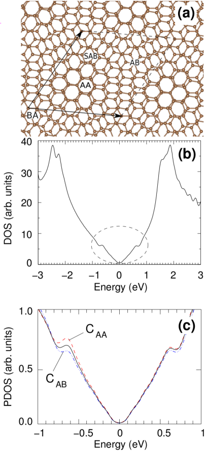
In tBG, there is a so-called AA region where the stacking is similar to AA bilayer graphene, with one atom exactly above another atom of the other layer, and another region with AB stacking, the AB region. Between the AA and AB regions the stacking looks like two random slipped layers. The size of the tBG unit cell (UC) and of the AA region is increased for low RRA and the system can be thought as a large AA region surrounded by AB areas, as depicted in Fig. 1(a). Low energy electrons are localized in the AA region as they can not easily penetrate the barrier formed by the AB stackingLuican et al. (2011); Trambly de Laissardière et al. (2012); Lopes dos Santos et al. (2012). The local density of states is significantly larger at the AA site for very low angles and this is precisely the region one observe in STM imagesVarchon et al. (2008b); Miller et al. (2010); Ohta et al. (2012). The electronic spectrum also depends on the RRA. For large RRA (), the system behaves as if the two layers were uncoupled with a linear energy dispersion like in monolayer graphene. Below there is a constant reduction of the Fermi velocity of charge carriers and close to the spectrum shows zero-velocity flat bands. Scanning tunneling spectroscopy (STS) measurements have shown angle dependent Van Hove singularities(vHs) near the fermi levelDu et al. (2009) consistent with the behavior predicted by theoretical methodsLopes dos Santos et al. (2007); Varchon et al. (2008b); Trambly de Laissardière et al. (2010); Shallcross et al. (2010); Suárez Morell et al. (2010).
There have been recently several proposals to exploit the properties of graphene by intercalation of metals. An enhancement of the out of plane magnetic anisotropy have been observed in intercalated Cobalt atoms between graphene and Ir(111) substrate Decker et al. (2013); Vlaic et al. (2014), the anisotropy also depends on the specific site of the unit cell where the Co atoms are deposited Decker et al. (2013). In some cases the intercalated Co atoms forms a quasi-periodic array of trimers between graphene adlayer and the SiC(0001) surface de Lima et al. (2014). Besides, the geometry of adatoms adsorbed on the graphene surface, might play a very important role on the formation of quantum spin and anomalous Hall phases in graphene Acosta et al. (2014).
In this work we propose to take advantage of the moiré structure in twisted bilayer graphene to create a periodic array of intercalated transition metal(TM) atoms. If there is any energetic preference for the atoms to be localized in a given region between the layers of the twisted unit cell it might be possible to control the distance between them by manipulating the RRA between layers, allowing or not the interaction between atoms and controlling the electronic/magnetic properties of the system.
We examine, based on ab initio total energy calculations, the energetic stability and the electronic properties of TMs (TM=Mo, Ru, Co, and Pt) intercalated between tBG layers. We found that Mo and Ru atoms exhibit an energetic preference for the AA stacking region (TMAA) of the twisted bilayer unit cell, while no such a preference is found for Co and Pt. This suggest that Mo and Ru intercalated atoms might form a quasi-periodic triangular array embedded in the twisted layers. At the same time the net magnetic moment of Mo, Ru and Co atoms are somewhat quenched upon their intercalation, for instance, we found a magnetic moment of 0.3 for Ru adatoms intercalated in the AA stacking region. Through STM simulation, we show that there is an increase of the electronic density of states on the (graphene) C atoms bonded to the TM incorporation sites.
II Method
II.1 Geometry of the Unit cell.
The system we studied is composed of two coupled graphene layers with a given RRA between them. We built a commensurate unit cell following a procedure exposed in several previous worksCampanera et al. (2007); Suárez Morell et al. (2011). Starting from a stacked AB bilayer graphene one rotate a lattice point to an equivalent location, a vector is rotated to , where and are the graphene bilayer lattice vectors; n,m are integers. These integers are the only information needed to completely characterize the unit cell, the rotating angle, the unit cell vectors, and the numbers of atoms in the UC can be expressed in terms of themSuárez Morell et al. (2010); Lopes dos Santos et al. (2012). The UC constructed this way contains one site, known as AA, where one atom is exactly above another atom of the other layer, there is another site, AB, where an atom of the top layer is exactly in the center of a lower layer hexagon, we have also a BA site, equivalent to the AB site but with the difference that an atom in the lower layer is in the center of an hexagon of the upper layer, there is also another area of the UC where the stacking is none of the above mentioned we call it slipped AB (SAB), see Fig. 1(a). As the UC gets larger, very small RRA, the number of atoms with almost exact AA or AB character increasesCampanera et al. (2007) creating large regions with almost the same stacking. The distance between two AA regions (periodicity of the superlattice) can be calculated by the equation , where Å and is the RRA between layers.
II.2 DFT calculations
The calculations were performed within the density functional theory (DFT) approach, as implemented in the Quantum-Espresso package Giannozzi et al. (2009). The Kohn-Sham orbitals were expanded in a plane-wave basis set, with an energy cutoff of 35 Ry. The twisted graphene bilayers were simulated considering supercells with 148 (tGB-148) and 244 (tGB-244) atoms, corresponding to RRA () of and , respectively, and vacuum regions of 14 Å. calculations. The atomic positions were fully relaxed, by including van der Waals (vdW) interactions within the self-consistent vdW-DF approach as described in Refs. Dion et al. (2004); Thonhauser et al. (2007); Roman-Perez and Soler (2009). For the structural relaxations we have considered a force convergence tolerance of 15 meV/Å and the Brillouin zone (BZ) was sampled by () k-points in the case of tGB-148 (tGB-244). After the structural relaxations, spin polarized calculations were performed with () k-points BZ sampling in the case of tGB-148 (tGB-244).
III Results
We begin examining the electronic and structural properties of the twisted bilayer graphene crystal in comparison with recent experimental and theoretical findings. In Fig. 1(a) we show the structural model of tGB-148, indicating the AA and AB stacking regions. At equilibrium, the averaged interlayer distance () is 3.679 Å; slightly larger than the distance obtained for perfect bilayer graphene (AB or Bernal stacking). There are no chemical bonds between the graphene sheets, the interlayer interaction is governed by vdW forces, we found a binding energy of 27 meV/C-atom very close to the experimental value of graphiteBenedict et al. (1998); Liu et al. (2012). In the case of tGB-148, RRA = , a slight renormalization of the Fermi velocity and the presence of vHs, associated with the M point of the BZ are expectedSuárez Morell et al. (2010). The energy of these vHs depends on the RRA, diminishing as the angle gets lower Du et al. (2009); Luican et al. (2011); Brihuega et al. (2012). We found that the vHs lie at eV with respect to the Dirac point, as shown in Fig. 1(b) in agreement with previous experimental resultsBrihuega et al. (2012).
The moiré structure gives rise to a periodic potential that have a huge impact on the electronic dispersion and at the same time promotes a charge density redistribution confining low energy electrons to the AA region, producing the bright spot observed in STM experiments on graphite or tBG Varchon et al. (2008b); Miller et al. (2010); Ohta et al. (2012).
The origin of these bright spots were the subject of a debate not so long agoPong and Durkan (2005). Two theories were vindicated: (i) there is an increase of the electronic density of states around the AA region, when compared with the AB area and (ii) the AA and AB regions present different equilibrium geometries, and the interlayer distances (topographic corrugation) are different. Both arguments are valid and indeed, (i) can be verified in Fig. 1(c), by projecting the electronic DOS on the C atoms near the AA (CAA) and AB (CAB) stacking regions. The electronic density of states is larger on CAA. In addition, comparing the equilibrium geometries, we find that the interlayer distance in the AA region ( Å) is larger by 0.04 Å than in the AB one ( Å), as proposed in (ii). By reducing the twist-angle to 7.34∘ (tGB-244), the lateral distance between the AA and AB regions increases, when compared with tGB-148, and we find practically the same (averaged) interlayer distance, 3.681 Å. However, the interlayer distance in AA region increases to Å, while in the AB region we find practically the same distance ( Å). These small changes in the interlayer distances suggest that the origin of the STM images is mainly electronic rather than geometricalCisternas and Correa (2012).
We found pertinent to investigate whether this behavior facilitates the creation of periodic arrays of intercalated atoms between twisted graphene layers. To such end we studied the energetic stability of transition metal atoms (TMs: Mo, Ru, Co, and Pt) intercalated at different sites of the tBG unit cell. A measure of the energetic stability is the binding energy of the TMs embedded in the twisted systems, the binding energy () can be obtained from:
Where is the total energy of the final system, a tBG intercalated by a TM atom. and are the total energies of the separated components, a tBG and an isolated TM atom, respectively.
We calculated the binding energy at several locations within the UC and found that for Co and Pt the differences are small, there is not any clear preference for any region. However for Mo and Ru the difference can be as large as 1 eV, and the highest binding energy is obtained in the AA region and the lowest in the AB one. In the rest of the UC the results are in between these two extreme values.
In addition we have calculated the binding energy but with the TM atoms adsorbed on the surface site(an atom on top of the upper layer). We obtained, for the tBG-148 structure, of 3.48, and 2.47 for Mo and Ru adatoms lying on the hollow site of the AA region, and 1.44 eV for Pt adatom on the bridge site. These values are significantly smaller than the ones obtained for the intercalated atoms.
| (tBG-148) | (tBG-244) | |||
|---|---|---|---|---|
| TM | AA | AB | AA | AB |
| Mo | 5.79 | 4.64 | 5.88 | 4.73 |
| Ru | 3.76 | 3.16 | 3.80 | 3.20 |
| Co | 2.74 | 2.73 | 2.74 | 2.73 |
| Pt | 1.66 | 1.63 | 1.77 | 1.71 |
Table I shows the values of the binding energy for the AA and AB regions for all the intercalated TM considered. There is an energetic preference (higher binding energies) for Ru and Mo atoms intercalated in the AA region. For the tBG-148 system, the MoAA(RuAA) structure is more stable than MoAB(RuAB) by 1.15 eV (0.60 eV). Such energetic preference has been maintained in tBG-244. That is, the binding energies of MoAA and RuAA are higher by 1.15 and 0.60 eV, respectively, compared with the ones of MoAB and RuAB. On the other hand, the energetic preference for the AA stacking region reduces to 0.03 eV (0.06 eV) for PtAA/tBG-148 (PtAA/tBG-244), while the CoAA and CoAB systems present practically the same binding energy. In the appendix we show the results of the binding energies for Ru and Mo in other regions of the UC. In general within the AA region the differences are small (around 1%) and in the SAB and AB regions the binding energies are around 5% and 20 % lower, respectively, than in the AA region.
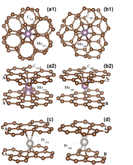
In Figs. 2(a) and 2(b) we show the structural models of Mo atoms intercalated in the regions AA and AB, the structural models of Ru and Co are very similar. In the AA stacking region the TM atom lies on the center of one of the empty hexagons (Fig. 2(a)), in this case the TM atom is bonded to 12 carbon atomscoo . On the other hand, in the AB stacking region (Fig. 2(b)), the TM atom lies on top of one atom of one layer, and on the hollow site of the other one. In this case, the coordination of the TM atom is reduced to seven. The interlayer distance, upon the presence of intercalated Mo and Ru atoms, Å, is slightly larger compared with the one obtained for the pristine twisted system. Whereas, we find around 3.85 Å for MoAB and RuAB, thus suggesting that those structures induce a larger local strain when compared with their MoAA and RuAA counterparts. Differently from the other TM atoms, the Pt atoms lie on the bridge site of the graphene layer in both stacking regions, Figs.2(c) and 2(d). Thus in both cases Pt atoms are bonded to four carbon atoms. Mo and Ru atoms, as d-orbital metals, tend to have as many bonds as possible when they are in contact with organic materials while Pt atoms behave more like noble elements.
For Co atoms the different coordination in the AA and AB stacking region do not lead to large differences in the total energies. This is due to the fact that Co covalent radius is smaller than Mo and Ru radius, thus it is expected because the covalent bonds between Co and carbon atoms are not as strong as Mo(Ru)-C bonds.
We proceed now to quantify the local strain in the twisted graphene bilayer, upon the intercalation of the TM atoms, we calculate the deformation energy (),
here and represent the total energies of pristine (full relaxed) and strained tBG-148 system, respectively. The latter term was obtained by considering the atomic positions of the deformed (due to the presence of the intercalated TM) tBG-148 structure. The deformation energies for Mo and Ru atoms intercalated in the AA stacking region MoAA and RuAA are 0.12 and 0.09 eV respectively, while it increases by about 0.1 eV (= 0.24 (0.19) eV) for MoAB (RuAB). That is, the local strain also contributes to the energetic preference for the AA stacking regions for these two transition metals. On the other hand, for intercalated Co and Pt atoms, the differences are smaller, 0.024 and 0.015 eV, respectively.
Summarizing the total energy results; we have found that the most stable place for Mo and Ru atoms, intercalated in tBG, is in the AA stacking region. This total energy difference may be explained by the different chemical coordination and also by the strain energy differences.
Therefore our results indicate that Mo and Ru atoms may form a quasi-periodic triangular array when they are intercalated in twisted graphene layers, the most stable position is within the AA region and the energy differences with other regions are larger than room temperature thermal energy. The periodicity of these arrays can be tuned by the twist angle.
The relative charge concentration around the AA region increases as the angle gets lower we expect then that the binding energy at the AA region will be larger when we compare with the rest of the UC for lower angles as the charge density should be proportional to the strength of the covalent bond between TM and Carbon.
We will focus now on the electronic and magnetic properties of intercalated TM atoms. Mo and Ru have different magnetic moments (m) when we compare with the adsorbed ones, as can be noticed in Table II. The magnetic moment of Mo is quenched when it is intercalated in both AA and AB stacking regions. Ru magnetic moment is also quenched in the more energetically stable AA stacking region but not in the AB region. Those changes on the magnetic moment are ruled by the different TM hybridization with the tBG host. The magnetic moments of Co is almost unchanged when comparing adsorbed and intercalated results. This is another evidence for the fact, mentioned above, that Co-carbon bonds are weaker in comparison with Mo-carbon and Ru-carbon bonds.
| TM | mads | mAA | mAB |
|---|---|---|---|
| Mo | 2.0 | 0.1 | 0.0 |
| Ru | 1.9 | 0.3 | 1.8 |
| Co | 1.2 | 1.4 | 1.2 |
| Pt | 0.0 | 0.0 | 0.0 |
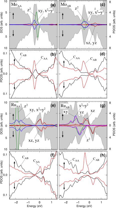
There is an electronic charge transfer from the Mo and Ru atoms in the AA region to the graphene layers. This lead to n-type doped tBG, with charge transfers of 3.2 and , for Mo and Ru atoms, respectively. Also, the local hybridization of TMs in AA and AB regions are different, as shown by the calculated spin-polarized electronic density of states (DOS), shaded plots in Fig. 3, and projected DOS (PDOS, solid lines in Fig. 3). The Mo-4d electronic states are mostly localized below the Fermi level ( eV), and the net magnetic moment of 0.1 comes from a small occupation unbalance of Mo-4d orbitals, indicated by green solid line in Fig. 3(a). It is worth noting that although the symmetry of the intercalated MoAA atom is slightly missed, due to the twist angle, the double degeneracy of 4dxy/4d and 4dxz/4dyz (levels and ) have been preserved. In addition, as presented in Fig. 3(b), there is an increase of the DOS projected on the C atoms bonded to MoAA, CAA in Fig. 2(a2).
The hybridization of Mo atoms in the AB region with the graphene layers has been strengthened due to the formation of Mo-C bond with a C atom of the graphene layer B [Fig. 2(b2)]. In this case, the occupation of Mo-4d reduces by around 20%, followed by an increase of the PDOS on the C atoms bonded to MoAB (CAB), Figs. 3(c) and 3(d).
In Figs. 3(e) and 3(f) we present the DOS and PDOS of RuAA/tBG-148. Here, the double degeneracy of the levels and , composed by Ru-4dxy/4d and Ru-4dxz/4dyz have been maintained [Fig. 3(e)], while the Ru-4d (lying at eV) weakly interact with the tBG-148 host. The net magnetic moment of 0.3 comes from the partial occupation unbalance of Ru-4dxz and 4dyz orbitals, as well as from the 2pz orbitals of CAA atoms, Fig. 3(f). Similarly to the MoAB/tBG, the localized character of RuAA-4d orbitals has been missed in RuAB/tBG, Fig. 3(g). In addition, we find that spin-down states, composed by Ru-4dxz and -4dyz orbitals, becomes unoccupied increasing the net magnetic moment to 1.8 . The electronic DOS of the carbon atoms bonded to RuAB, CAB, increases compared with the other C atoms of the graphene layer [Fig. 3(h)]; contributing to the net magnetic moment of RuAB/tBG.
The changes in the electronic density of states on the graphene sheet, induced by the intercalated TMs, can be visualized through STM images. Here, based on Tersoff-Hamman Tersoff and Hamann (1985) approach, we simulate a STM image of occupied states, within eV, of MoAA/ and RuAA/tBG-148. As depicted in Figs. 4(a) and 4(b), we find bright hexagonal spots lying on the C atoms above the intercalated MoAA and RuAA atoms, respectively. Those spots form a triangular array, and the brightness can be assigned to the larger PDOS of CAA atoms [Figs. 3(b) and 3(f)]. In addition to the electronic contribution, the graphene surface corrugation may play an important role. As discussed above, the interlayer distance increases slightly upon the presence of intercalated TMs, e.g. Å for Mo and Ru in the AA stacking region.
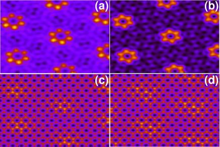
In order to verify the importance of such a corrugation on the STM images, we simulated STM images of the twisted graphene (tBG-148) by removing the intercalated atoms; but keeping the equilibrium geometry of the MoAA/ and RuAA/tBG-148 systems. Our simulated STM results presented in Figs. 4(c) and 4(d) show that indeed the bright spots follow the topographic corrugation of the graphene surface.
Several studies have been addressed to the formation of magnetic clusters at the graphene/surface interface Vo-Van et al. (2011); Decker et al. (2013, 2014); Vlaic et al. (2014); de Lima et al. (2014). In those systems, the formation of (self-assembled) periodic structures is ruled by a suitable synergy between the hexagonal lattice of the graphene layer, and the atomic geometry of the surface. Our results suggest that the array of Mo and Ru atoms intercalated in the twisted graphene layers can act as a seed to the formation of these type of clusters. Indeed, our preliminary results indicate that the formation of Ru-dimers intercalated in the AA stacking region is quite likely. For Ru-dimers we find of 4.00 eV/atom, whereas for Ru-trimers we obtained 4.05 eV/atom. Further studies regarding the formation of TM clusters in twisted graphene layers are in progress.
IV Summary
We have performed an ab initio investigation of TM atoms (Mo, Ru, Co and Pt) intercalated in twisted graphene layers. Our results show that Mo and Ru are significantly more stable energetically at tBG AA stacking region in comparison with the rest of the unit cell. For Co and Pt atoms the energy differences between regions are not relevant. These results indicate that it is possible a formation of a triangular array of Mo and Ru atoms, ruled by the twist angle between the graphene layers. In contrast, formation of such a structure is not expected for Co and Pt atoms. The energetic stability of Mo and Ru atoms at tBG AA stacking regions can be explained in terms of the coordination number of the TM atoms with carbon atoms and also differences in strain energy. The net magnetic moments of Mo is quenched upon its intercalation in AA or AB regions, while Ru magnetic moment is 1.9 in the adsorbed system and goes to 0.3 when intercalated in the AA region. There is an increase of the electronic density of states, near the Fermi level, on the graphene carbon atoms bonded to the TM atoms, identified through STM images. We find the formation of a triangular array of hexagonal bright spots lying on the C atoms nearest neighbour to the intercalated Mo and Ru atoms. These spots in the STM images may be used to experimentally identify the intercalated atoms positions.
The authors acknowledge financial support from the Brazilian agencies CNPq, CAPES and FAPEMIG, the computational support from CENAPAD/SP and Chilean FONDECYT grant 1130950.
V Appendix
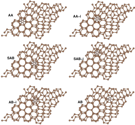
In Fig. 5 we show other positions of the intercalated TM atoms inside the tBG unit cell(tGB-148). The results are for Ru and Mo intercalated atoms since these are the systems with large energy differences between AA and AB regions. In these cases in order to preserve the RRA unchanged during the atomic relaxation process, the C atoms of graphene layers are allowed to relax only along the z-direction; such a constrain is not applied to the intercalated TMs. In Table 3 we present the total energy differences () with respect to the energetically more stable TMAA position,
where represents the total energy when the TM is located at the AA region, and is the total energy of the other locations (X = AA-i, SAB, SAB-i, AB, and AB) depicted in Fig. 5. These results indicate that indeed, there is an energetic preference for the AA sites. The total energy difference () increases from TMAA to TMAB. The results of Tables I and III lead us to conclude that the in plane relaxation ( and direction) plays a minor role on the energetic preference of TM atoms. In Table I, where in plane relaxation is considered, the results are very close to the ones obtained in Table III where it has not been allowed.
| TMX | Ru | Mo |
|---|---|---|
| TMAA | 0.000 | 0.000 |
| TMAA-i | 0.085 | 0.120 |
| TMSAB | 0.168 | 0.249 |
| TMSAB-i | 0.290 | 0.541 |
| TMAB-i | 0.296 | 0.478 |
| TMAB | 0.583 | 1.185 |
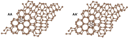
In addition, we compare the total energies for Ru/ and Mo/tGB-148 embedded in AA-like regions, indicated as AA and AA′ in Fig. 6. The atomic positions of the TM and tGB are free to relax. Those AA and AA′ configuration are very close in energy; we find differences of 0.007 and 0.024 eV.
References
- Novoselov et al. (2005) K. S. Novoselov, A. K. Geim, S. V. Morozov, D. Jiang, M. I. Katsnelson, V. Grigoreva, S. V. Dubonos, and A. A. Firsov, Nature 438, 197 (2005).
- Wang et al. (2012) Q. H. Wang, K. Kalantar-Zadeh, A. Kis, J. N. Coleman, and M. S. Strano, Nat Nano 7, 699 (2012).
- Mak et al. (2010) K. F. Mak, C. Lee, J. Hone, J. Shan, and T. F. Heinz, Phys. Rev. Lett. 105, 136805 (2010).
- Castellanos-Gomez et al. (2014) A. Castellanos-Gomez, L. Vicarelli, E. Prada, J. O. Island, K. L. Narasimha-Acharya, S. I. Blanter, D. J. Groenendijk, M. Buscema, G. A. Steele, J. V. Alvarez, H. W. Zandbergen, J. J. Palacios, and H. S. J. van der Zant, 2D Materials 1, 025001 (2014).
- Geim and Grigorieva (2013) A. K. Geim and I. V. Grigorieva, Nature 499, 419 (2013).
- Mishchenko et al. (2014) A. Mishchenko, J. S. Tu, Y. Cao, R. V. Gorbachev, J. R. Wallbank, M. T. Greenaway, V. E. Morozov, S. V. Morozov, M. J. Zhu, S. L. Wong, F. Withers, C. R. Woods, Y.-J. Kim, K. Watanabe, T. Taniguchi, E. E. Vdovin, O. Makarovsky, T. M. Fromhold, V. I. Fal’ko, A. K. Geim, L. Eaves, and K. S. Novoselov, Nature Nanotechnology 9, 808 (2014).
- Varchon et al. (2008a) F. Varchon, P. Mallet, L. Magaud, and J.-Y. Veuillen, Phys. Rev. B 77, 165415 (2008a).
- Reina et al. (2009) A. Reina, X. Jia, J. Ho, D. Nezich, H. Son, V. Bulovic, M. S. Dresselhaus, and J. Kong, Nano Letters 9, 30 (2009).
- Lopes dos Santos et al. (2007) J. M. B. Lopes dos Santos, N. M. R. Peres, and A. H. Castro Neto, Phys. Rev. Lett. 99, 256802 (2007).
- Varchon et al. (2008b) F. Varchon, P. Mallet, L. Magaud, and J.-Y. Veuillen, Phys. Rev. B 77, 165415 (2008b).
- Du et al. (2009) X. Du, I. Skachko1, F. Duerr, A. Luican, and E. Y. Andrei, Nature 462, 192 (2009).
- Trambly de Laissardière et al. (2010) G. Trambly de Laissardière, D. Mayou, and L. Magaud, Nano Letters 10, 804 (2010).
- Shallcross et al. (2010) S. Shallcross, S. Sharma, E. Kandelaki, and O. A. Pankratov, Phys. Rev. B 81, 165105 (2010).
- Suárez Morell et al. (2010) E. Suárez Morell, J. D. Correa, P. Vargas, M. Pacheco, and Z. Barticevic, Phys. Rev. B 82, 121407 (2010).
- Havener et al. (2012) R. W. Havener, H. Zhuang, L. Brown, R. G. Hennig, and J. Park, Nano Letters 12, 3162 (2012), pMID: 22612855.
- Lu et al. (2013) C.-C. Lu, Y.-C. Lin, Z. Liu, C.-H. Yeh, K. Suenaga, and P.-W. Chiu, ACS Nano 7, 2587 (2013), pMID: 23448165.
- Suárez Morell et al. (2013) E. Suárez Morell, M. Pacheco, L. Chico, and L. Brey, Phys. Rev. B 87, 125414 (2013).
- Shallcross et al. (2013) S. Shallcross, S. Sharma, and O. Pankratov, Phys. Rev. B 87, 245403 (2013).
- Zhang and Luo (2014) X. Zhang and H. Luo, The Journal of Physical Chemistry C 118, 20461 (2014).
- Chung et al. (2015) T.-F. Chung, R. He, T.-L. Wu, and Y. P. Chen, Nano Letters 15, 1203 (2015), pMID: 25621859.
- Luican et al. (2011) A. Luican, G. Li, A. Reina, J. Kong, R. R. Nair, K. S. Novoselov, A. K. Geim, and E. Y. Andrei, Phys. Rev. Lett. 106, 126802 (2011).
- Trambly de Laissardière et al. (2012) G. Trambly de Laissardière, D. Mayou, and L. Magaud, Phys. Rev. B 86, 125413 (2012).
- Lopes dos Santos et al. (2012) J. M. B. Lopes dos Santos, N. M. R. Peres, and A. H. Castro Neto, Phys. Rev. B 86, 155449 (2012).
- Miller et al. (2010) D. L. Miller, K. D. Kubista, G. M. Rutter, M. Ruan, W. A. de Heer, P. N. First, and J. A. Stroscio, Phys. Rev. B 81, 125427 (2010).
- Ohta et al. (2012) T. Ohta, J. T. Robinson, P. J. Feibelman, A. Bostwick, E. Rotenberg, and T. E. Beechem, Phys. Rev. Lett. 109, 186807 (2012).
- Decker et al. (2013) R. Decker, J. Brede, N. Atodiresei, V. Caciuc, S. Blgel, and R. Wiesendanger, Phys. Rev. B 87, 041403(R) (2013).
- Vlaic et al. (2014) S. Vlaic, A. Kimouche, J. Coraux, B. Santos, A. Locatelli, and N. Rougemaille, Appl. Phys. Lett. 104, 101602 (2014).
- de Lima et al. (2014) L. H. de Lima, R. Landers, and A. de Siervo, Chemistry of Materials 26, 4172 (2014).
- Acosta et al. (2014) C. M. Acosta, M. P. Lima, R. H. Miwa, A. J. R. da Silva, and A. Fazzio, Phys. Rev. B 89, 155438 (2014).
- Campanera et al. (2007) J. M. Campanera, G. Savini, I. Suarez-Martinez, and M. I. Heggie, Phys. Rev. B 75, 235449 (2007).
- Suárez Morell et al. (2011) E. Suárez Morell, P. Vargas, L. Chico, and L. Brey, Phys. Rev. B 84, 195421 (2011).
- Giannozzi et al. (2009) P. Giannozzi et al., J. Phys.: Condens. Matter 21, 395502 (2009).
- Dion et al. (2004) M. Dion, H. Rydberg, E. Schrder, D. C. Langreth, , and B. I. Lundqvist, Phys. Rev. Lett. 92, 246401 (2004).
- Thonhauser et al. (2007) T. Thonhauser, V. R. Cooper, S. Li, A. Puzder, P. Hyldgaard, and D. C. Langreth, Phys. Rev. B 76, 125112 (2007).
- Roman-Perez and Soler (2009) G. Roman-Perez and J. M. Soler, Phys. Rev. Lett. 103, 096102 (2009).
- Benedict et al. (1998) L. X. Benedict, N. G. Chopra, M. L. Cohen, A. Zettl, S. G. Louie, and V. H. Crespi, Chemical Physics Letters 286, 490 (1998).
- Liu et al. (2012) Z. Liu, J. Z. Liu, Y. Cheng, Z. Li, L. Wang, and Q. Zheng, Phys. Rev. B 85, 205418 (2012).
- Brihuega et al. (2012) I. Brihuega, P. Mallet, H. González-Herrero, G. Trambly de Laissardière, M. M. Ugeda, L. Magaud, J. M. Gómez-Rodríguez, F. Ynduráin, and J.-Y. Veuillen, Phys. Rev. Lett. 109, 196802 (2012).
- Pong and Durkan (2005) W.-T. Pong and C. Durkan, Journal of Physics D: Applied Physics 38, R329 (2005).
- Cisternas and Correa (2012) E. Cisternas and J. Correa, Chemical Physics 409, 74 (2012).
- (41) We consider that a TM atom is bonded to a carbon atom when the distance between then is smaller or equal to 2.5 Å.
- Tersoff and Hamann (1985) J. Tersoff and D. R. Hamann, Phys. Rev. B 31, 805 (1985).
- Vo-Van et al. (2011) C. Vo-Van, S. Schumacher, J. Coraux, V. Sessi, O. Fruchart, N. B. Brookes, P. Ohresser, and T. Michely, Appl. Phys. Lett. 99, 142504 (2011).
- Decker et al. (2014) R. Decker, M. Bazarnik, N. Atodiresei, V. Caciuc, S. Blgel, and R. Wiesendanger, J. Phys. Condens. Matter 26, 394004 (2014).