Multi-Element Logic Gates for Trapped-Ion Qubits
Precision control over hybrid physical systems at the quantum level is important for the realization of many quantum-based technologies. In the field of quantum information processing (QIP) and quantum networking, various proposals discuss the possibility of hybrid architectures Wallquist2009 where specific tasks are delegated to the most suitable subsystem. For example, in quantum networks, it may be advantageous to transfer information from a subsystem that has good memory properties to another subsystem that is more efficient at transporting information between nodes in the network. For trapped-ions, a hybrid system formed of different species introduces extra degrees of freedom that can be exploited to expand and refine the control of the system. Ions of different elements have previously been used in QIP experiments for sympathetic cooling Barrett2003 , creation of entanglement through dissipation Lin2013 , and quantum non-demolition (QND) measurement of one species with another Hume2007 . Here, we demonstrate an entangling quantum gate between ions of different elements which can serve as an important building block of QIP, quantum networking, precision spectroscopy, metrology, and quantum simulation. A geometric phase gate between a 9Be+ ion and a 25Mg+ ion is realized through an effective spin-spin interaction generated by state-dependent forces induced with laser beams Sorenson99 ; Sorenson2000 ; Milburn1999 ; Solano1999 ; Leibfried2003 . Combined with single-qubit gates and same-species entangling gates, this mixed-element entangling gate provides a complete set of gates over such a hybrid system for universal QIP Barenco1995 ; Bremner2002 ; Zhang2003 . Using a sequence of such gates, we demonstrate a Controlled-NOT (CNOT) gate and a SWAP gate NielsonChuang . We further demonstrate the robustness of these gates against thermal excitation and show improved detection in quantum logic spectroscopy (QLS) Schmidt2005 . We also observe a strong violation of a CHSH-type Bell inequality CHSH1969 on entangled states composed of different ion species.
Trapped ions of different elements vary in mass, internal atomic structure and spectral properties, features that can make certain species suited for particular tasks such as storing quantum information, high fidelity readout, fast logic gates, or interfacing between local processors and photon interconnects. One important advantage of a hybrid system incorporating trapped ions of different elements is the ability to manipulate and measure one type of qubit using laser beams with negligible effects on the other since the resonant transition wavelengths differ substantially. When scaling trapped-ion systems to greater numbers and density of ions, it will be advantageous to perform fluorescence detection on individual qubits without inducing decoherence on neighboring qubits due to uncontrolled photon scattering. To provide this function in a hybrid system one can use an entangling gate to transfer the qubit states to another ion species which is then detected without perturbing the qubits. This readout protocol could be further generalized to error correction schemes by extracting the error syndromes to the readout species while the computational qubits remain in the code. Another application could be in building photon interconnects between trapped-ion devices. Here, one species may be better suited for memory while the other is more favorable for coupling to photons Monroe2014 ; Moehring2007 .
A mixed-element gate can also improve the readout in quantum logic spectroscopy (QLS) Schmidt2005 . In conventional quantum logic readout, the state of the clock or qubit ion is transferred to a motional state and in turn transferred to the detection ion, which is then detected with state-dependent fluorescence. In this case, the transfer fidelity directly depends on the purity of the motional state. In contrast, transfer utilizing the gate discussed here can be insensitive to the motion, as long as the ions are in the Lamb-Dicke regime bible . This advantage extends to entanglement-assisted QND readout of qubit or clock ions, which can lower the overhead in time and number of readout ions as the number of clock ions increases Schulte2015 .
In our experiment, we use a beryllium (9Be+) ion and a magnesium (25Mg+) ion separated by approximately 4 m along the axis of a linear Paul trap. The addressing lasers for each ion ( 313 nm for 9Be+ and 280 nm 25Mg+) illuminate both ions. The qubits are encoded in hyperfine states of the ions. We choose and as the 9Be+ qubit states and and for the 25Mg+ qubit. The Coulomb coupling between the ions gives rise to two shared motional normal modes along the trap axis. A magnetic field of 11.945 mT is applied at 45 degrees with respect to the trap axis. At this field, the 9Be+ qubit transition frequency is first-order insensitive to external magnetic field fluctuations Langer2005 . The magnetic field sensitivity of the 25Mg+ qubit is approximately 430 kHz/mT. By measuring the decay of Ramsey interference fringes versus time between the Ramsey pulses on each qubit transition, we determine the 9Be+ qubit’s coherence time to be approximately 1.5 s. The 25Mg+ qubit coherence time is approximately 6 ms limited by magnetic field fluctuations. We verified that the phase and contrast of Ramsey experiments on one species does not change measurably in the presence of light addressing the other species. This shows that the spectral separation is sufficient to isolate the species.
Entanglement between the two ions is achieved through a Mølmer-Sørensen (MS) spin-spin interaction Sorenson99 ; Sorenson2000 ; Milburn1999 ; Solano1999 induced by laser-driven stimulated Raman transitions bible . Starting in the state , the interaction can produce the Bell state (see Methods).
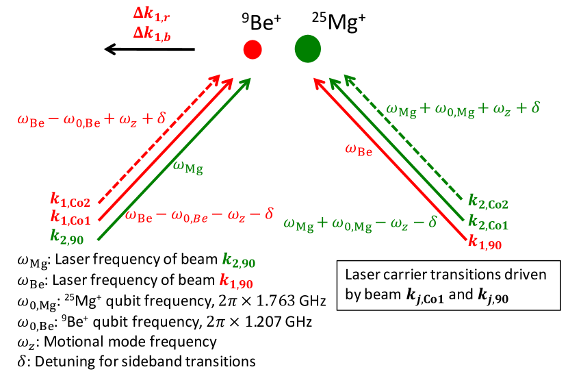
The laser beam configurations to induce coherent Raman transitions are analogous for each element; for brevity, we will only describe the configuration for 9Be+ (red in Fig. 1). Three laser beams, labeled by , and , are derived from a single laser with wavelength 313 nm. Beams and are copropagating such that their wave vector differences with respect to the beam are aligned along the trap axis. In this configuration, only the axial motional modes interact with the laser beams. The two copropagating beams induce the detuned blue and red sideband Raman transitions, respectively, when paired with the beam to implement the MS interaction (see Methods).
One important consideration in creating deterministic mixed-element entanglement with the MS interaction driven by multiple laser fields is the control over the relative optical phases at the ions’ locations. The basis states , , and the state-dependent forces that are applied to them (see Methods) depend on the optical phases of the beams , , and () at the ion positions. Beams and are generated in the same acousto-optic modulator (AOM), one for each ion species, and travel nearly identical paths. However, the beams take a substantially different path to reach the ions’ locations. Temperature drift and acoustic noise cause changes in the different beam paths that lead to phase fluctuations in the MS interaction. These fluctuations are slow on the timescale of a single gate but substantial over the course of many experiments. To suppress these effects, we embed the MS interaction in a Ramsey sequence implemented with two carrier pulses induced by and for each qubit Lee05 (blue-dashed box in Fig. 2.(a)). The first set of pulses maps the and states of each qubit onto the and states, whose phases are synchronized with the MS interaction. The final set of pulses undoes this mapping such that the action of this sequence is independent of the path length differences as long as the differences are constant during the entire sequence. In this case, the sequence produces a phase gate that implements , , , and . Such a phase gate could also be implemented as in Ref. [(9)] (on qubits with magnetic-field-sensitive transitions). This requires fewer laser beams but adds the technical difficulty of synchronizing the state-dependent forces at the ion locations for both species.
Before applying the gate, the ions are first Doppler cooled in all three directions. The axial motional modes are further cooled to near the ground state by Raman sideband cooling on the 9Be+ ion Monroe1995 . State initialization into the qubits’ states and qubit state readout are described in Methods. After each experiment repetition, we measure one of the possible states: , , , or .
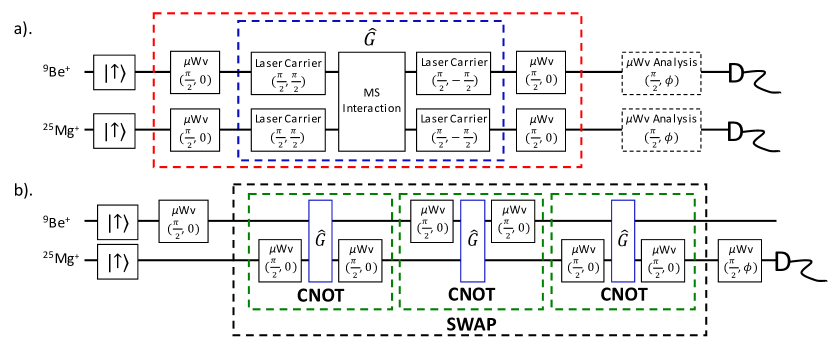
In a first experiment, we prepare the Bell state with the MS interaction (Fig. 1) and determine its fidelity by measuring the qubit populations and the contrast of the parity oscillation by applying “analysis” pulses Sackett2000 . The analysis pulses are laser carrier transitions induced by the non-copropagating laser beams and such that the relative phase defining the basis states of MS interaction is stable with respect to that of the analysis pulses for each experiment repetition. We determine a Bell state fidelity of . We also create a Bell state by applying microwave carrier pulses on each qubit before and after the operation (red-dashed box in Fig. 2(a.)) achieving a fidelity of . Following the procedure of Ref. [(24)], we perform a CHSH-type Bell-inequality test CHSH1969 on this state achieving a sum of correlations of . This inequality, measured on an entangled system consisting of different elements, agrees with the predictions of quantum mechanics while eliminating the detection loophole but not the locality loophole Rowe2001 .
The imperfections of the entangled states can be attributed to multiple causes which we investigate through calibration measurements and numerical simulation. We estimate the error from imperfect state preparation and detection to be (see Methods). Other errors are spontaneous photon scattering Ozeri2007 of 25Mg+ () and 9Be+ (), and heating of the motional mode due to electric field noise () Turchette2000 . Other known error sources include imperfect single-qubit pulses, off-resonant coupling to spectator hyperfine states and the other motional modes, mode frequency fluctuations, qubit decoherence due to magnetic field fluctuations, laser intensity fluctuations, optical phase fluctuations, and calibration errors. Each of these sources contributes error on the order of or less. We find close agreement between the experimental data and numerical simulations that include the listed imperfections.
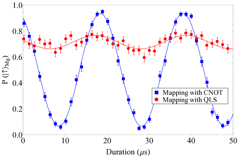
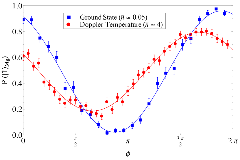
We use to construct a CNOT gate by applying microwave pulses on one of the qubits before and after (green-dashed boxes in Fig. 2(b.)) and use it to demonstrate qubit state mapping. The “target” of the CNOT gate is the qubit to which the single-qubit pulses are applied. The CNOT gate inherits the robustness against motional excitation from the MS gate Sorenson99 ; Sorenson2000 ; Milburn1999 ; Solano1999 . We compare the CNOT gate with the method used in conventional QLS procedure where a red-sideband pulse is first applied to the 9Be+ ion followed by a red-sideband pulse to the 25Mg+ ion Schmidt2005 . Both procedures are calibrated for the motional mode ground state. Figure 3 shows Rabi flopping of the 9Be+ qubit as detected on the 25Mg+ ion, which is initially prepared in the state. For the ions’ motional modes cooled to Doppler temperature (mean occupation number ), the contrast of conventional QLS method (red dots) is reduced significantly compared to transfer with CNOT gate (blue squares). In both of these mapping procedures the 9Be+ qubit phase information is not accessible on the 25Mg+ ion. To preserve this phase information, we construct a SWAP gate that interchanges the quantum state of the two qubits NielsonChuang with three CNOT gates. Figure 2.(b) shows the pulse sequence of a Ramsey-type experiment where the first Ramsey (microwave) pulse is applied to the 9Be+ ion and the second (microwave) pulse is applied to the 25Mg+ ion after implementing the SWAP gate. Ramsey fringes for the ions’ axial motional modes initialized to near the ground state (, blue squares) and Doppler cooled (, red dots) are shown in Fig. 4. The contrast at Doppler temperature is reduced because the Lamb-Dicke limit is not rigorously satisfied. Through simulation with and without the measured 25Mg+ qubit decoherence, we determine that the loss of contrast for the SWAP gate due to this decoherence is approximately 2 %. For all three methods, the contrasts could be somewhat improved by calibrating all gates for the given motional temperature.
In summary, we have demonstrated a mixed-element entangling gate where we employ a Ramsey sequence to suppress loss of fidelity of the output state due to low-frequency optical path length fluctuations Lee05 . Using this gate, we implement CNOT and SWAP operations between qubit elements which are relatively robust against thermal excitation of the motion. These and related techniques are potentially useful for building a large scale processor or quantum network utilizing the advantageous properties of different ion species MonroeandKim2013 ; Monroe2014 . The entangling technique should also be applicable to qubits with optical transitions (e.g. Ca+ ion or Sr+ ion), or a combination of hyperfine qubits and optical qubits, which can also make this technique useful for readout in quantum logic clocks Chou2010 .
Similar work has also been carried out at the University of Oxford Ballance2015 on different isotopes of Ca+ where the same laser beams can manipulate both isotopes simultaneously. The method presented here uses two substantially different sets of laser beams and ion spectra illustrating that cross-talk between operations on different species can be negligible, and could be applied to take advantage of each species’ desirable features.
I Methods
I.1 Geometric phase gate
The Mølmer-Sørensen (MS) protocol Sorenson99 ; Sorenson2000 ; Milburn1999 ; Solano1999 requires simultaneous excitation of a blue sideband transition with a detuning of and a red sideband transition with a detuning of for a selected motional mode (Fig. 1). The excitation creates a forced harmonic oscillator interaction and displaces the motional wavefunction in phase space in a manner that is dependent on the internal qubit states. If the different displacements enclose a loop, the qubit states pick up a geometric phase proportional to the state-dependent area of the enclosed loop. We create an entangling logic gate by choosing appropriate geometric phase differences between different qubit states.
Laser fields are used to induce coherent stimulated-Raman transitions between the qubit states of each ion and the shared quantized degrees of motion bible . For each qubit we can excite carrier transitions that induce spin-flips without changing the motional Fock state . A blue (red) sideband excitation () flips the spin while adding (removing) a quantum of motion by detuning the fields from the carrier transition frequency by the motional frequency in the positive (negative) direction. The relative frequencies, phases, and intensities of each set of laser beams (Fig. 1) for each qubits can be adjusted with AOMs which are computer controlled. The 9Be+ Raman laser beams with a wavelength of 313 nm are approximately GHz red detuned from the S1/2 to P1/2 electronic state transition. The 280 nm Raman laser beams for 25Mg+ ion are approximately GHz blue detuned from the S1/2 to P3/2 electronic state transition. Carrier transitions can also be implemented by microwave fields delivered from an antenna located outside the vacuum chamber.
After transforming into the respective interaction frames of both qubits as well as that of the shared motional mode of motion, and dropping high-frequency terms in the rotating-wave approximation, we can write the interaction in the Lamb-Dicke limit as bible
where denotes the two different ion species, where is the carrier resonance Rabi frequency. The Lamb-Dicke parameter is equal to , where is the mode amplitude of the jth ion and , is the mass and is the frequency of the selected normal mode. The spin raising operator is and is the creation operator for the relevant (harmonic) motional mode.
The phases of the red (r) and blue (b) sideband interactions are where and are the differences in wave vectors and phases of the optical fields driving the red and blue sideband transitions respectively, and is the equilibrium position for the jth ion. After setting and , and writing , the geometric phases accumulated after a duration of for the four and basis states (defined as the eigenstates of ) are
| (1) |
To maximize entangling gate speed, the geometric phases for the different parity qubit states in Eq. 1 are set to differ by . This is accomplished by adjusting the phases of the radio frequencies driving the AOMs.
There are two axial modes: the lower frequency mode ( MHz), where the ions oscillate in phase, and the higher frequency mode ( MHz), where the ions oscillate out of phase. The Lamb-Dicke parameter for the 9Be+ (25Mg+) ion is 0.156 (0.265) and 0.269 (0.072), respectively, for the two modes. We use the in-phase mode for our demonstration because for the 25Mg+ ion, it has a larger normal mode amplitude compared to the out-of-phase mode. This results in less spontaneous emission error for a given strength of the state-dependent force. Gate time is approximately 35 s.
I.2 Calibration procedure for phase gate
To produce the phase gate , the phases of the pulses for the Ramsey sequence must be referenced to the basis states of the MS interaction defined by the optical phases. The phases must also account for the AC Stark shifts induced by the laser beams that are used for the MS interaction.
To calibrate these phases, we first perform the pulse sequence shown in the blue-dashed box of Fig. 2.(a) with the MS interaction pulses detuned far off-resonant from the red and blue sideband transitions such that they only induce AC Stark shifts on the qubits. Starting with the input state , we set the phases of the final laser pulses such that the action of this pulse sequence returns each qubit to the state. Then, we perform this sequence with the MS interactions correctly tuned and vary the phases of the MS interactions. Again, in this case we look for the phase that maps the input state back to itself. We verify the action of this operation by creating a Bell state with the pulse sequence shown in Fig. 2.(a).
I.3 Qubit state preparation and readout
For qubit state preparation, the 9Be+ ion is optically pumped to the state followed by Doppler cooling implemented by driving the S P cycling transition with a polarized light. Similarly, we optically pump the 25Mg+ ion to the state and apply Doppler cooling on the S P transition. For ground state initialization of the axial motional modes, Raman sideband cooling is applied to the 9Be+ ion Monroe1995 . To transfer the 9Be+ state to the state, we use microwave composite pulse sequences that are robust against transition detuning errors. These consist of resonant , , pulses Levitt1986 , where the first entry denotes the angle the state is rotated about a vector in the x-y plane of the Bloch sphere and the second angle represents the azimuthal angle for the rotation axis. With analogous sequences, we first transfer the 25Mg+ from the state to the state, and then to the state.
The state-dependent resonance-fluorescence detection technique is accomplished with an achromatic lens system designed for 313 nm and 280 nm Huang2004 . We sequentially image each ion’s fluorescence onto a photomultiplier tube. After reversing the initial mapping procedures to put the states back in the respective cycling transition ground states, we apply the Doppler cooling beams. The fluorescing or “bright” state of this protocol therefore corresponds to the state of each ion. The state of each qubit is transferred to and for the 9Be+ and 25Mg+, respectively, with microwave carrier pulses. These states are “dark” to the detection beams and correspond to the state. This “shelving” technique is used to minimize the overlap of the bright and dark state photon count probability distributions. With detection durations of 330 s for 9Be+ and 200 s for 25Mg+, we detect on average 30 photons for each ion when they are in the bright state and 3.5 photons (predominantly from background light) when they are in the dark state. The qubit state is determined by choosing a photon count threshold such that the states are maximally distinguished. The state preparation and detection error of reported in the main text includes errors due to the threshold detection protocol (false determination of each detected state being in the other state) and the infidelities of the microwave transfer pulses.
Acknowledgements.
We thank J. Bollinger and D. Hume for helpful comments on the manuscript. This work was supported by the Office of the Director of National Intelligence (ODNI) Intelligence Advanced Research Projects Activity (IARPA), ONR, and the NIST Quantum Information Program. Y. Wan is supported by the U.S. Army Research Office through MURI grant W911NF-11-1-0400. This paper is a contribution by NIST and not subject to U.S. copyright.II Author Contributions
T.R.T. and J.P.G. conceived and designed the experiments, developed components of the experimental apparatus, collected and analyzed data. T.R.T. wrote the manuscript. Y.L., Y.W., and R.B. contributed to the development of experimental apparatus. D.L. and D.J.W. directed the experiment. All authors provided important suggestions for the experiments, discussed the results, and contributed to the editing of the manuscript.
III Author Information
The authors declare no competing financial interests. Correspondence and requests for materials should be addressed to T.R.T. (tingrei.tan@nist.gov).
References
- (1) Wallquist, M., Hammerer, K., Rabl, P., Lukin, M., Zoller, P. Hybrid quantum devices and quantum engineering. Phys. Scr. T137, 014001 (2009).
- (2) Barrett, M. D. et al. Sympathetic cooling of 9Be+ and 24Mg+ for quantum logic. Phys. Rev. A 68, 042302 (2003).
- (3) Lin, Y. et al. Dissipative production of a maximally entangled steady state of two quantum bits. Nature 504, 415-418 (2013).
- (4) Hume, D. B. et al. High-fidelity adaptive qubit detection through repetitive quantum nondemolition measurements. Phys. Rev. Lett. 99, 120502 (2007).
- (5) Sørensen, A. & Mølmer, K. Quantum computation with ions in thermal motion. Phys. Rev. Lett. 82, 1971-1974 (1999).
- (6) Sørensen, A. & Mølmer, K. Entanglement and quantum computation with ions in thermal motion. Phys. Rev. A 62, 022311 (2000).
- (7) Milburn, G. J., Schneider, S., James, D. F. V. Ion trap quantum computing with warm ions. Fortschr. Phys. 48, 801-810 (2000).
- (8) Solano, E., de Matos Filho, R. L., Zagury, N. Deterministic Bell states and measurement of the motional state of two trapped ions. Phys. Rev. A 59, R2539-R2543 (1999).
- (9) Leibfried, D. et al. Experimental demonstration of a robust, high-fidelity geometric two ion-qubit phase gate. Nature 422, 412-415 (2003).
- (10) Barenco, A. et al. Elementary gates for quantum computation. Phys. Rev. A 52, 3457-3467 (1995).
- (11) Bremner, M. J. et al. Practical scheme for quantum computation with any two-qubit entangling gate. Phys. Rev. Lett. 89, 247902 (2002).
- (12) Zhang, J. Vala, J. Sastry, S. & Whaley, K. B. Exact two-qubit universal quantum circuit. Phys. Rev. Lett. 91, 027903 (2003).
- (13) Nielson, M. A. & Chuang, I. L. Quantum Computation and Quantum Information (Cambridge Univ. Press, Cambridge, 2000).
- (14) Schmidt, P. O. et al. Spectroscopy using quantum logic. Science 309, 749-752 (2005).
- (15) Clauser, J. F., Horne, M. A., Shimony, A., Holt, R. A. Proposed experiment to test local hidden-variable theories. Phys. Rev. Lett. 23, 880-884 (1969).
- (16) Monroe, C. et al. Large-scale modular quantum-computer architecture with atomic memory and photonic interconnects. Phys. Rev. A 89, 022317 (2014).
- (17) Moehring, D. L. et al. Quantum networking with photons and trapped atoms. JOSA B 24, 300-315 (2007)
- (18) Wineland, D. J. et al., J. Res. Natl. Inst. Stand. Technol. 103, 259-328 (1998).
- (19) Schulte, M., Lörch, N. , Leroux, I. D., Schmidt, P. O., Hammerer, K. Quantum algorithmic readout in multi-ion clocks. arXiv:1501.06453 (2015).
- (20) Langer, C. et al. Long-lived qubit memory using atomic ions. Phys. Rev. Lett. 95, 060502 (2005).
- (21) Lee, P. J. et al. Phase control of trapped ion quantum gates. J. Opt. B 7, S371-S383 (2005).
- (22) Monroe, C. et al. Resolved-sideband Raman cooling of a bound atom to the 3D zero-point energy. Phys. Rev. Lett. 75, 4011-4014 (1995).
- (23) Sackett, C. A. et al. Experimental entanglement of four particles. Nature 404, 256-259 (2000).
- (24) Rowe, M. A. et al. Experimental violation of a Bell’s inequality with efficient detection. Nature 409, 791-794 (2001).
- (25) Ozeri, R. et al. Errors in trapped-ion quantum gates due to spontaneous photon scattering. Phys. Rev. A 75, 042329 (2007).
- (26) Turchette, Q. A. et al. Heating of trapped ions from the quantum ground state. Phys. Rev. A 61, 063418 (2000).
- (27) Monroe, C. & Kim, J. Scaling the ion trap quantum processor. Science 339, 1164-1169 (2013).
- (28) Chou, C. W., Hume, D. B., Koelemeij, J. C. J, Wineland, D. J., Rosenband, T. Frequency comparison of two high-accuracy Al+ optical clocks. Phys. Rev. Lett. 104, 070802 (2010).
- (29) Ballance, C. J. et al. Hybrid quantum logic and a test of Bell’s inequality using two different atomic species. arXiv:1505:04014 (2015).
- (30) Levitt, M. H. Composite Pulses. Prog. NMR Spectrosc. 18, 61-122 (1986).
- (31) Huang, P. & Leibfried D. Achromatic catadioptric microscope objective in deep ultraviolet with long working distance. Proc. SPIE 5524, 125-133 (2004).