Cavity-enhanced coherent light scattering from a quantum dot
Abstract
Resonant excitation of atoms and ions in macroscopic cavities has lead to exceptional control over quanta of light Haroche06 ; Wineland13 . Translating these advantages into the solid state with emitters in micro-cavities promises revolutionary quantum technologies in information processing and metrology. Key is resonant optical reading and writing from the emitter-cavity system. However, it has been widely expected that the reflection of a resonant laser from a micro-fabricated -sized cavity would dominate any quantum signal. Here we demonstrate coherent photon scattering from a quantum dot in a micro-pillar. The cavity is shown to enhance the fraction of light which is resonant scattered towards unity, generating anti-bunched indistinguishable photons a factor of 16 beyond the time-bandwidth limit, even when the transition is near saturation. Finally, deterministic excitation is used to create 2-photon N00N states with which we make super-resolving phase measurements in a photonic circuit.
pacs:
Valid PACS appear hereEngineering cavities around an emitter modifies the local density of optical states, changing the emission pattern and radiative decay rate Buckley14 . It has been proposed that cavities can also accelerate the rate at which a spin may be prepared Loo11 , increase photon-spin coupling Hu08 and enhance Raman scattering Sweeney14 under resonant optical fields. A reduced radiative lifetime also leads to an increase in the photon fraction that can be resonantly scattered Nguyen11 ; Konthasinghe12 leading to an “ideal” quantum light source with high efficiency and high coherence.
Three dimensional pillar micro-cavities allow a cavity-induced reduction in by an order of magnitude Gerard98 ; Gazzano13 ; Ulhaq12 ; Ates09 ; Santori02 ; Pooley12 ; Moreau01 . Unlike previous studies Ates09 ; Ulhaq12 we excite and collect photons from the cavity along the axis that couples efficiently to the light field, illustrating the potential of this system as a spin-photon interface and a source of indistinguishable single photons.
It is possible to suppress the laser signal at the detectors whilst efficiently collecting the emission from an etched micro-cavity using polarisation filtering, Figure 1a. Thus far, this technique has been limited to optically smooth and flat samples Matthiesen12 ; Kuhlmann13 ; He13 , for which a cavity enhancement is not observed. We employ a pillar micro-cavity (Figure 1b) with a 2.25 m diameter, which is close to optimal for maximizing the photon extraction efficiency Pelton02 ; Gazzano13 . The mode of the device we study has a quality factor, , of 8,900 which is reduced from the of the unetched cavity. Imperfections in the cavity sidewalls which are visible in Figure 1b are a possible source of optical loss in the mode Gerard98 ; Pelton02 . Rotating polariser 2 in the photon detection path it was possible to suppress the laser collected by a factor of 103.
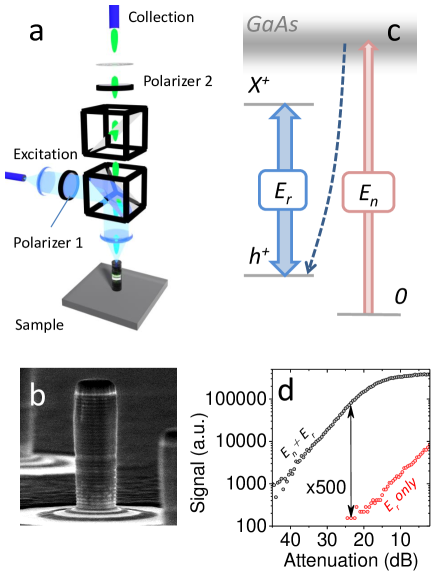
Figure 1d shows data from this micro-cavity, which contains an transition emitting at 934 nm. Under only resonant illumination (the laser denoted in Figure 1c) we collect a total absence of emission from , only weak poissonian laser (red data points, Figure 1d). However, the addition of 100 pW of illumination at 850 nm (laser ) “activates” the resonant emission (RE). We attribute this to the capture of a single hole into the ground state by the process shown in Figure 1c. This is to be contrasted with the optical gating of neutral excitons, in which it has been reported RE can be suppressed when a charge tunnels into the dot from a nearby defect Nguyen12 . The ability to switch on the RE with this weak non-resonant light enables us to quantify the intensity of the RE relative to the laser. For the device discussed here the RE collected is 500 times greater than the laser (Figure 1d), but can reach a factor of 3000 in other cavities.
The resonant laser power required to observe RE in these high- cavities is 3 orders of magnitude lower than for planar cavities with 70 Lee15 . This is to be expected given the efficient photon-in-coupling and higher quality factor. In addition, the Purcell effect has reduced the lifetime of the single quantum emitter, broadening the transition to 6.14 0.19 eV (approximately 5 times greater than non-cavity enhanced emitters in this sample).
Figure 2a shows the result of a Hanbury-Brown and Twiss auto-correlation measurement of recorded under CW excitation at a Rabi frequency 0.83 GHz. The data is fitted with the well-known equations for under coherent excitation Cohen98 ; Nguyen12 ; Flagg09 , including an additional charging-induced bunching effect Santori04 . This confirms the dominance of the anti-bunched quantum emission at the detectors. The spectrum of the RE in Figure 2b (black data points), appears close to the instrument resolution (0.78 eV, red line). There is no evidence of the emitter linewidth in this spectrum. This is a clear signature of Resonant Rayleigh Scattering (RRS) by the two level system. A least-squares fit gives a spectral width of 0.37 0.03 eV over the system response, so the coherently scattered photons are narrower than the radiative linewidth by a factor of 16.
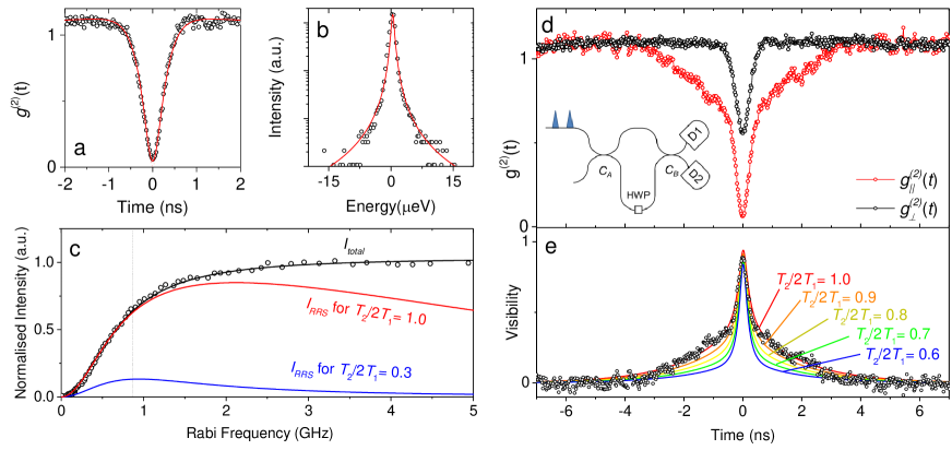
Figure 2c shows the total intensity, , emitted by the transition as a function of Rabi frequency. One advantage of cavity-enhancement is that emission due to RRS, , is greatly increased. The fraction of the total emitted light due to RRS Cohen98 ; Nguyen11 is
| (1) |
where is the radiative lifetime and . For an emitter with no cavity enhancement we typically see 1 ns and 0.6 ns Lee15 which would lead to a variation in as shown in Figure 2c in blue. The maximum fraction is 0.3, which can only be achieved well below saturation. For a cavity enhanced source the fraction is close to unity (Figure 2c, red). We observe in Figure 2b that at 0.83 GHz, when is 0.65 of its maximum value, the RRS dominates the spectrum.
Further confirmation of the character of the emitted light can be obtained by two-photon interference measurements. Figure 2d shows the result of a continuous-wave two-photon interference measurement Patel10 ; Ates09 at 0.83 GHz. Light from source is passed to a fibre-optic Mach-Zehnder interferometer with a delay of 10.4 ns and a half-wave plate (HWP) in one arm (insert to Figure 2d). This enabled photons emitted at a time separation of 10.4 ns to take the two paths through the interferometer and meet at the final coupler, . Dependent on the HWP photons meeting at this coupler can have parallel or orthogonal polarization and an auto-correlation on the outputs of the interferometer measures the degree of indistinguishability. The difference in the two measurements is quantified by the interference visibility which is shown in Figure 2e. The maximum visibility observed is 0.89, and the shape of the visibility plot is determined by the first order coherence of the photons Cohen98 . We fit this data Proux15 ; Cohen98 for a range of values of . The calculation provides a remarkably good fit to the data for = 1.0. This shows the source is delivering highly indistinguishable photons, and that the Purcell effect has enhanced the RRS part of the spectrum.
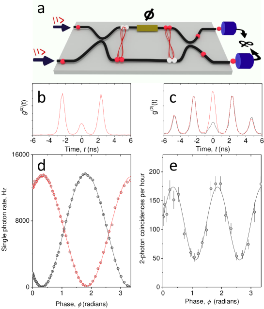
Next, we discuss the operation of the source under pulsed optical excitation to create on-demand single photons, indistinguishable photon pairs and N00N states (Figure 3). Optical pulses of length 57 ps resonantly excite the transition and Rabi oscillations in the detected RE are observed as a function of the incident field amplitude. The source was driven with 0.71- pulses to provide a near-deterministic excitation and an optimal signal-to-background level He13 ; Lee15 . When two pulses are used to excite the source at a time separation of 2.36 ns the emitted photons can again be interfered to determine their indistinguishability. For a pulsed demonstration of 2-photon interference a more useful parameter is Santori02 which is the probability of generating two photons in either of the two pulses, divided by the probability of generating two single photons. A measurement of = 0.167 0.005 is shown in Figure 3b. For reference 0.165 0.004, where the probability of multi-photon emission during a single laser pulse results in a deviation from the ideal value. When these two photons interfere with with parallel or orthogonal polarisation (black and red lines in Figure 3c) the difference in coincidences is indicative of a high degree of indistinguishability. Following analysis Santori02 , we determine a two-photon overlap .
Finally, we use this source to build a 2-photon N00N state, which is the proto-typical quantum state used for phase-enhanced measurementDowling08 ; Boto00 ; Matthews09 . The two photons are fed into a silicon oxy-nitride photonic chip as shown in Figure 3a which delivers sub-wavelength control of path lengths and stability. Two indistinguishable photons interfere at the first coupler and exit together in the superposition state . These two paths then experience a relative phase shift, , transforming the state to . Thus, super-resolution is achieved because the phase shift introduced to the two-photon state is twice that of a single photon, and can be measured by recombining both paths on a final coupler.
Figure 3d shows the single photon count rate at each output of the photonic chip as a function of the phase shift when light is only inserted to one of the inputs. The oscillations have a visibility of 0.98, reflecting the balanced splitting of the couplers and the two paths through the interferometer. When single photons are fed into both inputs a measurement that post-selects two-photon coincidences between the two outputs, Figure 3e, clearly displays a doubled rate of oscillation with phase, relative to the single photon case. This is the signature of super-resolution. The minimum coincidence rate observed in Figure 3e is determined by the value . Losses in the optics and detectors preclude the observation of phase super-sensitivity, so this effect is limited to the post-selected measurements. However, we anticipate that the future integration of single photon sources directly onto the chip Murray15 could increase the efficiency of the photon coupling.
In conclusion, we have demonstrated coherent excitation of a cavity-QED enhanced emitter using the optimal axis for coupling in and out light. We observe indistinguishable coherent photon scattering even as the transition is driven near saturation. This result shows how the combination of coherent excitation and cavity-QED can lead to a bright and coherent photon source.
Acknowledgements
The EPSRC partly funded the MBE machine used to grow the sample. EM and TM acknowledge support by the EU Marie Curie Initial Training Network PICQUE, Grant No. 608062. JL acknowledges support from the EPSRC CDT in Photonic Systems Development.
References
- (1) S. Haroche and J.-M. Raimond. Exploring the quantum: Atoms, Cavities and Photons. Oxford Graduate Texts, (2006).
- (2) D. J. Wineland, Rev. Mod. Phys. 85, 1103 (2013).
- (3) S. Buckley, K. Rivoire, and J. Vuckovic, Rep. Prog. Phys. 75, 126503 (2014).
- (4) V. Loo, L. Lanco, O. Krebs, P. Senellart, and P. Voisin, Phys. Rev. B 83, 033301 (2011).
- (5) C. Y. Hu, W. J. Munro, and J. G. Rarity, Phys. Rev. B 78, 125318 (2008).
- (6) T. M. Sweeney, S. G. Carter, A. S. Bracker, M. Kim, C. S. Kim, L. Yang, P. M. Vora, P. G. Brereton, E. R. Cleveland, and D. Gammon, Nature Photonics 8, 442–447 (2014).
- (7) H. S. Nguyen, G. Sallen, C. Voisin, P. Roussignol, C. Diederichs, and G. Cassabois, Applied Physics Letters 99, 261904 (2011).
- (8) K. Konthasinghe, J. Walker, M. Peiris, C. K. Shih, Y. Yu, M. F. Li, J. F. He, L. J. Wang, H. Q. Ni, Z. C. Niu, and A. Muller, Phys. Rev. B 85, 235315 (2012).
- (9) J. M. Gerard, B. Sermage, B. Gayral, B. Legrand, E. Costard, and V. Thierry-Mieg, Phys. Rev. Lett. 81, 1110 (1998).
- (10) O. Gazzano, S. M. de Vasconcellos, C. Arnold, A. Nowak, E. Galopin, I. Sagnes, L. Lanco, A. Lema tre, and P. Senellart, Nature Communications 73, 1425 (2013).
- (11) A. Ulhaq, S. Weiler, S. M. Ulrich, R. Rosbach, M. Jetter, and P. Michler, Nature Photonics 6, 238–242 (2012).
- (12) S. Ates, S. M. Ulrich, S. Reitzenstein, A. Löffler, A. Forchel, and P. Michler, Phys. Rev. Lett. 103, 167402 (2009).
- (13) C. Santori, D. Fattal, J. Vuckovic, G. S. Solomon, and Y. Yamamoto, Nature 419, 594–597 (2002).
- (14) M. A. Pooley, D. J. P. Ellis, R. B. Patel, A. J. Bennett, K. H. A. Chan, I. Farrer, D. A. Ritchie, and A. J. Shields, Applied Physics Letters 100, 211103 (2012).
- (15) E. Moreau, I. Robert, J. M. Gérard, I. Abram, L. Manin, and V. Thierry-Mieg, Applied Physics Letters 79, 2865–2867 (2001).
- (16) C. Matthiesen, A. N. Vamivakas, and M. Atatüre, Phys. Rev. Lett. 108, 093602 (2012).
- (17) A. V. Kuhlmann, J. Houel, A. Ludwig, L. Greuter, D. Reuter, A. D. Wieck, M. Poggio, and R. J. Warburton, Nature Physics 9, 570–575 (2013).
- (18) Y. He, Y. He, Y. Wei, D. Wu, M. Atatüre, C. Schneider, S. Höfling, M. Kamp, C.-Y. Lu, and J.-W. Pan, Nature Nanotechnology 8, 213–217 (2013).
- (19) M. Pelton, C. Santori, J. Vuckovic, B. Zhang, G. S. Solomon, J. Plant, and Y. Yamamoto, Phys. Rev. Lett. 89, 233602 (2002).
- (20) H. S. Nguyen, G. Sallen, C. Voisin, P. Roussignol, C. Diederichs, and G. Cassabois, Phys. Rev. Lett. 108, 057401 (2012).
- (21) J. P. Lee, A. J. Bennett, D. J. P. Ellis, I. Farrer, D. A. Ritchie, and A. J. Shields, under review (2015).
- (22) C. Cohen-Tannoudji, J. Dupont-Roc, and G. Grynberg. Atom-Photon Interaction - Basic Processess and Applications. Wiley-VCH, (1998).
- (23) E. B. Flagg, A. Muller, J. W. Robertson, S. Founta, D. G. Deppe, M. Xiao, W. Ma, G. J. Salamo, and C. K. Shih, Nature Physics 5, 203–207 (2009).
- (24) C. Santori, D. Fattal, J. Vuckovic, G. S. Solomon, E. Waks, and Y. Yamamoto, Phys. Rev. B 69, 205324 (2004).
- (25) R. B. Patel, A. J. Bennett, K. Cooper, P. Atkinson, C. A. Nicoll, D. A. Ritchie, and A. J. Shields, Nanotechnology 21, 274011 (2010).
- (26) R. Proux, M. Maragkou, E. Baudin, C. Voisin, P. Roussignol, and C. Diederichs, Phys. Rev. Lett. 114, 067401 (2015).
- (27) J. P. Dowling, Contemporary Physics 49, 2 (2008).
- (28) A. N. Boto, P. Kok, D. S. Abrams, S. L. Braunstein, C. P. Williams, and J. P. Dowling, Phys. Rev. Lett. 85, 2733 (2000).
- (29) J. C. F. Matthews, A. Politi, A. Stefanov, and J. L. O’Brien, Nature Photonics 3, 346–350 (2009).
- (30) E. Murray, D. J. P. Ellis, T. Meany, F. F. Flother, J. P. Lee, J. P. Griffths, G. A. C. Jones, I. Farrer, D. A. Ritchie, A. J. Bennett, and A. J. Shields, arXiv:1507.00256 (2015).