Vertical-Cavity In-plane Heterostructures: Physics and Applications
Abstract
We show that the in-plane heterostructures realized in vertical cavities with high contrast grating (HCG) reflector enables exotic configurations of heterostructure and photonic wells. In photonic crystal heterostructures forming a photonic well, the property of a confined mode is determined by the well width and barrier height. We show that in vertical-cavity in-plane heterostructures, anisotropic dispersion curvatures plays a key role as well, leading to exotic effects such as a photonic well with conduction band like well and a valence band like barrier. We investigate three examples to discuss the rich potential of this heterostructure as a platform for various physics studies and propose a system of two laterally coupled cavities which shows the breaking of parity-time symmetry as an example.
pacs:
42.55.Px, 42.55.Sa, 42.60.Da, 73.21.FgThe vertical cavity is a rich platform for fundamental physics studies of light-matter interaction such as cavity quantum electrodynamics (QED) Gérard et al. (1998); Vahala (2003) and cavity polaritons Deng et al. (2002); Christopoulos et al. (2007), as well as various applications including vertical-cavity surface-emitting lasers (VCSELs) Moser et al. (2013); Westbergh et al. (2009), single-photon light sources Pelton et al. (2002), and Si-integrated on-chip lasers Chung and Mørk (2010). Recently, it has been reported that the dispersion of a vertical cavity, i.e., the relation between the frequency and wavevector of a cavity mode, can be engineered by using the high-index-contrast grating (HCG) as reflector and designing the dispersion of HCG Wang et al. (2015); Zhang et al. (2015). Furthermore, a heterostructure can be formed in direction by varying HCG parameters, as shown in Fig. 1(a) Sciancalepore et al. (2011). In those reports, the discussions are focused on the dispersion profile in space along the direction or the profile of dispersion band edge in real space along the direction. The direction represents a direction perpendicular to the grating lines, as defined in Fig. 1.
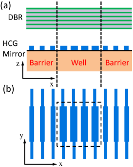
Here, we note the anisotropic dispersion curvatures of HCG-based vertical cavities along and directions and investigate their exotic impacts on the properties of vertical-cavity in-plane (VCI) heterostructures, which are not possible nor feasible in semiconductor and photonic crystal (PhC) heterostructures. The dispersion curvature is the second order derivative of the frequency of a propagating mode with respect to the in-plane wavevector and its inverse can be interpreted as an effective photon mass along the wavevector direction. As discussed below, two dispersion curvatures along and directions can be feasibly designed in HCG-based cavities to have a specific positive, zero, or negative value. Furthermore, a heterostructure with significantly different dispersion curvatures (even a different signs of curvatures) in each side of the heterostructure interface can be formed. In comparison, in semiconductors, the effective masses along different directions have values quite similar. In PhCs, since only the waveguide-type cavities are practically allowed for a laser cavity to avoid excessive surface recombination, only one effective mass is available along the light propagation direction. In addition, a heterostructure with opposite sign of effective masses in each side of the heterostructure interface is not possible for both semiconductor and PhC heterstructures. Therefore, with HCG-based VCI heterstructures, one may design a well structure with an extra degree of freedom of effective mass and a control over the direction of energy flow. These identified differences and consequent potentials have motivated the study of this paper.
This paper is organised as follows. Firstly, we derive an analytic expression for the dispersion of the entire cavity hereafter referred to as cavity dispersion. This expression decomposes the cavity dispersion into the contributions from each mirror and the waveguide that is a nominal cavity between two mirrors, hereafter referred to as mirror and waveguide dispersions, respectively. Using this expression, we quantitatively discuss the properties of anisotropic dispersion curvatures as well as an optimal thickness of the nominal cavity layer. Then, we investigate three characteristic VCI photonic well structures to study the physics of VCI heterostructures. In the first and second structures, all the well and barrier regions have positive and negative dispersion curvatures, respectively. These case studies explain how the order and spacing between the transverse mode frequencies are determined by the sign and magnitude of dispersion curvatures. As potential applications of these properties, the engineering of photon-photon resonances for achieving a high speed laser is discussed. In the third case, the well and barrier regions have opposite signs of dispersion curvatures, which shows the possibility of designing a heterostructure with another degree of freedom, compared to semiconductor or PhC heterostrucutres. Based on these new insights, we propose and analyze a novel system of laterally coupled vertical cavities. This appears promising for various physics studies where coupled laser cavities are needed, since the effective mass can be controlled as another degree of freedom and the coupling direction and light output/input direction are separated, which makes the access to the information in cavities much easier. As an example, the parity-time symmetry breaking phenomenon is reported for the first time in vertical cavities.
Dispersions curvatures: In Sciancalepore et al. (2011), an expression for cavity dispersion was discussed around the Fano resonance frequencies of the HCG comprising the vertical cavity. Here, we derive a general expression which is valid at all frequencies within the HCG stopband, which is in line with discussion in Wang et al. (2015). In a vertical cavity, the mode frequency is found by solving the oscillation condition:
| (1) |
Here , , and are wavevector components of a mode in the nominal cavity layer with a refractive index , which is a layer between mirrors, and is the nominal cavity length. Note that the reflection phases from the two mirrors, and depend on the in-plane wavevectors and . The resonance frequency at normal incident denoted by is = , where . Inserting the resonance condition into Eq. (1) and Taylor-expanding it lead to:
| (2) |
where is the effective cavity length, is the phase penetration into a -th mirror, and . The represents the cavity dispersion curvature along direction. The first term of is the waveguide dispersion curvature for the round-trip propagation in the nominal cavity and always positive, while the second term of accounts for mirror dispersion curvature. The mirror dispersion curvature of HCGs can be either positive, negative, or even zero. In general, it is polarization sensitive and anisotropic.
At =1550 nm, a -long nominal air cavity has a waveguide dispersion curvature of approximately 30 m2/s. As seen in Eq. (2), it increases linearly with a longer cavity length . The mirror dispersion curvature of a typical distributed Bragg reflector (DBR) is on the order of 1 m2/s and gets smaller with a larger refractive index contrast of DBR layers. It is isotropic due to the rotational symmetry of DBR structures. Therefore, in DBR-based cavities the waveguide dispersion curvature dominates the cavity dispersion curvature and makes it always positive and isotropic, which resembles the conduction band in semiconductors. However, in the case of HCGs, the mirror dispersion curvature can be positive or negative and may be on the order of 100 m2/s or even larger. If the cavity length is short, e.g., or 2, the cavity dispersion curvature of HCG-based cavities can be positive, zero or negative, being dominated by the HCG dispersion curvature. Also, the cavity dispersion is anisotropic along and directions and depends on the incident light polarization since the HCG mirror dispersion does. Therefore, it is possible in HCG-based cavities to engineer the cavity dispersion by designing the phase response of the HCG while keeping its reflectivity high. Designing of a phase is feasible for HCGs as discussed in Carletti et al. (2011). We would note that a new type of grating reflector referred to as hybrid grating reflector Taghizadeh et al. (2014) or zero-contrast grating Magnusson (2014) has similar mirror dispersion as HCG. The hybrid grating consists of a sub-wavelength grating layer and an unpatterned layer which may includes a gain material.
The envelope approximation derived for PhC heterostructures Charbonneau-Lefort et al. (2002); Istrate and Sargent (2006) can be applied to analyze VCI heterostructures Park et al. (2015a). The effective mass defined for the envelope approximation can be related to the dispersion curvature : . Using the envelope approximation, the resonance frequency of a rectangular VCI photonic well is found as Park et al. (2015a):
| (3) |
where and are mode numbers for the and directions, respectively, and , rational factors due to the finite barrier heights, and and , the lengths of the heterostructure in and directions, respectively. This expression will be used to interpret the result of example structures below.
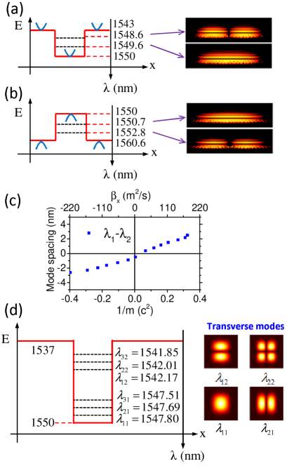
Three case studies: To study the physics of VCI heterostructures, three characteristic photonic well structures are numerically investigated. As shown in Figs. 2(a), 2(b), and 3(a), the first structure has positive dispersion curvatures for both well and barrier regions, the second has negative dispersion curvatures for both well and barrier, and the third has a mixture of positive and negative dispersion curvatures. All structures have a 0.5-long air cavity and HCGs designed to be highly reflective for TM polarized field Chung (2015). For simulations, an in-house developed three-dimensional (3D) simulator was used as explained in Taghizadeh et al. (2015), which is based on rigorous coupled wave analysis (RCWA) method Moharam et al. (1995); Li (1997) and employs absorbing boundary conditions Hugonin and Lalanne (2005).
It is well known in the VCSEL literature that higher order transverse modes have higher frequencies, i.e., shorter wavelengths due to their higher in-plane wavevectors. However, the in-plane dispersion of HCG structures can significantly modify this characteristic property. For the photonic well case with positive dispersion shown in Fig. 2(a), we have the usual situation of VCSELs; the fundamental mode has the longest wavelength. However, for the negative dispersion case shown in Fig. 2(b), the fundamental mode has a shorter wavelength than the higher order mode. Referring to Eq. (3), this observation can be interpreted like this: the higher order mode with more spatial modulation adds a larger negative kinetic energy, lowering the total energy. The positive dispersion (electron-like) and negative dispersion (hole-like) cases are analogous to the electronic quantum wells in conduction band and valence band, respectively. This observation is generalized in the result of Fig. 2(c).
Figure 2(c) plots the wavelength spacing of the two lowest transverse modes as a function of the -direction dispersion curvature in the well region. It shows that the wavelength spacing increases with a larger dispersion curvature. This observation can be understood also by referring to Eq. (3): With a smaller dispersion curvature corresponding to a larger effective mass, the kinetic energy contribution to the total energy becomes smaller, leading to a smaller energy difference between two transverse modes. Therefore, the transverse mode spacing can be controlled by engineering the dispersion of HCG, without changing the transverse mode size. This results in several interesting phenomena such as mode grouping and mode degeneracy and has a potential to innovate several applications, as discussed below.
If and largely differ, the transverse modes are grouped as shown in Fig. 2(d). In Fig. 2(d), the effective mass along direction is roughly 10 times smaller than that along direction. As a result, the second mode number for direction determines the larger wavelength spacing between groups, while the first one for direction determines the smaller wavelength spacing within a group. This mode grouping is experimentally observed in a HCG-DBR cavity laser Park et al. (2015a) and 3D simulations give the same result. The mode profiles in Fig. 2(d) are obtained by 3D simulations. Furthermore, the fundamental mode frequency and higher order mode frequencies can be made degenerate by designing the effective mass so that and [c.f., Eq. (3)]. This transverse mode-degeneracy is also confirmed by 3D simulations.
This control over transverse mode spacings can be used to boost the speed of a diode laser. Recently, the bandwidth boost of laser diodes has attracted lots of attention Graydon (2015); Mieda et al. (2015). The boost mechanism is based on the introduction of a photon-photon resonance at a frequency higher than the relaxation oscillation frequency by designing an external optical feedback and cross-gain modulation. In HCG-based vertical cavities, multiple transverse modes can be designed to have specific wavelength spacings, e.g., 0.15 nm, which determines the photon-photon resonance frequency. In this way, multiple photon-photon resonances can be introduced at designed frequencies through cross-gain modulation. For this, we need to make all transverse modes lasing, which is feasible since we can separately control the mode profile from gain profile, by using in-plane heterostructure. An external optical feedback in in-plane directions can be introduced as well. Recently, we have demonstrated a high-speed Si-integrated vertical cavity laser, using the in-plane optical feedback Park et al. (2015b).
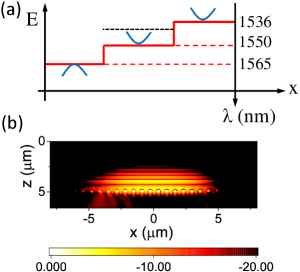
The unique possibility to design various effective masses in well and barrier regions enables exotic photonic well configurations. An interesting example is a photonic well where the effective mass sign of the barrier region is the opposite to that of the well region, e.g. hole-like barrier with electron-like well. In order to obtain a transverse mode confinement, the band edge of the barrier should be lower than that of the well. This band edge alignment is opposite to that of the Fig. 2(a) case where both barrier and well are electron-like cavities. To compare these two cases, we design and simulate a VCI heterostructure with positive effective masses in the well and right barrier and negative effective mass for the left barrier, as illustrated in Fig. 3(a). The right barrier is the same as in Fig. 3(a) case while the left barrier is the exotic configuration just described above. The mode profile is well confined in the well section, as shown in Fig. 3(b). If the left barrier band edge is moved above the well band edge, it results in unconfined mode. This example shows that HCG-based VCI heterostructure has more freedom to design photonic wells by controlling effective mass as well as band edge.
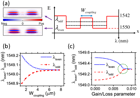
Coupled micro-cavity structures are very attractive systems due to their physically rich characteristics resulting in many interesting phenomena such as miniband formation Happ et al. (2003), heavy photons Bayindir and Ozbay (2000), coupled-cavity QED Hughes (2007), and recently parity-time (PT) symmetry breaking phenomena Peng et al. (2014). For implementation, various structures have been suggested and investigated including PhC coupled cavities Happ et al. (2003), microring resonators Peng et al. (2014); Jing et al. (2014) and vertically coupled VCSELs Stanley et al. (1994). Here, we propose a new type of laterally coupled vertical cavities, as shown in Fig. 4(a). We note that in the proposed coupled cavities the directions of the light propagation (vertical) and coupling (lateral) are separated from each other while they are in the same directions in other coupled cavities. This makes the access to the information of each cavity easier. As shown in Fig. 4(a), the coupling of two identical cavities leads to two coupled states with even and odd parities. The coupling strength can be tuned by changing the barrier width, height, or effective mass. Here, we choose the barrier width, . As shown in Fig. 4(b), with a larger coupling, i.e., smaller , the separation between two coupled state wavelengths becomes larger. As shown in Fig. 4(c), the PT symmetry of this coupled cavities can be broken by introducing a gain region in one cavity and a loss region in the other cavity, which reduces the wavelength separation. The exceptional point as indicated by a green dotted circle is a characteristic signature of PT-symmetry breaking Peng et al. (2014).
In conclusion, the in-plane dispersion curvatures of a HCG-based vertical cavities can be designed to be specific values in different directions provided that the cavity length is short, e.g., thick. We have shown that this provides another degree of freedom in designing vertical cavity in-plane heterostructures, enabling exotic heterostructures which are not possible nor feasible in semiconductor and photonic crystal counterparts, e.g. a photonic well with opposite sign of effective mass for well and barrier. Furthermore, a system of two laterally coupled vertical cavities was proposed and simulated which shows spontaneously broken parity-time symmetry.
Acknowledgements.
The authors gratefully acknowledge support from the Danish Council for Independent Research (Grant No. 0602-01885B), the Innovation Fund Denmark through the HOT project (Grant No. 5106-00013B), as well as Villum Fonden via the NATEC Centre of Excellence.References
- Gérard et al. (1998) J. Gérard, B. Sermage, B. Gayral, B. Legrand, E. Costard, and V. Thierry-Mieg, Phys. Rev. Lett. 81, 1110 (1998).
- Vahala (2003) K. J. Vahala, Nature 424, 839 (2003).
- Deng et al. (2002) H. Deng, G. Weihs, C. Santori, J. Bloch, and Y. Yamamoto, Science 298, 199 (2002).
- Christopoulos et al. (2007) S. Christopoulos, G. B. H. Von Högersthal, A. Grundy, P. Lagoudakis, A. Kavokin, J. Baumberg, G. Christmann, R. Butté, E. Feltin, J.-F. Carlin, et al., Phys. Rev. Lett. 98, 126405 (2007).
- Moser et al. (2013) P. Moser, J. Lott, P. Wolf, G. Larisch, A. Payusov, N. N. Ledentsov, and D. Bimberg, IEEE J. Sel. Top. Quantum Electron. 19, 7900406 (2013).
- Westbergh et al. (2009) P. Westbergh, J. S. Gustavsson, Å. Haglund, M. Sköld, A. Joel, and A. Larsson, IEEE J. Sel. Top. Quantum Electron. 15, 694 (2009).
- Pelton et al. (2002) M. Pelton, C. Santori, J. Vuc̆ković, B. Zhang, G. S. Solomon, J. Plant, and Y. Yamamoto, Phys. Rev. Lett. 89, 233602 (2002).
- Chung and Mørk (2010) I.-S. Chung and J. Mørk, Appl. Phys. Lett. 97, 151113 (2010).
- Wang et al. (2015) Z. Wang, B. Zhang, and H. Deng, Phys. Rev. Lett. 114, 073601 (2015).
- Zhang et al. (2015) B. Zhang, S. Brodbeck, Z. Wang, M. Kamp, C. Schneider, S. Höfling, and H. Dening, Appl. Phys. Lett. 106, 051104 (2015).
- Sciancalepore et al. (2011) C. Sciancalepore, B. B. Bakir, X. Letartre, J.-M. Fedeli, N. Olivier, D. Bordel, C. Seassal, P. Rojo-Romeo, P. Regreny, and P. Viktorovitch, J. Lightwave Technol. 29, 2015 (2011).
- Carletti et al. (2011) L. Carletti, R. Malureanu, J. Mørk, and I.-S. Chung, Opt. Express 19, 23567 (2011).
- Taghizadeh et al. (2014) A. Taghizadeh, G. C. Park, J. Mørk, and I.-S. Chung, Opt. Express 22, 21175 (2014).
- Magnusson (2014) R. Magnusson, Opt. Lett. 39, 4337 (2014).
- Charbonneau-Lefort et al. (2002) M. Charbonneau-Lefort, E. Istrate, M. Allard, J. Poon, and E. H. Sargent, Phys. Rev. B 65, 125318 (2002).
- Istrate and Sargent (2006) E. Istrate and E. H. Sargent, Rev. Mod. Phys. 78, 455 (2006).
- Park et al. (2015a) G. C. Park, W. Xue, A. Taghizadeh, E. Semenova, K. Yvind, J. Mørk, and I.-S. Chung, Laser Photon. Rev. 9, L11 (2015a).
- Chung (2015) I.-S. Chung, Opt. Express 23, 16730 (2015).
- Taghizadeh et al. (2015) A. Taghizadeh, J. Mørk, and I.-S. Chung, Opt. Express 23, 14913 (2015).
- Moharam et al. (1995) M. Moharam, T. Gaylord, E. B. Grann, and D. A. Pommet, J. Opt. Soc. Am. 12, 1068 (1995).
- Li (1997) L. Li, J. Opt. Soc. Am. 14, 2758 (1997).
- Hugonin and Lalanne (2005) J. P. Hugonin and P. Lalanne, J. Opt. Soc. Am. 22, 1844 (2005).
- Graydon (2015) O. Graydon, Nat. Photon. 9, 75 (2015).
- Mieda et al. (2015) S. Mieda, S. Shiratori, N. Yokota, W. Kobayashi, and H. Yasaka, Appl. Phys. Express 8, 022701 (2015).
- Park et al. (2015b) G. C. Park, W. Xue, M. Piels, D. Zibar, J. Mørk, E. Semenova, and I.-S. Chung, in preparation for submission (2015b).
- Happ et al. (2003) T. D. Happ, M. Kamp, A. Forchel, J.-L. Gentner, and L. Goldstein, Appl. Phys. Lett. 82, 4 (2003).
- Bayindir and Ozbay (2000) M. Bayindir and E. Ozbay, Phys. Rev. B 62, R2247 (2000).
- Hughes (2007) S. Hughes, Phys. Rev. Lett. 98, 083603 (2007).
- Peng et al. (2014) B. Peng, Ş. K. Özdemir, F. Lei, F. Monifi, M. Gianfreda, G. L. Long, S. Fan, F. Nori, C. M. Bender, and L. Yang, Nat. Phys. 10, 394 (2014).
- Jing et al. (2014) H. Jing, S. Özdemir, X.-Y. Lü, J. Zhang, L. Yang, and F. Nori, Phys. Rev. Lett. 113, 053604 (2014).
- Stanley et al. (1994) R. Stanley, R. Houdre, U. Oesterle, M. Ilegems, and C. Weisbuch, Appl. Phys. Lett. 65, 2093 (1994).