Present address: ]European Southern Observatory (ESO), Garching bei München, Germany
Performance of a radiatively cooled system for quantum optomechanical experiments in space
Abstract
The performance of a radiatively cooled instrument is investigated in the context of optomechanical quantum experiments, where the environment of a macroscopic particle in a quantum-superposition has to be cooled to less than 20 K in deep space. A heat-transfer analysis between the components of the instrument as well as a transfer-function analysis on thermal oscillations induced by the spacecraft interior and by dissipative sources is performed. The thermal behaviour of the instrument in an orbit around a Lagrangian point and in a highly elliptical Earth orbit is discussed. Finally, we investigate further possible design improvements aiming at lower temperatures of the environment of the macroscopic particle. These include a mirror-based design of the imaging system on the optical bench and the extension of the heat shields.
I Introduction
In order to perform quantum experiments with macroscopic systems, they need to be well isolated from the environment. For optomechanical systems, a mechanical support can pose a limit for such isolation due to thermal and vibrational coupling to the environment. Even if such systems do not have a mechanical support but utilise optically or electromagnetically trapped test particles, the trap may have to be switched off to unobstructedly observe quantum effects. This implies that the test particles ideally are in free fall (Romero-Isart et al., 2011; Kaltenbaek et al., 2012a).
Earth-bound experiments are limited in this respect as the particle is subject to short free-fall times. In contrast, deep space offers favourable conditions due to microgravity and very long free-fall times. In addition, deep space also offers an outstanding vacuum quality (ca. mbar) and low temperatures (ca. K). Using these environmental benefits allows minimizing the coupling of the particle to the environment due to scattering of gas molecules and plasma particles as well as scattering and absorption of blackbody radiation. Optimally harnessing the low deep-space temperature requires a thermal-design concept to shield the quantum system from heat loads from the spacecraft and nearby celestial bodies.
Instead of utilizing the deep-space environment, an alternative is to use active cooling (see, e.g., Ref. (Swinyard and Nakagawa, 2009)). This approach has several disadvantages. Active cooling requires cryogenic helium tanks and pumps. These add extra mass that has to be launched to space and requires more mission control variables. Because helium is a very evasive gas, it may interact with the test particle, leading to additional decoherence. Moreover, the duration of the experiment in deep space would be limited by the quantity of helium stored in the tanks.
These limitations can be overcome by using a passively cooled system taking direct advantage of the deep-space environment. Concepts of passive radiatively cooled systems were suggested in Ref. (Hawarden et al., 1992), where a set of shields were employed to block sun radiation from reaching telescope mirrors. In doing so, a temperature of 20 K was achieved in Ref. (Hawarden et al., 1996). Modern space missions such as James Webb (Lightsey et al., 2012), Gaia (de Bruijne, 2012; Urgoiti and Migliorero, 2005) and Herschel/Planck (Pilbratt et al., 2010; Tauber et al., 2010) also make use of similar passively cooled systems. In addition to their thermal function, those shields can also act as wake shields (Oran and Naumann, 1977) and be used for protecting the test particle against solar wind and spacecraft outgassing (Kaltenbaek et al., 2012a).
Using a system of this type for quantum optomechanical experiments was first suggested in the context of the mission proposal MAQRO (macroscopic quantum resonators)(Kaltenbaek et al., 2012a) and investigated in more detail in Refs. (Kaltenbaek et al., 2012b; Hechenblaikner et al., 2014). MAQRO aims at testing the foundations of quantum physics in a novel parameter range far beyond what is achievable in Earth-bound experiments. In particular, MAQRO proposes using long-lived macroscopic quantum superpositions of dielectric test particles with a mass up to about atomic mass units (amu)(Kaltenbaek et al., 2012a). The experiment is to be performed on an optical bench where the test particle is optically trapped in the intra-cavity field of a high-finesse cavity(Chang et al., 2010; Romero-Isart et al., 2010; Barker and Shneider, 2010). Additional cavity modes are used to cool the centre-of-mass (CM) motion of the particle. After this initial preparation, the test particle is released and propagates freely. Then the particle is prepared in a macroscopic superposition and again propagates freely until finally the position of the particle is measured. After many repetitions, the recorded positions should show an interference pattern. By repeating this experiment with particles of different radii and mass densities, one can investigate the parameter dependence of the interference visibility. This will allow for conclusive tests of a number of theoretical models predicting a quantum to classical transition for massive particles(Bassi et al., 2013). Moreover, such experiments will allow quantitative tests of decoherence mechanisms due to interactions with the environment(Hackermüller et al., 2004, 2003), and they will provide an experimental benchmark for future theoretical models that may predict deviations from quantum theory, e.g., models of quantum gravity.
During the times of free evolution, the particle is in free fall while all optical fields are switched off. In order to achieve non-negligible interference visibility, all decoherence mechanisms during the free evolution of the quantum superposition must be minimised. Given low ambient gas pressure, the dominant sources of decoherence apart from the emission of blackbody radiation are the scattering and absorption of blackbody radiation (Romero-Isart et al., 2011; Romero-Isart, 2011; Kaltenbaek et al., 2012a). For that reason, an environment temperature lower than K has to be maintained throughout the experiment(Kaltenbaek et al., 2012a).
An initial thermal-shield design proposed in (Kaltenbaek et al., 2012a; Hechenblaikner et al., 2014) focused on determining the lowest temperature achievable by means of passive cooling in space. In that work, a set of shields was optimised in terms of number of shields, shield opening angles and shield distances in order to minimise the temperature of a small test volume representing the immediate environment around the nanoparticle. The results showed that a steady-state temperature of K can be reached including anticipated optical and electrical dissipation on the optical bench as well as heat transfer from the spacecraft via conduction and radiation. However, performance issues such as heat-transfer dynamics and orbital cases remained to be investigated.
Here, we aim at optimizing the thermal-shield design for achieving even lower temperatures via passive cooling for quantum optomechanical experiments in space. For that purpose, we conducted a heat-flow analysis of the entire system as well as a transfer-function analysis. The latter is used for evaluating the attenuation of the thermal fluctuations from their origin in spacecraft all the way to the region where the experiment is performed. Moreover, we improved the design of the optical bench by replacing refractive optical elements with reflective ones.
II Modeling approach
We model the scientific instrument for our thermal analysis using the software ESATAN-TMS (ITP Engines UK Ltd, 2010). The values of the radiative couplings between surface nodes of the instrument are calculated with the aid of a geometric mathematical model (GMM) using the Monte Carlo ray tracing method. These values are fed into a thermal mathematical model (TMM), in which further inputs for solution of the energy equation are included. These inputs are the conductive couplings between instrument nodes, internal and external heat loads, boundary conditions and parameters for numerical processing. The TMM makes use of the lumped-parameter formulation, where all properties of a node are concentrated in its barycenter.
II.1 The optical bench and the geometric mathematical model
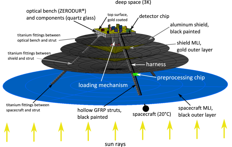
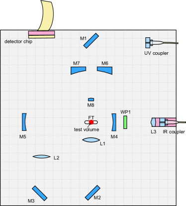
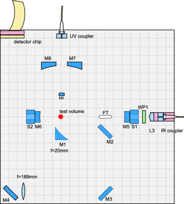
Figure 1 schematically illustrates the geometric mathematical model for a radiatively cooled instrument of MAQRO (Kaltenbaek et al., 2012a, b) as it was first analysed in (Hechenblaikner et al., 2014). Figure 2 shows the optical bench and the optical fields.
The disc at the bottom of Figure 1 represents the spacecraft MLI with an outer layer of black Kapton.
In the quantum experiments proposed in MAQRO, the central element is a dielectric nanosphere. Various methods for loading such particles into an optical trap in ultra-high-vacuum (UHV) conditions are being investigated. In Figure 1, this is referred to as loading mechanism. From the loading region, the particle is propelled towards the cavity mode via radiation pressure by an IR beam. Two additional IR beams, represented as IRtrans in Figure 2, are used to confine the region where the particle should be during the experiment. If the particle leaves that region, it scatters light that can be detected by a chip located on the optical bench, here called detector chip (Love et al., 2004). In this case, the particle has to be transported back into the region of interest along the cavity mode. The immediate environment of the position where the nanosphere is supposed to be located is referred to as test volume(Hechenblaikner et al., 2014). This test volume is modelled as a black body with and zero specific heat capacity ().
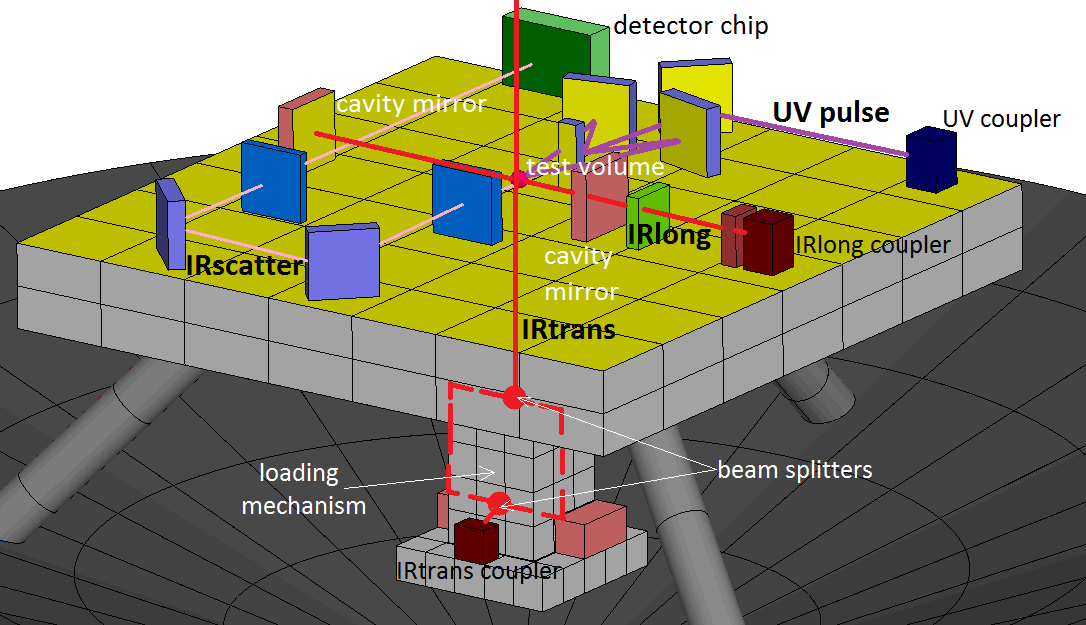
The central element on the optical bench is an asymmetric optical cavity with a cavity length of 97 mm consisting of two high-reflectivity spherical mirrors with radii of curvature of 75 mm and 30 mm. Two optical modes of IR light (1064 nm), represented as IRlong in Figure 2, are fed into the cavity from an IR fibre coupler. The two modes have orthogonal polarisation and are shifted in frequency with respect to each other by one free spectral range (FSR) of the cavity. One mode is used to trap the particle. The second mode can be used to either read out the particle position or to cavity-cool the center-of-mass motion of the trapped particle (Kiesel et al., 2013; Li et al., 2011; Horak et al., 1997). The beam waist size of the cavity mode is .
A combination of mirrors and lenses is used to image the trapping region onto a detector chip and to detect the light scattered from the nanosphere (IRscatter).
In addition to these optical elements for the cavity modes and the scattered light, the optical design also contains several reflective optical elements for UV light. These are intended to illustrate a possible way for the preparation of a macroscopic superposition via applying a short and well-focused UV beam to the trapping region. If light is scattered by the nanosphere, its wavefunction will be well localised. If no light is scattered, the particle will be in a quantum superposition of being located anywhere outside the region illuminated by the UV beam (Kaltenbaek et al., 2012a; Kaltenbaek, 2013). Alternative methods of preparing the quantum superposition are currently investigated.
Except for the optical dissipation of the cavity mirrors, our thermal simulations assume the optical fields to be turned off as in the case during wavefunction evolution between preparing and detecting the quantum state. Note, that this is a worst case estimation because during the time of wave-function expansion, strong sources of dissipation like the CMOS and preprocessing chips may actually be turned off.
For our simulation, we assumed the optical bench as well as the structural elements of the loading mechanism to be made of ZERODUR®, which is also used for the optical design in the LISA and LISA Pathfinder missions (McNamara et al., 2008). The upper surface of the bench is coated with gold in order to minimise radiative heat transfer to the test volume (Hechenblaikner et al., 2014). We assume the material of all optical elements on the optical bench to be fused silica and that these elements are bonded to the bench through hydroxide-catalysis bonding described in (Elliffe et al., 2005).
The struts support the optical bench and connect it to the spacecraft. Each of the three struts is made of a hollow GFRP tube filled with polyurethane foam in order to avoid radiative heat exchange between the internal walls of the strut (Hechenblaikner et al., 2014). A set of shields are modelled in order to prevent spacecraft heat radiation from reaching the bench as also seen in (Hawarden et al., 1992). These shields consist of an aluminium plate whose bottom side is covered with MLI consisting of 20 layers. The aluminium plate is black painted on its top side and gold coated on its lower side. The MLI is aluminised on its side to the shield and coated with a thin gold layer on its side to the spacecraft. The opening angles and relative distances are chosen to have the optimum values derived in Ref. (Hechenblaikner et al., 2014).
The boundary nodes for our simulation are deep space at 3 K and the spacecraft. For the constant internal temperature of the spacecraft we assume C. This value is representative for the constant internal temperature seen in various payloads. Components such as harness, optical fibres and the preprocessing chip were not geometrically modelled due to their small emitting areas, which makes their radiative influence on the bench temperatures negligible (Hechenblaikner et al., 2014).
For the radiative analysis, we used the Monte Carlo ray-tracing method to determine the radiative exchange factors between the different surfaces of the geometrical model. In the analysis of the radiative model, we use a fixed quantity of rays. These are propagated from various emitting surface elements to the test volume. We sample a fixed quantity of 10 000 rays propagating towards other instrument components. The radiative coupling between two model nodes and is calculated using equation 1 as described in (ITP Engines UK Ltd, 2010).
| (1) |
The Monte Carlo ray-tracing method is also used for the orbital cases to evaluate external heat loads on the instrument such as solar, albedo and Earth infrared heat (ITP Engines UK Ltd, 2010).
II.2 The thermal mathematical model and the energy equation
The conductive couplings between two nodes in the TMM can be calculated using equation 2 (see also Ref. (ITP Engines UK Ltd, 2010)).
| (2) |
The preprocessing chip, as described for instance in (Loose et al., 2005), is fixed below the first shield so that its dissipation does not directly affect the optical bench. The harness that connects the detector chip, the preprocessing chip and the spacecraft as Figure 1 schematically shows is assumed to consist of steel. For simplicity, the thermal properties of the chips are assumed to be the same as for quartz glass.
Based on the results of Ref. (Hechenblaikner et al., 2014), we neglected optical fibres in our model. They have little influence on the bench temperature due to their low heat conductivity. The spacecraft, the shields and the optical bench are assumed to be connected to the struts using titanium fittings. These are included in the thermal model as constant conductive couplings (Hechenblaikner et al., 2014).
The rate of heat flow between two different nodes and can be evaluated using the following equations for the radiative heat flow and the conductive heat flow , respectively:
| (3) |
| (4) |
For each single node , the energy equation can be evaluated using equation 5 (see Ref. (ITP Engines UK Ltd, 2010; Messerschmid and Fasoulas, 2011)):
|
|
(5) |
Here, the indices R, L and I refer to radiative, conductive and dissipation heat, respectively. S refers to solar heat, E to Earth albedo and infrared radiation from the Earth.
The dissipations considered in the TMM are: mW for the preprocessing chip, mW for the detector chip and mW of the cavity mirrors (Hechenblaikner et al., 2014). In our simulations, we assumed that all these sources of dissipation are continuously active. This represents a worst-case scenario because the dissipation will, in fact, be significantly less during the long free-fall times of the test particle (Kaltenbaek et al., 2012a).
The energy equation is evaluated for each node of the model and treated numerically as shown in (ITP Engines UK Ltd, 2010). An iterative and an inverse matrix solver are used for the steady state. As a plausibility check for our analysis, we compared the temperature predicted by these two methods for the test volume. The difference was at most K. For the transient cases, we used the Crank-Nicolson methodCrank and Nicolson (1947) and the backward differentiation formula based on the Gear formalismShampine and Gear (1979).
II.3 Transfer-function analysis
The amount of solar radiation the spacecraft experiences varies in the course of HEO orbit. This can lead to small oscillations of the internal temperature of the spacecraft. We can investigate the influence of such oscillations on the instrument temperature using a transfer-function analysis in steady state. For that purpose, the energy equation is linearised and transformed through Laplace transformation from the time to the frequency domain as described for instance in (Altenburg and Burkhardt, 2008). Using this approach, we can calculate the relation between the temperature oscillations of the spacecraft and resulting changes in temperature at various instrument components. Due to the linearisation, only small temperature variations of the spacecraft can be considered.
This relation, also referred to as gain, is calculated with the help of the software TransFAST developed by the company Airbus Defence & Space (ADS, formerly Astrium GmbH) (Altenburg and Burkhardt, 2010).
III Results and discussion
Because the temperature difference between spacecraft and the optical bench is around 266 K, the struts needed to be highly discretised. Figure 3 shows the temperature distribution along an individual strut depending on the node mesh.
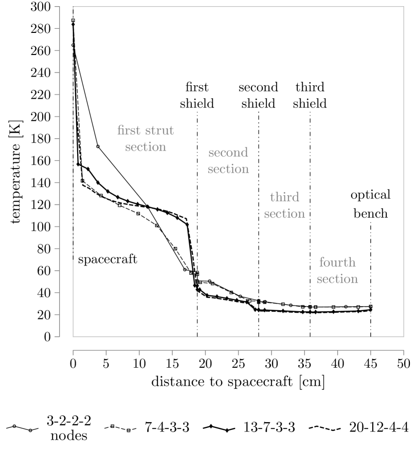
In our thermal analysis, we optimised our mesh to 13 axial nodes for the first strut section, 7 axial nodes for the second section and 3 nodes for the third section. Using even finer meshes is unnecessary because it results in the same temperature distribution for the regions close to the optical bench, as apparent from Fig. 3
It can be seen that 13 axial nodes for the first strut section, 7 axial nodes for the second and 3 nodes for the third and fourth sections are adequate for detailing the temperature attenuation along the strut.
It can be shown that the maximum temperature difference along the surface of each aluminium shield was about K and, along the surface of the optical bench, it was about K(Pilan Zanoni, 2014). For this reason, we can assume the shields and the optical bench to have uniformly distributed temperatures. The same analysis showed that the test volume has a steady-state temperature of about K and the optical bench about 24.7 K. Due to the minimisation of numerical averaging effects, a reduction in the temperature of the test volume of about 2.4 K is observed in comparison with the results obtained in (Hechenblaikner et al., 2014).
III.1 Heat-flow analysis
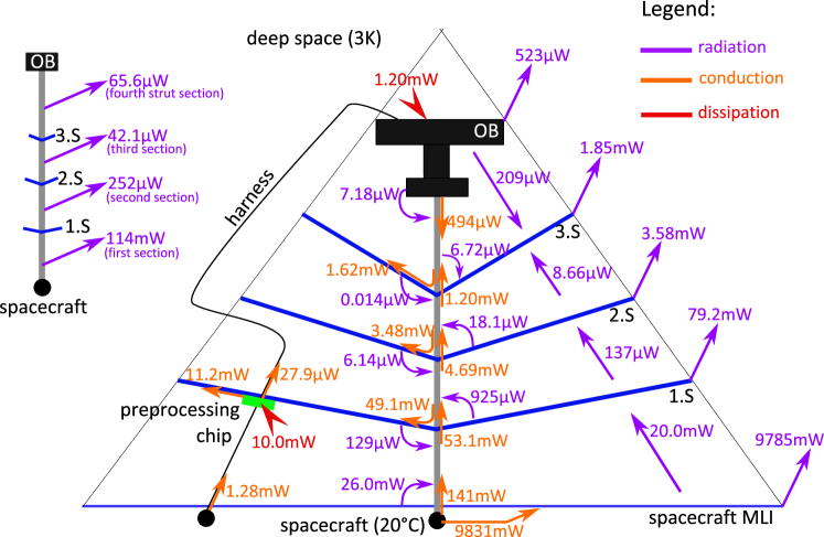
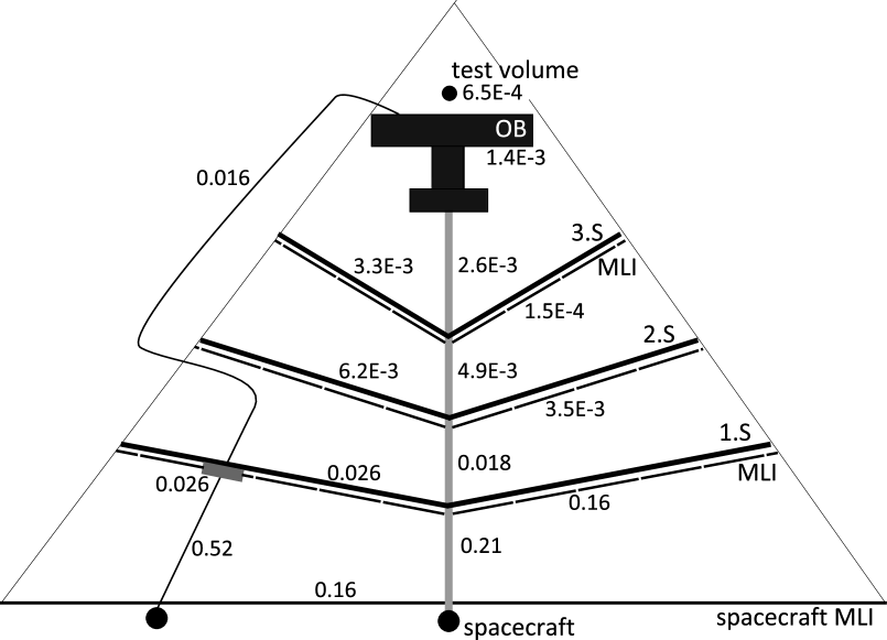
We performed a heat-flow analysis for the entire MAQRO instrument in steady state in order to quantify the heat transfer between the different instrument components and to better assess the temperature results. Figure 4 describes the results of this analysis.
The heat flow in the instrument is partially due to the temperature difference between the spacecraft (C) and deep space (3 K) and partially due to the dissipation sources represented as red arrows in Figure 4. These sources are divided into the dissipation of the preprocessing chip and the dissipation of the bench, which comprises the dissipations of the detector chip and of the cavity mirrors. Radiative heat flow is represented in purple, conductive heat flow in orange.
The harness is represented as a loose black line in Figure 4. The schematic representation shows the three shields (1.S, 2.S and 3.S), the optical bench (OB) and the spacecraft MLI (S/C MLI). For the sake of simplicity, the three struts are represented as a single gray tube and the radiative flow of each strut section to deep space is detailed in a separate illustration on the left-hand side of Figure 4. The thin black lines form a triangle illustrating the line of sight between the spacecraft and the optical bench. The entire optical bench must be inside that triangle in order to avoid receiving direct radiation from the spacecraft MLI.
The dominant part (9785 mW) of the heat energy of the spacecraft surface is radiated to deep space directly from the spacecraft MLI. To a smaller extent, energy is radiated to deep space from the shields. Still, this plays an important role for the passive cooling system. Firstly, the shields prevent the massive amount of energy from the spacecraft from reaching the optical bench by blocking the direct line of sight between bench and spacecraft. Secondly, they act as radiators as they receive energy through conduction from the struts and emit this heat to deep space via radiation.
Figure 4 also demonstrates the advantage of positioning the preprocessing chip below the first shield. The 10 mW dissipation is conducted to the first shield and is emitted from there to deep space. This prevents this dissipation heat from reaching the optical bench. Nevertheless, a very small part of it still flows through the harness. This assumption is based on an idealised connection between the preprocessing chip and the first shield, which led to a conductive coupling of around . For comparison, the coupling between harness and preprocessing chip is .
A sensitivity analysis showed that the temperature of the test volume increases to around 20 K if the dissipation of the detector chip increases from 1 mW to 12 mW (Pilan Zanoni, 2014).
The dissipation of electronic and optical elements on the optical bench results in the third shield having a lower temperature (22.4 K) than the optical bench itself (24.7 K). Although virtually no radiative heat from the other shields reaches the third one, this shield has an important function in cooling the optical bench by receiving part of the heat from the bench and radiating it to deep space. Therefore, the removal of the third shield would cause a considerable increase of the temperature of the test volume as observed in (Hechenblaikner et al., 2014) for a configuration with only two shields.
The first strut section removes a great part of the energy radiatively to deep space. However, the amount of radiated heat from the struts to deep space diminishes along the strut because of the thermal attenuation induced by the shields. Note that, as consequence of the dissipation on the optical bench, the fourth section radiates slightly more heat to deep space than the third section.
Figure 4 illustrates that the configuration of the shields is well-optimised for passively cooling the optical bench because the heat flow on the path from the spacecraft to the optical bench is strongly attenuated. While increasing the number of shields would yield only a very slight increase in that attenuation (Hechenblaikner et al., 2014), it would significantly increase the complexity of the instrument.
One can also conclude from the heat-flow diagram that the heat flow in the instrument is consistent with the temperatures shown in Figure 3. For instance, the low temperature obtained for the test volume and the optical bench is due to the fact that the amount of heat that circulates in the bench is much smaller than the amount that circulates in the shields and the struts.
III.2 Transfer-function analysis
We performed a transfer-function analysis in order to investigate the effect of temperature oscillations of the spacecraft on the temperatures of the instrument. We considered temperature variations with oscillation frequencies in the spectral range between to . This corresponds to an oscillation period between 10 s and 11.6 days, respectively. These periods cover the time scale of the optomechanical experiments considered for MAQRO. For such measurements, the temperature of the optical bench should be kept constant over a period of 100 s for a single measurement and from five to ten days for a full measurement series (Kaltenbaek et al., 2012a). Figure 5 shows the calculated gains of each instrument component.
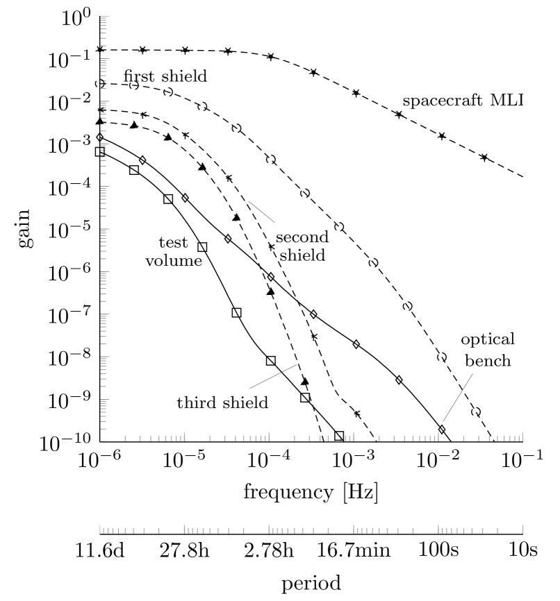
The gain is defined as the differential temperature at the output, which can be any instrument component under test, divided by the differential temperature at the input, such as fluctuations in the spacecraft. Thermal disturbances are transferred on a much slower time scale compared, for example, to electrical oscillations. Consequently, the inertia of thermal fluctuations, especially at low frequencies, lead to larger thermal gains.
Figure 6 shows a detailed analysis of gains across the instrument for a low frequency of Hz. We chose to depict this analysis for that frequency because it induces the largest gains. The gain for each strut section corresponds to the average of the three struts belonging to the same section.
Instrument components that are conductively linked to the spacecraft, like the first section of the struts and the first section of the harness, have the highest gains. For components radiatively coupled to the spacecraft, the gains are smaller. Clearly, components that are directly connected with the source of oscillation, like the spacecraft MLI and the MLI of the first shield, are strongly influenced by the temperature variations. This results in higher gains than for components far from the source of oscillation.
We can conclude from the results shown in Figure 6 that temperature oscillations of the spacecraft have only very little effect on the temperature of the optical bench. For the optical bench, the gain is . That means, a temperature change of the spacecraft of 5 K over 11.6 days only results in a change of less than 0.01 K in the temperature of the optical bench. Still, even small temperature variations can have consequences on the fractional frequency instability of the cavity on the optical bench of MAQRO. We define this frequency instability as . Consider that the coefficient of thermal expansion (CTE) for ZERODUR® is around at 30 K, that the cavity length is about 100 mm and that the temperature fluctuations are attenuated by a factor of for an oscillation of 5 K over a period of 100 s. In this case, the relative change in cavity length will be . This is comparable to the best fractional frequency instabilities achievable in ground-based cavity designs today, where the cavity is isolated from temperature fluctuations outside the vacuum system as well as possible (Numata et al., 2004; Notcutt et al., 2006; Amairi et al., 2013).
Because of the fact that the radiative terms are linearised for the solution of the energy equation, the results obtained for the temperature gains are only accurate for small variations. Nevertheless, it was shown with a sensitivity analysis performed in (Pilan Zanoni, 2014) with the physically representative non-linear thermal model that the temperatures of the test volume and of the optical bench remain small for a wide range of input temperatures. Remarkably, even large changes of the spacecraft temperature only lead to small changes in the temperature of the test volume. For example, an increase of the temperature, say, from K to K induces only a temperature increase in the optical bench from K to K and in the test volume from K to K. Some of the input temperatures are not applicable to a real spacecraft and were only analysed for the purpose of the sensitivity analysis.
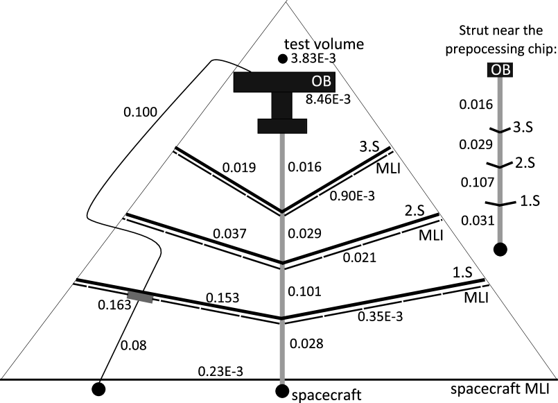
We also investigated the effect of oscillations of the dissipation in the preprocessing chip. These may, for example, result from operating a detector chip having a CCD sensor at varying frame rates. The gains [in K/mW] are now defined as the differential temperature at different components [in K] divided by the differential power at the input [in mW], which is now the dissipation of the preprocessing chip. These gains are presented in Figure 7. Although electric components exhibit much higher oscillation frequencies in reality, this investigation is restrained to a very low frequency of Hz which represents a worst-case scenario for thermal oscillations.
The aluminium plate of the first shield and both harness sections present the highest gains because they are directly connected to the preprocessing chip via thermal conduction. The MLI of the first shield has a very low gain because it is neither coupled conductively nor radiatively with the preprocessing chip.
Because of the fact that the preprocessing chip is mounted below the first shield near one of the struts, the gain of this strut is higher than the gains of the other ones. However, the gains of the struts from the third section on are approximately the same as the dissipation of the preprocessing chip is less dominant.
The heat oscillation of the preprocessing chip at a frequency of Hz induces a temperature variation of the optical bench of around . As a result, the temperature of the optical bench would increase by less than 0.01 K if the dissipation increased by 1 mW. This leads to a frequency instability of the optical cavity similar to that derived in the case of fluctuations of the spacecraft temperature.
III.3 Optimizing the thermal properties of the optical bench
For the present study, we optimised the optical bench for MAQRO with respect to the temperature of the test volume by using reflective rather than refractive optics for the imaging design.
Figure 8 schematically shows that a combination of a parabolic mirror and several flat mirrors is now used to image the trapping region onto a detector chip rather than lenses. The camera to be used was developed for the James Webb Space Telescope (JWST) (Love et al., 2004; Loose et al., 2005).
In this optimised design, the mirrors are bonded to a ZERODUR® block with a central hole, which we refer to as spacer. Each spacer is in turn bonded to the optical bench. A cavity design of this type allows for maximum optical access to the nanosphere trapped in the cavity mode and it is optimal for passive cooling of the test volume.
Another design change is that the nanospheres are now loaded into the cavity mode at a position approximately 24.25 mm from the mirror closest to the IR coupler, at of the cavity length.
In terms of the radiative influence of the various bench components on the test volume, the most significant difference between both designs is the substitution of the lens L1 with the parabolic mirror M1 near the test volume. The advantage of the mirror is that it can be coated with gold, which minimises the thermal radiation towards the test volume. The reflecting area of the mirror is larger by a factor than the original lens to keep the numerical aperture of the imaging system constant.
We calculated a temperature of 13.9 K for the test volume considering the preliminary bench with the lens L1. For the optimised bench using reflective optics, this temperature decreases to 11.2 K assuming that the mirror M1 is finished with gold. However, the temperature of the test volume temperature could rise to 14.3 K if the mirror M1 is not coated. This is higher than the temperature for the preliminary design as a consequence of the adjustment of the mirror reflecting area.
III.4 Orbital cases
We analysed the transient thermal behavior of the instrument for two types of orbit: an orbit around the Lagrangian point L2 with respect to Sun & Earth and a quasi-stationary highly elliptical Earth orbit. The first orbit is evaluated using a cool-down analysis of the whole instrument, whereas the latter intends to indicate operational constraints of a possible space mission in an Earth orbit.
The scenario with the orbit around L2 assumes that the whole instrument has a starting temperature of C and is left to cool down by radiating to deep space. The orbit is considered to be sun oriented if the normal vector to the spacecraft surface points towards the sun throughout the orbit. This way the instrument can be accommodated on the sun shaded part of the spacecraft and does not receive any direct solar radiation. Because of the fact that the L2 point lies on the line through the sun and the Earth beyond the Earth at a distance of 1.5 million km, the optical bench is also completely shielded against direct Earth radiation.
For the the highly elliptical Earth orbit, we choose the following orbital parameters for the thermal analysis: altitude at apogee = 600 000 km, altitude at perigee = 600 km, inclination , argument of periapsis = ; right ascension of the ascending node = . In this case the orbital period is around 19.6 days. Using these values the instrument has a very high view factor to the Earth at perigee and a low view factor to the Earth at apogee.
We assumed an average sun radiation flux of 1369 at 1 AU, an average Earth albedo reflectance of 0.3 and a uniform Earth infrared emissivity of 1 at 257 K. The criterion for a quasi-stationary highly elliptical orbit is fulfilled if the temperatures of all nodes must periodically recur at a predetermined orbital position after successive cycles.
III.4.1 Thermal-analysis results of the orbit around L2
Figure 9 shows the results of the thermal analysis considering an L2 scenario. The evolution of the dropping temperature of the passively cooled instrument has a fourth-degree polynomial dependence on time. While the cooling progresses quickly in the beginning, it then converges slowly towards the steady state at later times. This is consistent with the fact that deep space acts as the sole heat sink of the instrument.
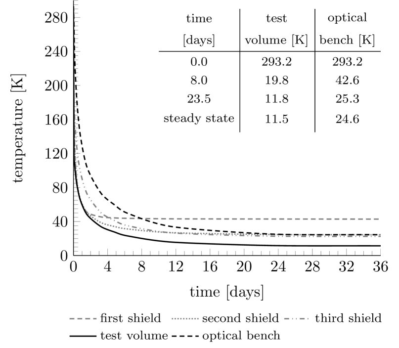
Among the instrument components investigated, the first shield is the quickest to reach the steady state. It only takes around 3 days because that component has the highest steady-state temperature compared to other components. The last component to reach the steady state is the optical bench as it has a low steady-state temperature and a high heat capacity. It takes around 24 days for the bench to achieve a temperature less than 25 K.
The temperature of the test volume drops at the start of the cooling because it has a high view factor to deep space and zero heat capacity. It takes around 8 days for the test volume to cool down below 20 K and another 16 days for an additional temperature decrease of 8 K.
III.4.2 Thermal-analysis results of the quasi-stationary highly elliptical orbit
Figure 10 depicts the thermal behavior of the instrument in a quasi-stationary highly elliptical orbit. The temperature of an instrument component is the average of the temperatures of its nodes.
Our simulations showed that no solar heat flow was directly incident on any node of the instrument. This confirms the sun orientation of the spacecraft.
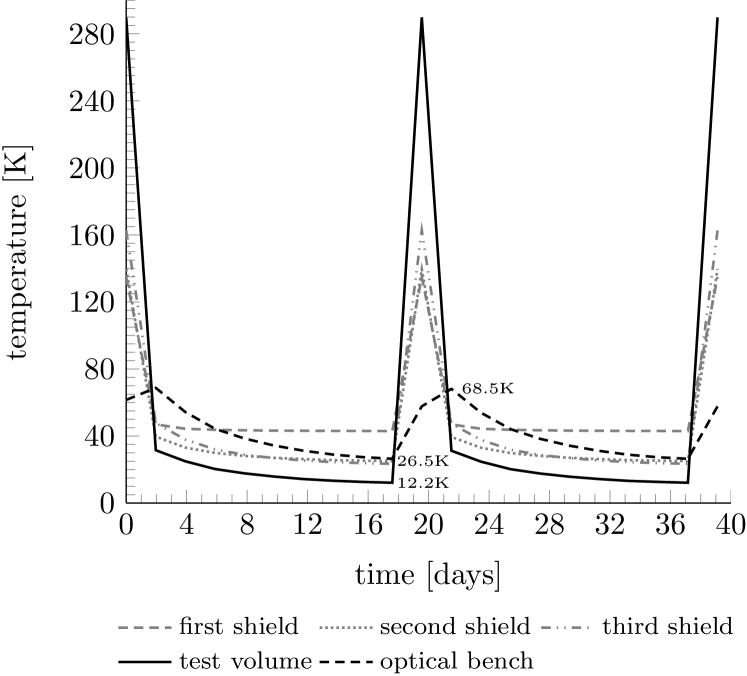
The temperatures of the instrument components reach their peaks right after the perigee. After that, the instrument is cooled down while traveling towards the apogee, where the Earth thermal influence diminishes to a very large extent. The temperatures drop rapidly at first and then slowly converge towards steady state during the cooling phase before the next peak.
The temperature of the optical bench ranges between 26 K and 69 K along the whole orbit. The maximum temperature change rate is around 10 K/day. Because of the fact that the bench possesses a high heat capacity at low temperatures, its temperature change is smaller than for the other instrument components.
It takes around seven days for the test volume to cool below 20 K after the point when it passes through perigee. Its temperature reaches 12.2 K eleven days later. As the test volume is modelled as having zero heat capacity, its temperature increases from 12.2 K to 290 K within seven hours before reaching the perigee. However, this is also the reason why its temperature decreases suddenly after leaving the perigee.
III.4.3 Discussion of the orbital cases
The starting temperatures of the whole instrument for the L2 scenario was C. From this starting point, it takes about eight days for the test volume to reach temperatures below the technical requirements of MAQRO, i.e., below 20 K. For the highly elliptical orbit, we took the quasi-stationary temperatures in the instrument at perigee as the starting condition. It then takes about seven days for the test volume to cool down below 20 K. The quantum experiments must be interrupted each eleven days in this orbit due to the higher heat loads at perigee. In contrast, the experiments can be performed without interruptions for the L2 scenario.
In principle, a highly elliptical orbit scenario could offer more flexibility in the mission planning as the instrument can be flown on a satellite for Earth observation. Nevertheless, the bench is periodically exposed to temperature changes due to the periodical heat loads, which may cause, e. g., misalignment of the bench components, high thermal stressGwo (2003) or even structural changes such as loss of the bonding force between interfaces due to hysteresis effects caused by thermal cycles. In addition, the heat load coming from the Earth is not uniformly distributed across the instrument, which induces an uneven temperature distribution.
Several concepts of shielding the instrument against Earth radiation were analysed in order to reduce the effects of Earth radiation on the instrument. These analyses showed that the measurements performed by MAQRO are constrained to only 2 days even for the best-case scenario investigated (Pilan Zanoni, 2014). The extra shields do not only block a part of the Earth radiation at perigee, but also block a part of the view factor of the instrument to deep space at apogee. Therefore, the advantage gained by shielding the instrument against the hot radiation from Earth is largely offset by the reduced efficiency of cooling via thermal radiation to deep space and the additional thermal photons received from the extra shields.
III.4.4 Thermal results considering an SiC bench for the L2 scenario
At the cryogenic temperatures expected for the optical bench in MAQRO, ZERODUR® may not be the optimal choice of material. In particular, at temperatures below 30 K, Silicon Carbide (SiC) has a significantly lower (Roose and Heltzel, 2013). For that reason, we also performed a thermal analysis for an optical bench made of SiC in the case of an orbit around the Sun-Earth Lagrangian point L2.
The results showed that the test volume cooled down significantly faster with an SiC bench. It reached a temperature below 20 K within 3 days (for the ZERODUR® bench: 8 days). The optical bench reached a temperature of 25 K in 5 days (for the ZERODUR® bench: 24 days). This is due to the smaller heat capacity of SiC compared to ZERODUR®. By extrapolating these results to the case of a highly elliptical orbit, one can expect an extension of the time period during which the thermal requirements of MAQRO are fulfilled by around 5 days per orbital cycle (Pilan Zanoni, 2014).
Although SiC has a much higher thermal conductivity than ZERODUR®, the steady-state temperatures of the test volume for the ZERODUR® bench (11.4 K) and for the SiC bench (11.2 K) are nearly identical. This is consistent with the fact that the heat that reaches the optical bench is rather low (see section III.1).
III.5 Further concept improvements
Here, we discuss the potential for improvements in the passive-cooling design in order to further optimise the steady-state temperatures of the test volume and the optical bench.
III.5.1 Configuration of the MLI on the shields
From the heat-flow diagram in Figure 4, one can see that the radiative heat transfer on the third shield is comparatively low. Moreover, the oscillations of the spacecraft temperature and the variations of the dissipation of the preprocessing chip are strongly attenuated on the path from the oscillation source to the MLI of the third shield (see Figure 7). For these reasons, we considered scenarios where the MLI was removed on one or more shields. We present the corresponding results in Table 1.
| Analysis | test | optical | shield | |
|---|---|---|---|---|
| description | volume | bench | plate | |
| [K] | [K] | [K] | ||
| Base configuration | 11.6 | 24.5 | 22.3 | |
| shield black painted | } | 11.6 | 24.5 | 22.4 |
| and black MLI outer layer | ||||
| MLI removed | } | 11.6 | 24.5 | 22.4 |
| from shield | ||||
| MLI removed | } | 11.8 | 24.6 | 22.9 |
| from and shields | ||||
| MLI removed | 13.0 | 27.5 | 26.4 | |
| from , | ||||
| and shields |
From these results, one can see that the presence or absence of the MLI on the third shield effectively has no influence on the steady-state temperatures of the test volume and the optical bench. Therefore, the shield design can be simplified by removing the MLI from the third shield. The aluminium plate of the third shield must be retained because it is essential for the radiation of heat to deep space and acts as a heat sink for the optical bench (see Figure 4).
Slight changes in the temperatures of the test volume and of the optical bench were seen by additionally removing the MLI from the second shield. Despite that, the MLI on the second shield should not be removed because it has a significantly higher gain with respect to variations in the dissipation heat of the preprocessing chip (0.021 K/mW) than the MLI on the third shield ().
Because of the fact that the heat flow on the MLI of the first shield is comparatively high, its removal would cause a significant change in the temperatures of the test volume and the optical bench. This renders the MLI of the first shield essential for passive cooling.
| diameter of | MLI | test | optical | outer layer of | ||||
|---|---|---|---|---|---|---|---|---|
| shield | outer | volume | bench | shield MLI | ||||
| [m] | layer | [K] | [K] | [K] | ||||
| 0.9 | gold | 11.4 | 24.5 | 123.4 | ||||
| 2.4 | gold | 9.7 | 18.9 | 520.5 | ||||
| 2.4 | black | 9.7 | 19.1 | 370.7 |
III.5.2 Extension of the shields
We showed in section III.1 that the shields act as radiators in removing heat coming from the struts and from the spacecraft to deep space. Is it possible to improve this effect by using larger shields? We tried to address this issue by investigating a design with extended shields. In particular, we analysed a design where the shields are just large enough to still fit into a Soyuz-Fregat fairing with a diameter of 2.8 m. The configuration of the struts and the dimensions of the interface with the spacecraft were the same as described in the previous sections. In this modified configuration, the first shield is extended beyond the spacecraft boundary and, therefore, this shield receives direct solar radiation in a sun-oriented orbit. We used the Monte Carlo method for modeling the solar radiation and we present the results of this analysis in Table 2.
Our results show that extending the shields leads to a reduction of the temperature of the test volume and that of the optical bench by 1.7 K and 5.5 K, respectively. In contrast to that, the temperature of the outer layer of the MLI of the first shield increases by at least 247 K because of the exposure of the shield to solar radiation.
The outer layer of the MLI has a strong influence on its temperature as a difference of 150 K between the cases with gold and black Kapton was observed. As and , the gold layer absorbs much more sun radiation than it itself can radiate through infrared light. Therefore, the outer layer of the MLI must not be coated with gold in order to avoid thermal degradation.
III.5.3 Heat-flow analysis for the optical bench
| gold | temperature [K] | radiated heat [W] | ||||||
| area | test | optical | ||||||
| [] | volume | bench | gold area | area | ||||
| 0 | 18.4 | 23.1 | - | 447 | ||||
| 73.5 | 12.4 | 23.3 | 2.17 | 385 | ||||
| 204 | 11.1 | 23.7 | 6.70 | 242 | ||||
| 400 | 11.1 | 24.4 | 14.1 | - | ||||
To probe for further possible design improvements, we analysed the heat transfer in the optical bench The corresponding results are shown in Figure 11. To this end, we divided the optical bench into its lower and lateral surfaces, the loading mechanism (LM) and the optical components. The optical components radiate a large part of heat to deep space because the dissipation on the optical bench is largely caused by the detector chip and the cavity mirrors. The top surface of the optical bench radiates to deep space to a significantly smaller extent because of its gold finishing.
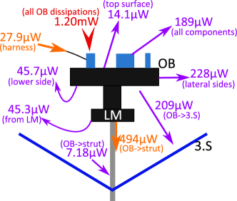
An investigation of the gold finishing of the top surface of the bench was performed in order to maximise the radiation to deep space. This was done by partially coating the upper surface. The area near the test volume was finished with gold (), where the test volume position is located above the center of this area. The remaining area of the bench has . Table 3 shows the results.
Increasing the gold area reduces the radiation of the top surface of the bench to deep space. Consequently, the test volume receives less radiation and its temperature is lower.
By increasing the area not coated with gold, the top surface of the optical bench can radiate significantly more to deep space, reducing the overall temperature of the optical bench. On the down side, this radiation increases the temperature of the test volume.
More detailed investigations of the technical requirements of MAQRO, in particular the decohering effects of a non-isotropic distribution of thermal radiation in the immediate environment of the nanosphere, should allow determining the ideal ratio between the gold-coated and uncoated areas of the optical bench in the future.
IV Conclusions
We investigated several aspects of the performance and the design of a radiatively cooled system for quantum optomechanical experiments in the context of the proposed future space mission MAQRO. This instrument consists of an optical bench externally mounted to the spacecraft surface with a set of struts and shielded against direct heat exchange with the hot spacecraft and the sun. The optical bench is used for performing quantum measurements at cryogenic temperatures and microgravity conditions in deep space. A geometric and a thermal mathematical model of the instrument are implemented with the aid of numerical tools such as ESATAN-TMS and TransFAST.
A heat-flow analysis of the entire instrument shows that the shields not only block the spacecraft radiation, but also act as radiators in receiving the heat from the instrument through the struts and emitting it to deep space. Our analysis shows that the configuration of the instrument consisting of three shields is thermally well optimised. It also showed that positioning the preprocessing chip for optical imaging below the first shield diverted the resulting dissipation heat into the shield rather than into the optical bench.
A transfer-function analysis showed that the shield structure strongly attenuates variations of the spacecraft temperature as well as of the dissipation of the preprocessing chip. For example, a change of the spacecraft temperature by 5 K results only in a change of less than 0.01 K in the temperature of the optical bench. Considering a fluctuation period of 100 s, the fractional frequency instability of the cavity on the optical bench of MAQRO is around , which is comparable to the best values achieved in ground-based cavity designs.
By a simple modification of the imaging optics on the optical bench (replacing a lens with a gold-coated, parabolic mirror) we achieved a reduction from 13.9 K to 11.2 K for the steady-state temperature of the test volume.
In an analysis of various orbital cases, we showed that it takes about 8 days for the test volume and 24 days for the optical bench to passively cool down to less than 20 K in an orbit around L2 considering an initial temperature of C for the entire instrument. These times can be reduced significantly by using SiC instead of ZERODUR® for the material of the optical bench. For a highly elliptical orbit with an orbital period of about 20 days, the time the instrument needs to cool down below the technical requirements of MAQRO would significantly restrict the time for experiments to 11 days for each period in the case of a ZERODUR® bench. This limitation is more relaxed for an SiC bench.
A reduction from 11.4 K to 9.7 K in the steady-state temperature of the test volume and from 24.5 K to 19.1 K in that of the optical bench can be obtained by extending the shields.
Acknowledgements
We acknowledge support from the Austrian Research Promotion Agency (FFG, project no. 3589434).
References
- Romero-Isart et al. (2011) O. Romero-Isart, A. C. Pflanzer, F. Blaser, R. Kaltenbaek, N. Kiesel, M. Aspelmeyer, and J. I. Cirac, Phys. Rev. Lett. 107, 020405 (2011).
- Kaltenbaek et al. (2012a) R. Kaltenbaek, G. Hechenblaikner, N. Kiesel, O. Romero-Isart, K. C. Schwab, U. Johann, and M. Aspelmeyer, Experimental Astronomy 34, 123 (2012a).
- Swinyard and Nakagawa (2009) B. Swinyard and T. Nakagawa, Experimental Astronomy 23, 193 (2009).
- Hawarden et al. (1992) T. G. Hawarden, R. O. Cummings, C. M. Telesco, and H. A. T. Jr, Space Science Review 61, 113 (1992).
- Hawarden et al. (1996) T. G. Hawarden, R. Crane, H. A. Thronson Jr, A. J. Penny, A. H. Orlowska, and T. W. Bradshaw, in Infrared and Submillimeter Space Missions in the Coming Decade (Springer, 1996) pp. 45–56.
- Lightsey et al. (2012) P. A. Lightsey, C. Atkinson, M. Clampin, and L. D. Feinberg, Optical Engineering 51, 011003 (2012).
- de Bruijne (2012) J. de Bruijne, Astrophysics and Space Science 341, 31 (2012).
- Urgoiti and Migliorero (2005) E. Urgoiti and G. Migliorero, in 11th European Space Mechanisms and Tribology Symposium, ESMATS 2005, Vol. 591 (2005) pp. 163–170.
- Pilbratt et al. (2010) G. Pilbratt, J. Riedinger, T. Passvogel, G. Crone, D. Doyle, U. Gageur, A. Heras, C. Jewell, L. Metcalfe, S. Ott, et al., Astronomy & Astrophysics 518, L1 (2010).
- Tauber et al. (2010) J. A. Tauber, N. Mandolesi, J.-L. Puget, et al., Astronomy & Astrophysics 520, A1 (2010).
- Oran and Naumann (1977) W. Oran and R. Naumann, NASA STI/Recon Technical Report N 77, 31222 (1977).
- Kaltenbaek et al. (2012b) R. Kaltenbaek, G. Hechenblaikner, N. Kiesel, F. Blaser, S. Gröblacher, S. Hofer, W. Vanner, M R Wieczorek, K. C. Schwab, U. Johann, and M. Aspelmeyer, Macroscopic quantum experiments in space using massive mechanical resonators, Tech. Rep. (Study conducted under contract with the European Space Agency, Po P5401000400, 2011–2012).
- Hechenblaikner et al. (2014) G. Hechenblaikner, F. Hufgard, J. Burkhardt, N. Kiesel, U. Johann, M. Aspelmeyer, and R. Kaltenbaek, New Journal of Physics 16, 013058 (2014).
- Chang et al. (2010) D. E. Chang, C. A. Regal, S. B. Papp, D. J. Wilson, J. Ye, O. Painter, H. J. Kimble, and P. Zoller, Proceedings of the National Academy of Sciences of the United States of America 107, 1005 (2010).
- Romero-Isart et al. (2010) O. Romero-Isart, M. L. Juan, R. Quidant, and J. I. Cirac, New J. Phys. 12, 033015 (2010).
- Barker and Shneider (2010) P. F. Barker and M. N. Shneider, Phys. Rev. A 81, 023826 (2010).
- Bassi et al. (2013) A. Bassi, K. Lochan, S. Satin, T. P. Singh, and H. Ulbricht, Rev. Mod. Phys. 85, 471 (2013).
- Hackermüller et al. (2004) L. Hackermüller, K. Hornberger, B. Brezger, A. Zeilinger, and M. Arndt, Nature 427, 711 (2004).
- Hackermüller et al. (2003) L. Hackermüller, K. Hornberger, B. Brezger, A. Zeilinger, and M. Arndt, Appl. Phys. B 77, 781 (2003).
- Romero-Isart (2011) O. Romero-Isart, Phys. Rev. A 84, 052121 (2011).
- ITP Engines UK Ltd (2010) ITP Engines UK Ltd, ESATAN-TMS thermal engineering manual, Tech. Rep. (available at www.esatan-tms.com, 2010).
- Love et al. (2004) P. J. Love, A. W. Hoffman, N. A. Lum, K. J. Ando, W. D. Ritchie, N. J. Therrien, A. G. Toth, and R. S. Holcombe, Proc. of SPIE 5499, 86 (2004).
- Kiesel et al. (2013) N. Kiesel, F. Blaser, U. Delic, D. Grass, R. Kaltenbaek, and M. Aspelmeyer, Proceedings of the National Academy of Sciences of the United States of America 110, 14180 (2013).
- Li et al. (2011) T. Li, S. Kheifets, and M. G. Raizen, Nature Physics 7, 527 (2011).
- Horak et al. (1997) P. Horak, G. Hechenblaikner, K. M. Gheri, H. Stecher, and H. Ritsch, Physical review letters 79, 4974 (1997).
- Kaltenbaek (2013) R. Kaltenbaek, in Optical Trapping and Optical Micromanipulation X, Vol. 8810 (2013) p. 88100B, arXiv:1307.7021 [quant-ph] .
- McNamara et al. (2008) P. McNamara, S. Vitale, K. Danzmann, and on behalf of the LISA Pathfinder Science Working Team, Classical and Quantum Gravity 25, 114034 (2008).
- Elliffe et al. (2005) E. J. Elliffe, J. Bogenstahl, A. Deshpande, J. Hough, C. Killow, S. Reid, D. Robertson, S. Rowan, H. Ward, and G. Cagnoli, Classical and quantum gravity 22, 257 (2005).
- Loose et al. (2005) M. Loose, J. Beletic, J. Blackwell, J. Garnett, S. Wong, D. Hall, S. Jacobson, M. Rieke, and G. Winters, in Optics & Photonics (International Society for Optics and Photonics, 2005) pp. 59040V–59040V.
- Messerschmid and Fasoulas (2011) E. Messerschmid and S. Fasoulas, in Raumfahrtsysteme (Springer Berlin Heidelberg, 2011) pp. 333–370.
- Crank and Nicolson (1947) J. Crank and P. Nicolson, Math. Proc. Camb. Philos. Soc. 43, 50 (1947).
- Shampine and Gear (1979) L. F. Shampine and C. W. Gear, SIAM Review 21, 1 (1979).
- Altenburg and Burkhardt (2008) M. Altenburg and J. Burkhardt, Application of Linear Control Methods to Satellite Thermal Analysis, Tech. Rep. (ICES 2008-01-2076, San Francisco, 2008).
- Altenburg and Burkhardt (2010) M. Altenburg and J. Burkhardt, in 24th European Workshop on Thermal and ECLS Software (ESTEC, Noordwijk, The Netherlands, 2010).
- Pilan Zanoni (2014) A. Pilan Zanoni, Thermal Analysis and System Concept Improvements of the MAQRO Experiment for Measuring of Quantum Effects, Master’s thesis, TU Dresden and Airbus Defence & Space (2014).
- Numata et al. (2004) K. Numata, A. Kemery, and J. Camp, Physical Review Letters 93, 250602 (2004).
- Notcutt et al. (2006) M. Notcutt, L.-S. Ma, A. D. Ludlow, S. M. Foreman, J. Ye, and J. L. Hall, Physical Review A 73, 031804 (2006).
- Amairi et al. (2013) S. Amairi, T. Legero, T. Kessler, U. Sterr, J. B. Wübbena, O. Mandel, and P. O. Schmidt, Applied Physics B 113, 233 (2013).
- Gwo (2003) D. Gwo, “Hydroxide-catalyzed bonding,” (2003), uS Patent 6,548,176.
- Roose and Heltzel (2013) S. Roose and S. Heltzel, High-precision measurements of the thermal expansion at cryogenic temperature on stable materials, Tech. Rep. (Physikalisch-Technische Bundesanstalt (PTB), 2013).