,
Enhanced light emission from Carbon Nanotubes integrated in silicon micro-resonator
Abstract
Single-wall carbon nanotube are considered a fascinating nanomaterial for photonic applications and are especially promising for efficient light emitter in the telecommunication wavelength range. Furthermore, their hybrid integration with silicon photonic structures makes them an ideal platform to explore the carbon nanotube instrinsic properties. Here we report on the strong photoluminescence enhancement from carbon nanotubes integrated in silicon ring resonator circuit under two pumping configurations: surface-illuminated pumping at 735 nm and collinear pumping at 1.26 m. Extremely efficient rejection of the non-resonant photoluminescence was obtained. In the collinear approach, an emission efficiency enhancement by a factor of 26 has been demonstrated in comparison with classical pumping scheme. This demonstration pave the way for the development of integrated light source in silicon based on carbon nanotubes.
1 Introduction
Carbon Nanotube photonics is an emerging field where researchers look for their potential application in the framework of on-chip optical communications. Several elementary building blocks are required to achieve an optical link. Such a circuit should embed light emitters, optical modulators and photodetectors coupled to an optical channel, in order to generate, propagate and transmit informations encoded on light directly on a chip. Thanks to their exceptional intrinsic optical properties[1, 2, 3], single-walled carbon nanotubes (SWNT) have the potential for building light emitting devices on silicon. Indeed, optical gain was demonstrated in polymer-wrapped SWNT[4], and Stark effect was observed in suspended SWNT[5].
In this field of nanotube photonics, a first milestone was to couple light emission from SWNT into silicon waveguides [6, 7]. Current research focuses on coupling SWNT with optical cavities[8, 9, 10, 11, 12] to enhance light-matter interaction. This scheme is based uppon the work on the so-called Purcell effect[13], confirmed in differents recent experiments of cavity quantum electrodynamics[14, 15]. Such an enhancement of emission properties is highly desirable to overcome the low SWNT quantum yield[2], and could be extended to reach strong-coupling regime[16] or to achieve laser emission[17].
Recently, several works focused on the integration of carbon nanotubes with photonic cavities built on silicon-on-insulator (SOI) substrate, which is the preferential platform for photonic applications. Such works included coupling nanotubes with photonic crystal suspended cavity[18, 19] or microdisk resonators[20], and high coupling efficiency with a nanobeam cavity was recently reported[21]. However, these kinds of cavities were addressed using an out-of-the-plane micro-photoluminescence configuration, which hinders efficient integration into an optical link.
Building up on our previous work[22, 23], we propose to couple carbon nanotube photoluminescence (PL) with silicon microring resonators, in a fully integrated configuration with an access waveguide. Using this integration scheme, we show that it is possible to collect PL coupled to ring modes through the access waveguide, with efficient rejection of non-resonant photons. Emission quality factors almost up to 8000 were observed: they are the highest values reported so far for carbon nanotubes coupled with an optical cavity. Moreover, this design enables to collinearly excite SWNT through the same access waveguide, leading to efficient excitation and collection of SWNT PL at different wavelengths. We obtained an emission enhancement of in this configuration, compared to the externally-pumped configuration. The requirement of an external laser source for out-of-the-plane excitation of SWNT is lifted, allowing pumping from an integrated laser source and above all underlining the pertinence of this flexible approach for realistic carbon nanotube based photonic devices.
2 Methods
2.1 Ring resonator fabrication
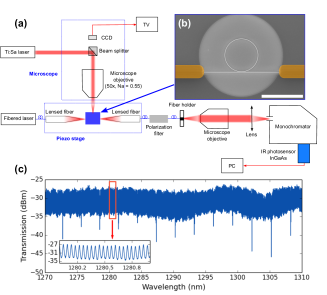
Photonic structures are made from SOI substrates, with a 220 nm silicon layer and a 2 m thick buried silicon oxyde. Waveguides and photonic cavities are defined by electron beam lithography followed by dry etching using an inductively coupled plasma. The typical width of microring resonators is 340 nm. An additional lithography step was performed to form a local cladding (height ) for waveguides, using Hydrogen SilsesQuioxane (HSQ). After patterning, HSQ was processed into a silica-like layer, in order to achieve mode symmetrisation and waveguides isolation from carbon nanotubes outside well-defined interaction regions. A typical SEM picture of a microring resonator (prior to nanotube deposition) coupled to an access bus waveguide is displayed in figure 1(b).
2.2 SWNT extraction and deposition
Single-wall carbon nanotube are synthesized using the HiPCO process and obtained from a commercial source (Unydim). Semiconducting SWNT were extracted using a polyfluorene (PFO) based process[24, 25, 26], known to yield to high-purity material, with no visible trace of metallic nanotubes and a handful of remaining semiconductor SWNT chiralities[26, 27]. Among them are the (8,7) and (9,7) SWNT species, with PL emission located within the telecom O Band, respectively centered at 1280 nm and 1350 nm. Therefore, this material is perfectly suitable for integration in an optical interconnect scheme based on silicon, at telecommunication wavelengths. The extracted material was then spin-casted on top of the sample at 1000 RPM during 60 s. This procedure was repeated three times to ensure the deposition of a thin and flat layer. To further increase the quantity of carbon nanotubes on the sample and in order to achieve better symmetrization of the optical mode in the exposed interaction region, a drop-casting was carried out. Finally, a thermal annealing at 180 oC during 15 min was used to cure remaining inhomogeneities in the deposited layer.
2.3 Integrated PL setup
The characterization setup is represented in figure 1(a) and is composed of a tunable fiber laser source used for inputing light into the waveguides, and a Ti:Sapphire external laser source used to pump the SWNT on their second excitonic transition S22, focused on the sample by a microscope objective (50x, NA = 0.55). The collection system is made using a polarization maintaining fiber, a polarization filter and a spectrometer composed of a 950 lines/mm grating coupled to a nitrogen-cooled InGaAs photodetector array. Depending on the experiment, the optical pump could be either the fiber laser or the Ti:Sapphire source.
3 Results and Discussion
3.1 Transmission measurements
The ring resonator transmission without carbon nanotubes on the surface was recorded. To ensure that the symmetrization of the optical mode is similar with or without presence of nanotubes, we used a liquid with a well-known refractive index (), close to the expected index for the PFO-embedded carbon nanotubes material ([28]). The experimental aparatus is similar to the one depicted schematically in figure 1(a). The set-up to measure transmission consists of a tunable fiber laser source, with a polarization control system and a lensed fiber for injection of the light into the chip. The output light is collected by a microscope objective, filtered in polarization and monitored by a photodetector.
An exemple of transmission spectrum is displayed in figure 1(c). Injection power was 1 mW for TE polarization. The studied structure was a microring resonator with a 20 m radius. The input light from the access waveguide evanescently couples to the microring resonator and, depending of the wavelength, is able to excite a resonance mode of the ring, leading to this periodically spaced transmission dips. Microring resonators are caracterized by the interval between two adjacent dips, namely the Free Spectral Range (FSR), which is given by :
where are the center wavelength of the two adjacent dips considered, the group index of the mode ( at 1300 nm for TE polarization) and the cavity length is , with the ring radius. On Fig 1c, the FSR was estimated to nm around 1.3 m for a microring of 20 m radius, which is consistent with the expected group index of . Note that the FSR error bar given represents the fit error. The oscillations observed between the cavity modes were Fabry-Pérot fringes, as visible in the inset in figure 1(c). They originate in the reflection at the sample facets and are not noise in nature.
3.2 Externally pumped PL
By using a Ti:Sapphire external laser source, SWNT could be resonantly excited on their excitonic transition. The setup is represented in figure 1(a), where the Ti:Sapphire laser source is focused on the sample using a 50x microscope objective. Light emitted by carbon nanotubes (over their excitonic transition) excites a resonance mode of the microring and evanescently couples to the access waveguide. Light was then collected at the waveguide output by a lensed optical fiber. Additionnaly, a polarizer enables to discriminate either TE or TM polarizations at the output.
The figure 2 displays the three possible collected PL spectra : (a) without polarization filter, (b) TE-filtered and (c) TM-filtered.
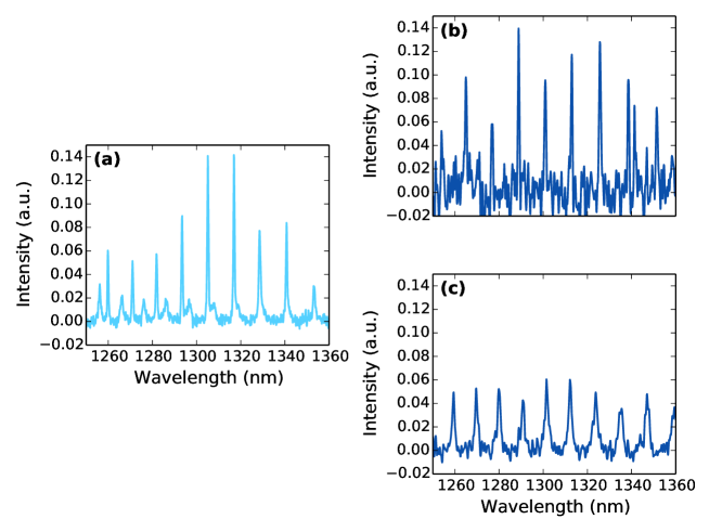
On each spectrum, evenly spaced narrow peaks are visible, corresponding to ring resonance modes excited by nanotube photoluminescence. Interestingly, the SWNT broadband PL background[22] is not observed in this configuration, which we attribute to the intensity ratio of microring resonant mode. Indeed, on the transmission spectra displayed in figure 1(b), the extinction ratio is as high as 13 dB. Thus, this configuration allows to efficiently reject the uncoupled SWNT PL background, keeping only resonant photons with high spectral purity.
| FWHM (nm) | FSR (nm) | |
|---|---|---|
| Unpolarized output (set 1) | 0.67 0.09 | 11.56 0.48 |
| Unpolarized output (set 2) | 1.26 0.31 | 10.54 0.70 |
| TE polarized output | 0.71 0.14 | 12.08 0.62 |
| TM polarized output | 1.41 0.22 | 10.83 0.56 |
Unpolarized spectrum (figure 2(a)) clearly shows two peak sets that are not observed on both polarized spectra (figures 2(b) and (c)). Unpolarized and polarized spectra were deconvoluted with a Lorentzian fit to extract the Full-Width Half-Maximum (FWHM) of the peaks and the FSR. Corresponding data are summarized in table 1.
The extracted FWHM on the polarized output is 0.710.14 nm for the TE polarization and 1.410.22 nm for TM polarization. On the other hand, the unpolarized PL spectrum clearly shows that the two peak sets have differents FWHM. The deconvoluted narrow set had a FWHM of 0.670.09 nm and was attributed to the TE polarization modes, while the broader set had a FWHM of 1.260.31 nm and was attributed to the TM polarization. Thus, we conclude that the two peak sets observed in the unpolarized spectrum arise from both fundamental polarizations, TE and TM, propagating in the microring resonator, as previously suggested[22].
We also notice that both TE and TM peak sets have a slightly different FSR. Estimated FSR range from 10.5 to 12 nm, with a FSR slightly larger for TE polarization, and are consistent between unpolarized and polarized output. The observed correspondance between FSR in each type of polarization experiment supports our attribution of the TE and TM modes in the unpolarized PL spectrum.
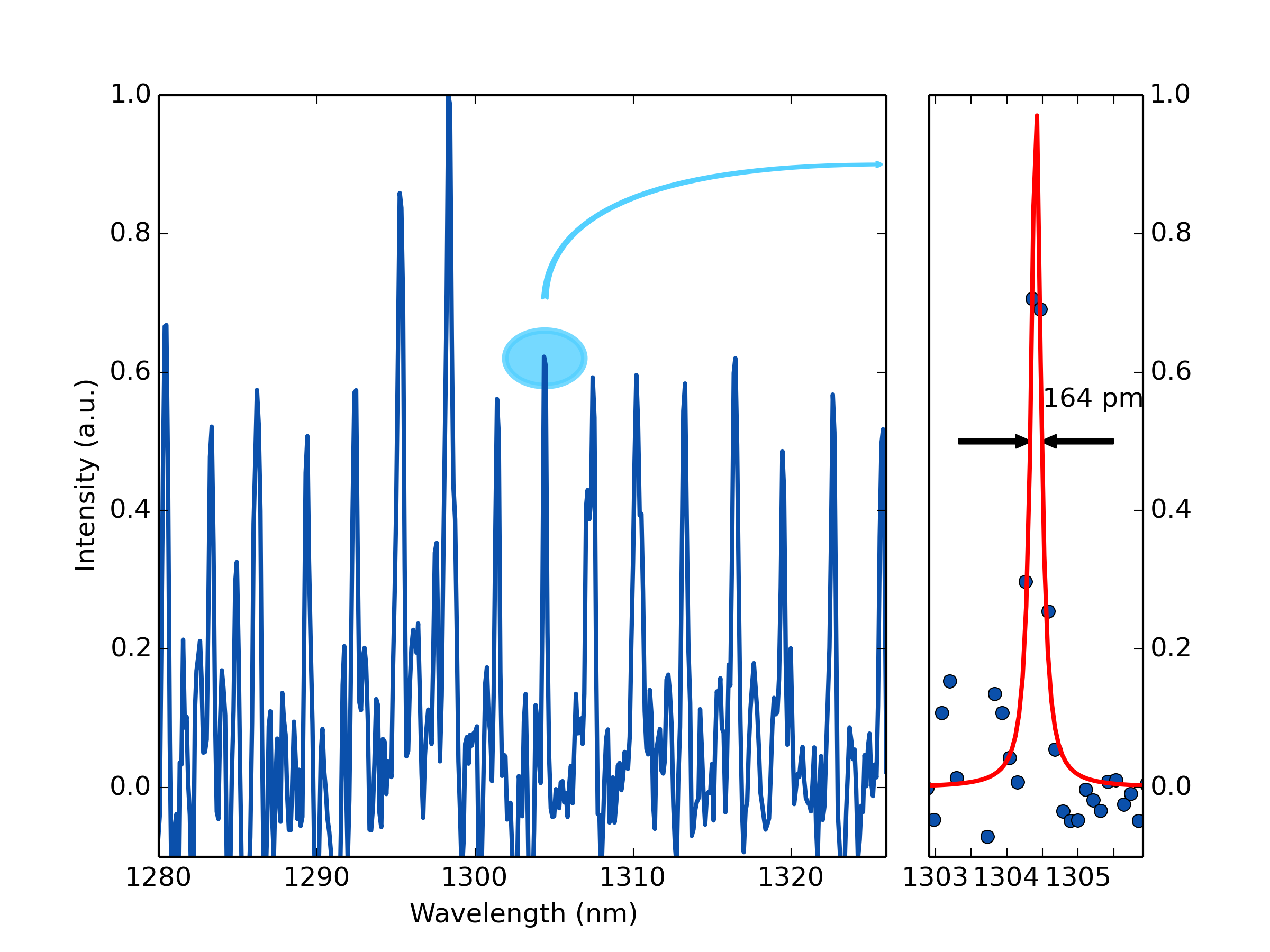
An interesting feature of ring resonators is that their quality factor scales with the radius[29], due to the reduction of the bending loss with higher ring radius. PL spectra were recorded from nanotubes coupled into microring resonators with radius up to 20 m. The figure 3 shows an exemple of PL spectra for a ring resonator with a radius of 20 m. Very sharp peaks are observed in this structure. In this case, the measured FWHM was 164 pm, corresponding to a quality factor of approximately 8000. This value is the highest reported up to date, doubling the reported quality factor[20, 22, 21] so far. Moreover, the measured quality factor is suspected to be limited by the resolution of our acquisition setup, and could probably be even higher.
3.3 Spatial cartography of excitation
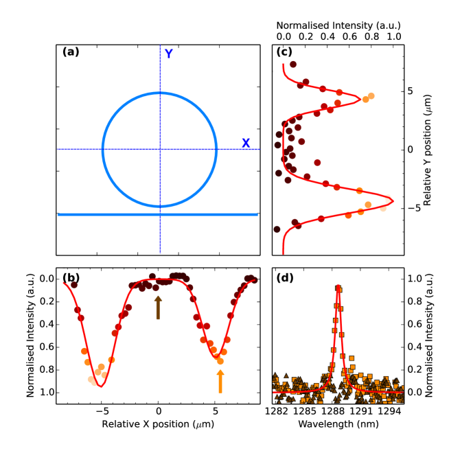
The integrated measurement set-up (sample and fibers) was assembled on a piezo stage controller in order to record a spatial cartography of the photoluminescence. Such an experiment was performed by moving the excitation beam over the ring resonator while recording a photoluminescence spectra in a narrow window, in order to minimize the drift in the collection fiber position. Two PL spectra, corresponding to a beam located on the right side of the ring (square, orange) and 5 m away from the ring (triangle, brown), are displayed in figure 4(d). A 1 nm wide spectral window was integrated over the displayed peak. The results, as a function of spatial coordinates, are reported on both axes in figures 4(b) and (c).
Two maxima are observed on each plot and are attributed to the overlap between the gaussian profile of the excitation laser and the gaussian profile of the studied resonance mode of the microring resonator. It is reasonable to consider that the 340 nm wide waveguide has a negligible size compared to the pump laser beam waist, i.e. that the mode extension[6] of the microring is much smaller than the laser beam extension, . Therefore, it is possible to recover the beam profile by directly fitting the two observed peaks. The beam profile was determined to be =m. The spacing between these two peaks fits with the microring diameter, =m, emphasizing the fact that the observed sharp peaks on the PL spectra originate from the microring cavity modes. Moreover, this spatial cartography indicates that SWNT excitation is homogeneous on different quadrants. This means that the microring mode excitation did not rely on some hot-spot, but rather that the excitation is delocalized on the whole microring length.
Interestingly, the spectra for a pump beam several microns away from the ring, displayed in figure 4(d), shows no trace of the SWNT PL. Nevertheless, it is reasonable to consider that the spot is located on some carbon nanotubes, since our deposition method does not localize nanotubes only on the ring walls. We can then conclued that the nanotubes excited here do not couple to the ring resonator. Therefore, this observation reveals that when such coupling occurs, it is only mediated by near-field interaction between SWNT - acting as a light emitting dipole - and the optical modes of the ring resonator.
3.4 Degenerated PL via collinear excitation
To demonstrate the full potential of SWNT in an integrated configuration, we took advantage of the microring configuration to pump SWNT through the access waveguide. The Ti:Sapphire laser source was replaced by a fibre laser source. In this configuration, the optical pumping was achieved above the first SWNT excitonic transition S11, since the silicon access waveguide and microring could only transmit near-IR light.
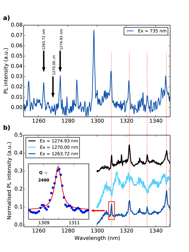
First, the pumping wavelength was selected by looking at a Ti:Sapphire excited PL spectrum, displayed in figure 5(a), recorded in the same conditions as previously shown (TE-polarized output). Wavelengths of interest for integrated pumping (TE polarized pump laser) were identified: two of them were chosen in resonance with the microring mode, respectively at 1263.72 nm and 1274.93 nm, while one was chosen out of resonance at 1270.00 nm. When setting such wavelengths with the pump fibre laser, close to the acquisition window, it is necessary to reject the transmitted pump residual. This is achieved by placing a free-space low-pass filter with a cut-off wavelength of 1300 nm in front of the entrance of the spectrometer.
PL spectra recorded at the waveguide output using these three different excitation wavelengths are displayed in figure 5(b), for TE polarization.
When the pumping wavelength was matching a resonance of the microring, either at 1263.72 nm or 1274.93 nm (dark blue and black plots in figure 5(b)), the PL spectra displayed evenly spaced peaks. The locations of these photoluminescence peaks are in agreement with the reference spectra, as highligted by the dotted lines. We then conclude that these peaks originate from the ring resonance modes excited by the nanotubes.
The fact that these peaks were absent in the case of the non-resonant pump (light blue in figure 5(b)) allows to understand precisely the mecanism involved here: light inputed through the waveguide evanescently couples in the latter. This coupled light excited nanotubes just above their first excitonic transition. If the pump wavelength matches a resonance of the ring resonator, the excitation is much more efficient due to the long photon lifetime time in the resonator. After relaxing to the first excitonic state, part of the energy was emitted back by the nanotube through photons, the number of emitted photons being controlled by the nanotubes internal quantum yield. The emitted photons coupled to lower energy resonance modes of the microring (i.e., higher wavelength). These excited resonance peaks of the ring then evanescently coupled to the bus waveguide and were collected at the sample output.
Noticeably, some dips are also observed in figure 5(b) in the case of non-resonant pump, matching the resonance peaks highlighted by the dotted lines. This is attributed to the remnant of the pump laser, not completely extinguished by the low-pass filter and responsible for the broad background observed, which is filtered by the microring cavity mode.
We finally note that, in this configuration, the output light intensity was higher compared to the situation where the PL spectra are excited by the Ti:Sapphire. Indeed, if we compare the emission area of the peak centered at 1347 nm and normalize it by the respective excitation pump power, we find an area of 529.3 photons/W and 20.1 photons/W for collinear pumping () and for Ti:Sa pumping () respectively. This leads to an increase of the emission by a factor higher than 26, which is attributed to the more efficient excitation scheme involved when pumping nanotubes by the resonance mode of the ring, rather than exciting them by an external pump. Again, this shows the strength of such a fully-integrated approach to excite SWNT PL.
4 Conclusion
In conclusion, we have demonstrated the coupling of carbon nanotubes photoluminescence with silicon microring resonators in a fully integrated configuration. This powerful approach make possible the collection of SWNT PL at a long distance after the microring resonator, enabling information transmission within an integrated optical link. Plus, the integrated approach reported here led to the elucidation of the polarization effect occuring in microring resonators that were previously suspected[22]. It was demonstrated that the fundamental polarizations TE and TM could propagate in the microring resonator, with a slightly different FSR.
A spatial cartography of the photoluminescence was also performed, demonstrating that SWNT excitation is delocalised on the whole microring length and did not originate from an hot-spot, but was based on near-field coupling between SWNT and the optical modes of the microring.
The quality factor of the emission peaks achieved here reached up to 8000 for 20 m radius microring, doubling the previously reported values. Finally, we demonstrated the successful pumping of SWNT through the access waveguide, displaying a higher overall emission, compared to the externally pumped configuration, with an increase of emission by a factor more than 26.
Pumping on the first excitonic transition of SWNT is easier to implement because it lifts the requirement of an external source and takes advantage of the silicon transparency to propagate the excitation wave. We demonstrated that such an excitation path is highly efficient in microring resonators if realized on a higher energy resonance of the ring, as reported in other types of cavities[20, 30].
As quality factor of ring resonator scales with the ring radius, it is expected that the measured quality factor can be greatly improved by increasing the ring dimensions. Combining high-Q cavity with simple design, an efficient excitation scheme, and a material displaying optical gain[4] is expected to lead to the demonstration of SWNT based laser.
The analysis of the different pumping schemes, on/off resonance, allowed us to understand the mechanisms of the interaction between the optical mode of the resonator and SWNT deposited on the microring. Such a precise understanding is valuable for the design of more efficient interaction schemes for SWNT or any material in photonic cavity.
Acknowledgments
A. Noury acknowledges the Ministry of Higher Education and Research (France) for scholarship. The authors acknowledge A. Degiron for assistance and fruitful discussions. This work has been supported by ANR JCJC project ”Ça (Re-) Lase !”, by the Region Ile-de-France in the framework of DIM Nano-K (project CANOA) and by the FET project ”Cartoon”. Fabrication was performed in the IEF clean room facilities (CTU/MINERVE), part of the RENATECH network.
References
References
- [1] M. Freitag, M. Steiner, A. Naumov, J.P. Small, A.A. Bol, V. Perebeinos, and P. Avouris. Carbon nanotube photo- and electroluminescence in longitudinal electric fields. ACS Nano, 3:3744, 2009.
- [2] Y. Miyauchi, H. Hirori, K. Matsuda, and Y. Kanemitsu. Radiative lifetimes and coherence lengths of one-dimensional excitons in single-walled carbon nanotubes. Phys. Rev. B, 80:081410(R), 2009.
- [3] T. Hertel, S. Himmelein, T. Ackermann, D. Stich, and J. Crochet. Diffusion limited photoluminescence quantum yields in 1-d semiconductors: Single-wall carbon nanotubes. ACS Nano, 4:7161, 2010.
- [4] E. Gaufrès, N. Izard, X. Le Roux, D. Marris-Morini, S. Kazaoui, E. Cassan, and L. Vivien. Optical gain in carbon nanotubes. Appl. Phys. Lett., 96:231105, 2010.
- [5] M. Yoshida, Y. Kumamoto, A. Ishii, A. Yokoyama, and Y.K. Kato. Stark effect of excitons in individual air-suspended carbon nanotubes. Appl. Phys. Lett., 105:161104, 2014.
- [6] E. Gaufrès, N. Izard, A. Noury, X. Le Roux, G. Rasigade, A. Beck, and L. Vivien. Light emission in silicon from carbon nanotubes. ACS Nano, 6:3813, 2012.
- [7] S. Khasminskaya, F. Pyatkov, B.S. Flavel, W.H. Pernice, and R. Krupke. Waveguide-integrated light-emitting carbon nanotubes. Adv. Mater., 26:3465, 2014.
- [8] K. J. Vahala. Optical microcavities. Nature, 424:839, 2003.
- [9] F. Xia, M. Steiner, Y.-M. Lin, and P. Avouris. A microcavity-controlled, current-driven, on-chip nanotube emitter at infrared wavelengths. Nature Nanotech., 3:609, 2008.
- [10] D. Legrand, C. Roquelet, G. Lanty, P. Roussignol, X. Lafosse, S. Bouchoule, E. Deleporte, C. Voisin, and J.S. Lauret. Monolithic microcavity with carbon nanotubes as active material. Appl. Phys. Lett., 102:153102, 2013.
- [11] M. Fujiwara, D. Tsuya, and H. Maki. Electrically driven, narrow-linewidth blackbody emission from carbon nanotube microcavity devices. Appl. Phys. Lett., 103:143122, 2013.
- [12] E. Gaufrès, N. Izard, X. Le Roux, S. Kazaoui, D. Marris-Morini, E. Cassan, and L. Vivien. Optical microcavity with semiconducting single-wall carbon nanotubes. Opt. Express, 18:5740, 2010.
- [13] E.M. Purcell. Spontaneous emission probabilities at radio frequencies. Phys. Rev., 69:674, 1946.
- [14] J. P. Reithmaier, G. Sek, A. Loffler, C. Hofmann, S. Kuhn, S. Reitzenstein, L. V. Keldysh, V. D. Kulakovskii, T. L. Reinecke, and A. Forchel. Strong coupling in a single quantum dot-semiconductor microcavity system. Nature, 432:197, 2004.
- [15] Luca Sapienza, Henri Thyrrestrup, Søren Stobbe, Pedro David Garcia, Stephan Smolka, and Peter Lodahl. Cavity quantum electrodynamics with anderson-localized modes. Science, 327:1352, 2010.
- [16] E. Peter, P. Senellart, D. Martrou, A. Lemaitre, J. Hours, J. Gerard, and J. Bloch. Exciton-photon strong-coupling regime for a single quantum dot embedded in a microcavity. Phys. Rev. Lett., 95:067401, 2005.
- [17] Martin T. Hill, Harmen J. S. Dorren, Tjibbe de Vries, Xaveer J. M. Leijtens, Jan Hendrik den Besten, Barry Smalbrugge, Yok-Siang Oei, Hans Binsma, Giok-Djan Khoe, and Meint K. Smit. A fast low-power optical memory based on coupled micro-ring lasers. Nature, 432:206, 2004.
- [18] R. Watahiki, T. Shimada, P. Zhao, S. Chiashi, S. Iwamoto, Y. Arakawa, S. Maruyama, and Y. K. Kato. Enhancement of carbon nanotube photoluminescence by photonic crystal nanocavities. Appl. Phys. Lett., 101:141124, 2012.
- [19] H. Sumikura, E. Kuramochi, H. Taniyama, and M. Notomi. Cavity-enhanced raman scattering of single-walled carbon nanotubes. Appl. Phys. Lett., 102:231110, 2013.
- [20] S. Imamura, R. Watahiki, R. Miura, T. Shimada, and Y. K. Kato. Optical control of individual carbon nanotube light emitters by spectral double resonance in silicon microdisk resonators. Appl. Phys. Lett., 102:161102, 2013.
- [21] R. Miura, S. Imamura, R. Ohta, A. Ishii, X. Liu, T. Shimada, S. Iwamoto, Y. Arakawa, and Y.K. Kato. Ultralow mode-volume photonic crystal nanobeam cavities for high-efficiency coupling to individual carbon nanotube emitters. Nat. Commun., 5:5580, 2014.
- [22] A. Noury, X. Le Roux, L. Vivien, and N. Izard. Controlling carbon nanotube photoluminescence using silicon microring resonators. Nanotechnology, 5:215201, 2014.
- [23] Y.K. Kato. Illuminating the future of silicon photonics: optical coupling of carbon nanotubes to microrings. Nanotechnology, 26:070501, 2015.
- [24] Adrian Nish, Jeong-Yuan Hwang, James Doig, and Robin J. Nicholas. Highly selective dispersion of single-walled carbon nanotubes using aromatic polymers. Nat. Nano, 2:640, 2007.
- [25] Fuming Chen, Bo Wang, Yuan Chen, and Lain-Jong Li. Toward the extraction of single species of single-walled carbon nanotubes using fluorene-based polymers. Nano Lett., 7:3013, 2007.
- [26] N. Izard, S. Kazaoui, K. Hata, T. Okazaki, T. Saito, S. Iijima, and N. Minami. Semiconductor-enriched single wall carbon nanotube networks applied to field effect transistors. Appl. Phys. Lett., 92:243112, 2008.
- [27] E. Gaufrès, N. Izard, L. Vivien, S. Kazaoui, D. Marris-Morini, and E. Cassan. Enhancement of semiconducting single-wall carbon-nanotube photoluminescence. Opt. Lett., 34:3845, 2009.
- [28] M. Campoy-Quiles, P.G. Etchegoin, and D.D.C. Bradley. Exploring the potential of ellipsometry for the characterisation of electronic, optical, morphologic and thermodynamic properties of polyfluorene thin films. Synthetic Metals, 155:279, 2005.
- [29] M. Peccianti, A. Pasquazi, Y. Park, B.E. Little, S.T. Chu, D.J. Moss, and R. Morandotti. Demonstration of a stable ultrafast laser based on a nonlinear microcavity. Nat. Commun., 3:765, 2012.
- [30] X. Liu, T. Shimada, R. Miura, S. Iwamoto, Y. Arakawa, and K. Kato, Y. Localized guided-mode and cavity-mode double resonance in photonic crystal nanocavities. Phys. Rev. Applied, 3:014006, 2015.