eurm10 \checkfontmsam10 \pagerange119–126
Imposed magnetic field and hot electron propagation in inertial fusion hohlraums
Abstract
The effects of an imposed, axial magnetic field on hydrodynamics and energetic electrons in inertial confinement fusion (ICF) indirect-drive hohlraums are studied. We present simulations from the radiation-hydrodynamics code HYDRA of a low-adiabat ignition design for the National Ignition Facility (NIF), with and without Tesla. The field’s main hydrodynamic effect is to significantly reduce electron thermal conduction perpendicular to the field. This results in hotter and less dense plasma on the equator between the capsule and hohlraum wall. The inner laser beams experience less inverse bremsstrahlung absorption before reaching the wall. The x-ray drive is thus stronger from the equator with the imposed field. We study superthermal, or “hot,” electron dynamics with the particle-in-cell code ZUMA, using plasma conditions from HYDRA. During the early-time laser picket, hot electrons based on two-plasmon decay in the laser entrance hole (Regan et al., 2010) are guided to the capsule by a 70 T field. 12x more energy deposits in the deuterium-tritium (DT) fuel. For plasma conditions early in peak laser power, we present mono-energetic test-case studies with ZUMA as well as sources based on inner-beam stimulated Raman scattering. The effect of the field on DT deposition depends strongly on the source location, namely whether hot electrons are generated on field lines that connect to the capsule.
1 Introduction
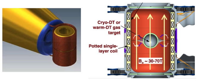
Using a magnetic field to enhance inertial fusion is an old idea (Jones & Mead, 1986) receiving renewed interest (Slutz & Vesey, 2012). An imposed field is being investigated at LLNL as a way to improve capsule performance and achieve ignition on NIF (Perkins et al., 2013, 2014; Ho, 2015). These simulation studies show an initial field of 40-70 T increases both the likelihood of ignition and the fusion yield by reducing electron-heat and alpha-particle loss from the hot spot. Earlier experiments at the Omega laser facility with an imposed 8 T axial field show increased fusion yield and ion temperature in spherical implosions (Chang et al., 2011; Hohenberger et al., 2012). The field may also limit hydrodynamic (e.g. Rayleigh-Taylor) instability growth, and reduce the negative effects of the growth that does occur. The field also increases the plasma temperature in the underdense hohlraum fill, which could reduce SRS and improve laser propagation to the wall (Montgomery et al., 2015). A pulsed-power approach is being developed to impose T on a NIF hohlraum (Rhodes et al., 2015), and is sketched in Fig. 1. Laser-driven capacitor-coil systems are a possible way to impose 100-1000 T fields (Fujioka et al., 2013; Pollock et al., 2014).
This paper presents simulation studies of how an imposed field affects hohlraum hydrodynamics and energetic electrons. First, we report on simulations using the radiation-hydrodynamics code HYDRA (Marinak et al., 2001) with and without an imposed field of ignition experiment N120321. Then we show studies with the particle-in-cell code ZUMA (Larson et al., 2010; Strozzi et al., 2012) of the field’s effect on energetic or “hot” electrons.
We study NIF shot N120321, which used a 4-shock, low-adiabat or “low-foot” laser pulse, a plastic ablator, and a cryogenic DT ice layer. It achieved the highest fuel areal density to date on NIF, and has been extensively modeled to understand its low neutron yield (Clark et al., 2015). Here, we use HYDRA’s magnetohydrodynamics (MHD) package (Koning et al., 2006) with T, which was not present in the actual experiment. We include the magnetic pressure force, a simple Ohm’s law , Ohmic heating, and anisotropic electron thermal conductivities parallel and perpendicular to (but not the Righi-Leduc heat flow along ). This neglects several effects which could be important, and will be studied in future work, namely the self-generated or “Biermann battery” field and the Nernst effect (). In our runs, the field roughly follows the MHD “frozen-in law” for the highly-conducting plasma flow. The primary effect of the field is to reduce electron heat conduction perpendicular to . This leads to a hotter hohlraum fill, and a wider channel between the capsule and hohlraum equator. The inner cone of beams (pointed toward the equator) better propagate to the wall, which gives more equatorial x-ray drive and a less oblate imploded capsule. This would reduce the need for energy transfer to the inners, and probably reduce their backscatter - both due to the lower power and higher temperature.
Besides hydrodynamics, we also study hot electron dynamics. Hot electrons are a generic aspect of intense laser-plasma interactions (LPI). They are produced in any parametric process that drives a Langmuir wave. Of particular interest in ICF are stimulated Raman scattering (SRS) and two-plasmon decay (TPD). These are the decay of a light wave to a Langmuir wave and, respectively, a scattered light wave (SRS) or another Langmuir wave (TPD). In many laser-produced plasmas, the daughter Langmuir waves are damped primarily by collisionless Landau damping, which entails the resonant interaction of the wave with electrons at its phase velocity. This is typically greater than the electron thermal speed, and therefore produces a population of superthermal or “hot” electrons. Experiments show the resulting hot-electron spectrum from a single parametric process is roughly exponential with “temperature” , ( is the hot electron kinetic energy), with for a non-relativistic Maxwellian. NIF experiments with gas-filled hohlraums have shown hard x-ray output consistent with a two-temperature hot-electron population, attributed to Raman backscatter, and TPD or SRS at quarter-critical density (Döppner et al., 2012). Relativistic processes that produce MeV electrons at intensities W cm-2 m2 are of great interest in the short-pulse and fast-ignition fields, but are not discussed here.
This paper focuses on hot electrons in ignition hohlraums, though similar considerations apply to directly-driven targets. Hot electrons impede ICF in several ways, namely implosion asymmetry and fuel preheat. The laser power transferred to hot electrons generally stays in the target, so is not a power loss like backscattered light. But, the deposition in space and time differs from the intended inverse-bremsstrahlung absorption of the incident laser. NIF hohlraums with high hohlraum gas fill density ( mg cm-3 He) have generally shown large SRS from the inner beams. This reduces the inner-beam power reaching the wall – both by scattered light and Langmuir waves – which makes the implosion more oblate (or “pancaked”). The Langmuir wave energy remains in the target, but heats the hohlraum wall by conduction in a much larger area than the inner-beam spots. To control symmetry, cross-beam energy transfer has been used to move power from the outer to inner beams, inside the target (Michel et al., 2009). Hot electrons with energy keV can also preheat the fusion fuel (e.g., cryogenic DT ice layer) by depositing energy separate from the intended shock sequence and capsule compression (Salmonson et al., 2010; Haan et al., 2011). This results in a higher fuel adiabat, which significantly reduces the achievable compression.
We propagate hot electrons with the hybrid-PIC code ZUMA through plasma conditions from HYDRA. We run ZUMA in a “Monte-Carlo mode” with no or fields, except sometimes a static . Hot electrons undergo energy loss and angular scattering as they propagate, and the energy deposition profile is found with and without an initial . We first present an unphysical test-case study of mono-energetic hot electrons directly incident on the capsule (unrealistic for LPI-produced hot electrons) early in peak laser power (time 18 ns). A minimum initial energy 125 keV is needed to penetrate the ablator and reach the DT layer. The maximum energy deposited in the DT layer, , occurs for 185 keV and is . Higher energy electrons do not fully stop in DT.
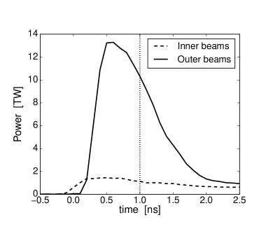
We then examine a realistic hot-electron source, consistent with two-plasmon decay during the early-time “picket” or initial part of the laser pulse (time 1 ns). The deposition is mostly in the high- wall, as expected from solid-angle arguments, and with the total injected hot electron energy. Adding a uniform 70 T axial field strongly magnetizes the hot electrons in the hohlraum fill, guides them to the capsule, and increases by 12x to 0.026. This may not degrade fusion performance, since NIF experiments have shown greatly reduced picket hot electrons with pulse shaping, e.g. a low-power “toe” to burn down the window (Dewald et al., 2015; Moody et al., 2014).
Finally, we consider a hot-electron source consistent with SRS of the inner laser beams, early in peak laser power (18 ns). With no , the hot electrons deposit throughout the target, with a very small . With T, the field strongly magnetizes the hot electrons in the hohlraum fill gas. The deposition in DT is greatly increased (decreased) for hot electrons originating on field lines that do (do not) connect to the capsule at this time.
This paper is organized as follows. We describe our MHD simulation methodology in section 2 and our MHD results in section 3. The ZUMA simulation method is detailed in section 4. Section 5 discusses test cases of mono-energetic electron propagation through the capsule. Section 6 presents ZUMA results for a TPD-relevant source during the picket, and shows a 12x increase in with a 70 T axial field. In section 7 we present ZUMA results early in peak laser power with an SRS-relevant hot electron source, using plasma conditions and the field from our HYDRA simulations, and find a strong dependence in on source location. We conclude in section 8.
2 HYDRA MHD simulation method
We use the radiation-hydrodynamics code HYDRA to simulate the NIF hohlraum experiment N120321. This shot used a 4-shock, “low-foot” laser pulse (shown in Fig. 2), a plastic ablator (C0.42H0.57 plus small amounts of O impurity, and Si dopant to control x-ray preheat) with a DT ice layer, and a depleted uranium (DU) hohlraum with a thin 0.7 m inner gold coating. The hohlraum fill gas was 0.96 mg cm-3of He. The methodology is the standard one in use for hohlraum simulations at LLNL (Jones et al., 2012), entailing the “high-flux model” with detailed configuration accounting (DCA) for non-LTE material properties, and an electron thermal flux limit of 0.15 the free-streaming value (Rosen et al., 2011). The runs use a 3D mesh with one zone and periodic boundary conditions in azimuth, and are effectively cylindrical 2D (r-z). The mesh is managed with an arbitrary Lagrangian-Eulerian (ALE) approach, designed to keep the mesh as Lagrangian as possible. We use the full, incident laser energy of 1.52 MJ, and neither remove measured backscatter nor degrade the laser power as is needed to match x-ray drive data in high gas fill targets (Jones et al., 2012). Our HYDRA simulations are therefore not proper post-shots, but address the role of an imposed field in ignition-scale designs, and provide relevant plasma conditions for hot electron studies.
A distinct aspect of the present work is the inclusion of an initial axial magnetic field . HYDRA’s magnetohydrodynamics (MHD) package (Koning et al., 2006) was used to model and the resulting required by . No azimuthal field is produced for our axisymmetric geometry and simple Ohm’s law. The MHD package uses a 3D finite element method, with appropriate boundary conditions to be effectively axisymmetric. We used the Ohm’s law
| (1) |
where , , and are scalar resistivity, net current, and center-of-mass velocity, respectively. The field is evolved via . The MHD package as used here affects the matter in three ways: a) the force, b) (Ohmic) and other heating terms, and c) a tensor electron thermal conductivity:
| (2) |
The Righi-Leduc effect, with a separate conductivity along , is currently neglected( is electron temperature). An artificial flux limit is imposed, as is typical in hohlraum simulations. Specifically, the component of the heat flux along each logical index (not physical) coordinate is limited: where is the free-streaming heat flux.
The anisotropic heat conduction has the largest effect in our simulations. We expect T to significantly reduce below its unmagnetized value . The Hall parameter for thermal electrons is
{subeqnarray}
H &≡ ω_ceτ_ei = B B0,
B_0 ≡ (32π)^1/2 3m_e^1/2e^3 (4πϵ0)2 n_e Te3/2 ,
≡ ∑_if_iZ_i^2lnΛ_ei ∑ifiZi.
For each ion species is the ionic (not nuclear) charge, ,
and is the total ion number density. In practical units, with cm-3 the critical density for light of wavelength 351 nm. For He at and keV, typical of the underdense hohlraum fill, we find and T. Given T, most of the underdense plasma fill should be strongly magnetized. decreases with according to
| (3) |
with the -dependent fitting coefficients given in Epperlein & Haines (1986). For He, for . is found either from the Lee & More (1984) formulation to include dense-plasma effects, or interpolation from an advanced table. The Epperlein and Haines results are used to include electron self-collisions () and dependence on .
3 MHD simulation results
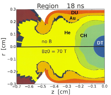
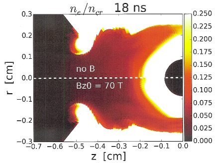
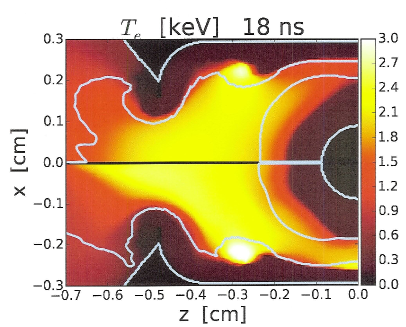
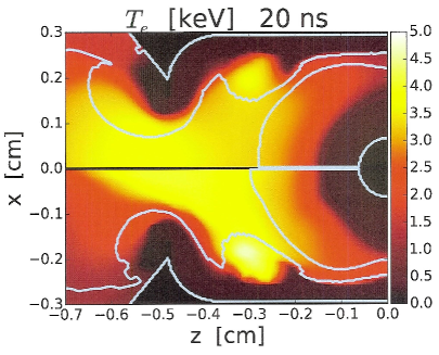
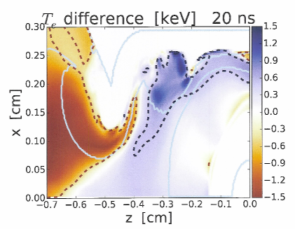
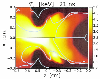
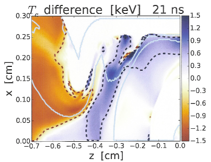
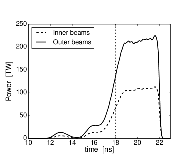
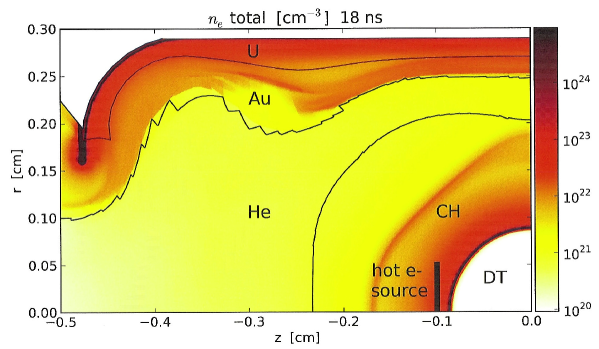
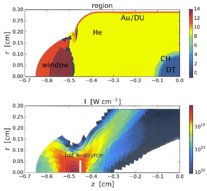
The HYDRA runs of NIF shot N120321 with and without MHD are qualitatively similar. The principal difference is the MHD run has higher electron temperature in some regions and a wider channel of He fill gas at the equator. This leads to better inner beam propagation to the wall (less inverse-bremsstrahlung absorption in the low- fill), and results in a less oblate capsule. Figure 3 shows the material regions and electron density for the two runs at 18 ns, during the rise to peak power. We use this time for ZUMA simulations of SRS hot electrons. A more detailed density plot is in Fig. 7. Electron temperature with and without MHD at several times during peak power is displayed in Fig. 4. The field increases mainly in the laser-heated gold, such as the outer-beam “bubble” cm. The He gas fill is also hotter with the field, but less so than the gold. The low density plasma outside the laser entrance hole (LEH) is cooler with the field, though the total energy in this region is small.
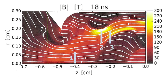
The field for the MHD run is plotted in Fig. 5. It roughly follows the MHD frozen-in law, and advects with the radial motion of the ablator and high- wall. The compressed field approaches 300 T and continues to grow with time. The white stream line that just touches the capsule outer radius at roughly separates field lines that are still connected to the capsule ( cm at ), from those that have advected with the ablated blowoff and no longer connect to the capsule.
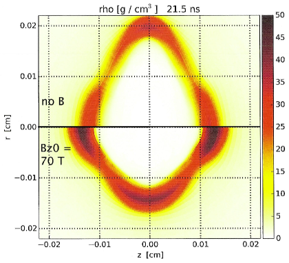
The capsule density at the end of peak power is plotted in Fig. 6. The dense fuel is oblate without the field, but becomes close to round with it.
4 ZUMA Hot electron simulation method
We propagate hot electrons through fixed plasma conditions from
HYDRA using the hybrid-PIC code ZUMA in a “Monte-Carlo” mode.
We do not include forces from and fields, except when we
include a specified (static) field. The background plasma
properties are not updated. In other work, HYDRA and ZUMA have
been coupled to run in tandem, and applied to fast ignition designs
(Strozzi et al., 2012). The hot electrons undergo collisional
energy loss off background electrons, and angular scattering off
background electrons and ions. We neglect collisions among hot
electrons, since their density is much less than the background
species. We use the formulas in Robinson et al. (2014) for a
fast electron with . The energy loss rate (stopping
power) is given by
{subeqnarray}
dEdt &= C_e n_e mevL_d
≈ C_e n_e 2meE lnEℏωp, ℏω_p ≪E ≪m_ec^2,
L_d = lnpv ℏωpγ+1 - ln22 + 916 +
ln2+1/8γ(12γ-1).
, the fast electron kinetic energy , is the Lorentz factor, and . is the total (free plus bound) background electron
density. given above is valid for energy loss off free electrons, or bound electrons
for sufficiently high or (the “density effect”). This assumption may not be valid for all electrons. The angular scattering rate is
{subeqnarray}
d⟨θ^2⟩dt &= 2C_e p2v
[ n_I ⟨Z^2 ⟩L_si + n_e,fL_se ]
≈ C_e 2meE3/2 [ n_I ⟨Z^2 ⟩+ n_e,f ] ln2(2T_eE)^1/2 ℏωp, (ℏω_p)^2 Te ≪E ≪m_ec^2,
L_si = ln2l_spℏ - 0.234 - 0.659v^2/c^2,
L_se = L_si -12lnγ+32.
is the free electron density,
and we use the same ion species
notation as after Eq. 2 except is the nuclear (not ionic)
charge. is a screening length, which we take to be the free
electron Debye length. For neutral atoms, it should be replaced by the
atomic radius. In any event, we impose a minimum of 1 on ,
, and .
We run ZUMA in 2D cylindrical geometry. ZUMA currently operates with constant (but different) grid spacings and . The HYDRA plasma conditions are interpolated onto a uniform mesh with m using the OVERLINK package (Grandy, 1999). This small spacing is needed to resolve small features, such as the gold wall and DT layer. The ZUMA time step is 1 fs, which is chosen to adequately resolve the dependence of on for small and high . ZUMA stops following electrons when 5.11 keV and locally deposits their kinetic energy. In this paper, ZUMA injects hot electrons from a distribution that is a product of an energy spectrum times a polar angle spectrum . For a thermal spectrum with a “temperature” , we use a relativistic Maxwell-Jüttner distribution:
| (4) |
is a normalization constant, and the two bracketed factors are absent for a non-relativistic Maxwellian.
5 Mono-energetic electron propagation through capsule at peak power: CAPTEST series
This section considers the propagation of electrons directly incident on the capsule during peak laser power, as a function of electron energy. We call this the CAPTEST series of ZUMA runs, and stress this source is not realistic for LPI-generated hot electrons. Rather, our purpose is to understand where electrons that reach the capsule deposit their energy, and which energies pose the greatest preheat risk. We use plasma conditions from our HYDRA simulation of NIF shot N120321 with no MHD at time 18 ns. The same conditions are used in the SRS-relevant SRSPEAK series discussed below in section 7. The time 18 ns is during the rise to peak power (see Fig. 2) and has significant inner-beam SRS. An analogous time in shock-timing (“keyhole”) shots has been identified as possibly having a large hot-electron preheat effect (Robey et al., 2014).
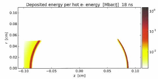
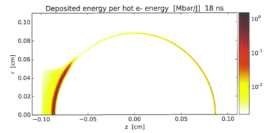
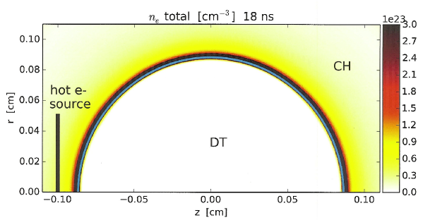
Figure 7 shows the total (free plus atomically bound) electron density in the HYDRA simulation. Mono-energetic hot electrons are injected in a cylinder of radius 500 m at cm, with an initial velocity in the direction. The hot electrons experience energy loss and (in some runs) angular scatter, but no forces from or fields. The resulting energy deposited per volume, zoomed on the capsule, is plotted in Fig. 8. The case with angular scattering shows large spreading of the hot electrons in the dense CH ablator. Since the absolute number of hot electrons introduced is arbitrary, we express the deposition as energy density per injected hot electron energy.
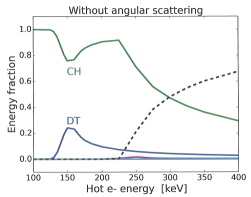
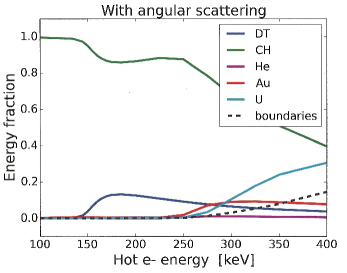
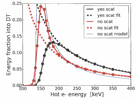
We plot the fraction of injected energy that is deposited in various regions, or escapes to the boundaries, in Fig. 9. The deposition in DT (essentially the dense fuel layer, not the less-dense proto-hotspot) is shown in Fig. 10. All electrons with keV stop in the CH ablator. This sets a minimum energy hot electrons must have when they reach the capsule (at the time 18 ns) to reach the DT layer. Above this energy, the fraction deposited in DT increases, until the hot electrons have enough energy to not stop in the DT. With no angular scatter (left panel in Fig. 9), hot electrons eventually cross the capsule, and exit the problem through the LEH. Angular scatter lowers and spreads out the peak in coupling to DT. It also causes some hot electrons to reach the Au/U hohlraum wall. In both cases, the deposition in the He hohlraum fill gas is negligible.
A simple model illustrates the basic features of Fig. 10, especially for no angular scatter. Imagine a hot electron starting at position in the CH ablator, with initial energy and . We use a 1D slab geometry with CH from to , DT from to , and CH for . We seek the fraction of initial energy deposited in DT, , where is the energy deposited in DT. The hot electron loses energy as it moves to increasing according to , where is a constant, and we include only the leading-order dependence of stopping power on energy, for . Integrating from to gives . An electron with fully stops in the CH with , one with crosses the DT, i.e. stops at , and one with stops in the DT layer, i.e. . A straightforward calculation gives
| (5) |
and . For with small, , and for , . The simple model for , with keV and keV, is plotted as the solid blue curve in Fig. 10. The model is close to the red, no-scattering result, though the capsule curvature smears the peak compared to the simple model. Figure 10 also includes least-square power-law fits to the keV results: without angular scatter, and with scatter. These are both close to the scaling of our simple model for .
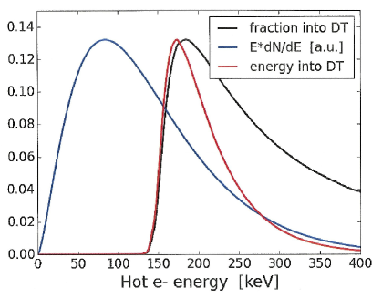
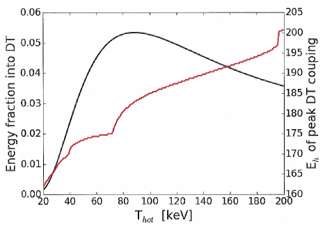
We apply our mono-energetic results to a thermal spectrum in Figs. 11 and 12, and find DT preheat comes mainly from hot electrons with energies keV, for keV. Figure 11 shows the coupling to DT of a thermal, Maxwell-Jüttner spectrum with 50 keV. The black curve is the DT coupling fraction from Fig. 10 (black curve there too), and the blue curve is the thermal energy spectrum for keV. The red curve is their product, namely the energy coupled to DT by electrons of a given energy, in a thermal spectrum. The red curve exhibits behavior akin to the “Gamow peak” in fusion reactions, with a location determined essentially by the steeper black curve. Figure 12 shows the overall integrated over the thermal spectrum vs. . This peaks slightly above 5% near keV. The red curve is, as a function of , the hot electron energy of maximum , i.e. the energy of the peak in the red curve in Fig. 11. This increases slowly with , and is at keV for all of interest. It is thus important to correctly model these hot electrons to calculate DT preheat, even for keV.
6 Hot electron propagation in early-time picket: PICKET series
This section studies hot electron dynamics during the initial laser “picket,” and the effects of an axial field. The principal way hot electrons are produced during the picket is LPI in the LEH. This can be two-plasmon decay (TPD) for , Raman scattering, or a multi-beam variant of it (Michel et al., 2015). NIF experiments have shown the picket hot electrons can be reduced by shaping the picket pulse, for instance by turning the inner beams on before the outers to blown down the window at low power. Experiments at the Omega laser studied hot electrons from TPD during window burn-down (Regan et al., 2010).
The DT fuel is particularly sensitive to hot electrons produced during the early time picket pulse: entropy =/temperature, so a small added when the fuel is cold produces a large entropy increase. In addition, melting the cryogenic DT layer before the first shock arrives causes the inside surface to expand, which can degrade the ability to shock-time (Thomas, 2015). For indirect-drive ignition designs, this occurs for J. NIF ignition-relevant hohlraum experiments show total hot-electron energies J with keV. Calculations typically show , giving preheat J well below melt.
We use HYDRA plasma conditions at 1 ns, shortly after the outer-beam power has peaked, for ZUMA calculations. We call this the PICKET run series. Figure 13 shows the material regions and laser intensity. We source the hot electrons in a 500 m radius circle at the left-side LEH ( cm), which is roughly the extent of high laser intensity. Since TPD does not generally produce collimated hot electrons, we use an isotropic source with velocity-space constant ( is solid angle in velocity) for polar angles between 0 and 90∘, and zero otherwise (i.e., uniform in the forward-going half-space). The energy spectrum is a Maxwell-Jüttner with keV, which is consistent with hard x-ray data on NIF (discussed below).
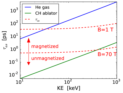
We expect a 70 T axial field to strongly magnetize the hot electrons in the low-density hohlraum gas fill, and guide them to the capsule. Recall that we inject a divergent hot electron source, so the question is whether the field confines them in space. It will not collimate them, i.e. reduce their velocity-space divergence. The electron Larmor radius , which for keV and T is m ( is the angle between and ). This is much less than the relevant plasma scale lengths. Also, the cyclotron period is 0.510 ps for T, which is much shorter than the propagation time through the hohlraum. Figure 14 plots and the time for 90∘ root-mean-square angular scatter, : for in Eq. 4. We consider two fully-ionized cases: one representative of the hohlraum fill: 0.96 mg cm-3 of He at =1 keV, and one of the ablator: 1 g cm-3 of at 200 eV. The plot shows all hot electrons are magnetized in the He, while those with 300 keV in the CH are. Even if exceeds , is much smaller than typical capsule dimensions 100’s m.
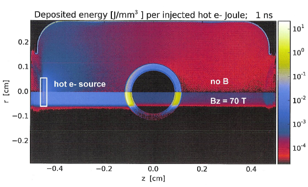
The energy deposition is shown in Fig. 15 for the ZUMA runs with no field (top half), and with a uniform 70 T field (bottom half). Table 1 lists the fraction of injected hot electron energy deposited in different regions. With no field, the hot electrons propagate essentially freely in the He gas fill. They mostly deposit in the hohlraum wall, and a small fraction deposits in the ablator. This is expected based on the solid angle subtended by these regions. With a uniform T, the hot electrons are strongly magnetized in the He gas and guided to the capsule. They mostly deposit in the ablator, out to a radius comparable to that of the source. This asymmetric preheat, occurring mostly in the poles, may drive capsule asymmetries. The energy deposited in the DT layer is x higher with the 70 T field. Whether this is a preheat concern depends on the spectrum and total energy of hot electrons produced.
The lack of deposition in high with the field means the same hot electron source produces many fewer hard x-rays. This is a diagnostics concern, since hard x-rays are generally used to deduce hot electrons on NIF. One such principal diagnostic is the FFLEX hard x-ray ( 10 keV) detector (Dewald et al., 2010; Hohenberger et al., 2014), with 10 channels filtered for different energy ranges. Energetic electrons lose energy by collisions with background electrons and by bremsstrahlung radiation. Radiation loss collisional loss, with the two equal in gold for MeV. Only electrons that deposit energy in high- material, such as the hohlraum wall, produce enough hard x-rays for FFLEX to detect. Hot electrons striking the capsule during the picket have been measured on “re-emit” experiments, where the capsule is replaced by a high- (e.g. bismuth) ball.
| Region | PICKET, | PICKET, | SRSPEAK 1, | SRSPEAK 1, |
|---|---|---|---|---|
| no B | T | no MHD | T | |
| DT gas | 6.56E-5 | 1.06E-3 (16x) | 4.32E-6 | 6.26E-5 (14x) |
| DT layer | 2.20E-3 | 0.0261 (12x) | 3.58E-4 | 2.89E-3 (8.1x) |
| CH ablator | 0.0749 | 0.696 (9.3x) | 0.406 | 0.804 (2.0x) |
| He gas | 0.0566 | 0.0646 (1.1x) | 0.223 | 0.117 (0.52x) |
| Au | 0.366 | 4.14E-4 (1.1E-3x) | 0.250 | 1.01E-4 (4.0E-4x) |
| DU | 0.428 | 4.02E-4 (9.4E-4x) | 0.0990 | 1.61E-5 (1.6E-4x) |
| total | 0.927 | 0.789 (0.85x) | 0.979 | 0.925 (0.94x) |
| Region | SRSPEAK 2, | SRSPEAK 2, | SRSPEAK 3, | SRSPEAK 3, |
| no B | T | no B | T | |
| DT gas | 1.75E-6 | 8.95E-9 (5.1E-3x) | 1.44E-6 | 5.96E-6 (4.1x) |
| DT layer | 1.37E-4 | 3.44E-6 (0.025x) | 1.19E-4 | 1.26E-3 (11x) |
| CH ablator | 0.272 | 0.105 (0.39x) | 0.327 | 0.576 (1.8x) |
| He gas | 0.229 | 0.499 (2.2x) | 0.182 | 0.248 (1.4x) |
| Au | 0.335 | 0.220 (0.66x) | 0.328 | 0.101 (0.31x) |
| DU | 0.133 | 0.0421 (0.032x) | 0.131 | 5.56E-3 (0.042x) |
| total | 0.969 | 0.866 (0.89x) | 0.968 | 0.932 (0.96x) |
7 Hot electron propagation during peak power: SRSPEAK series
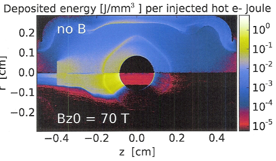
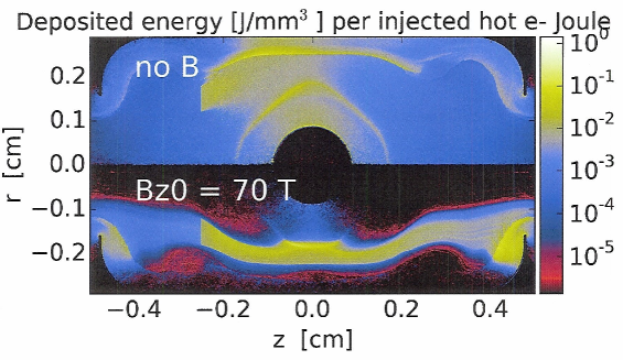
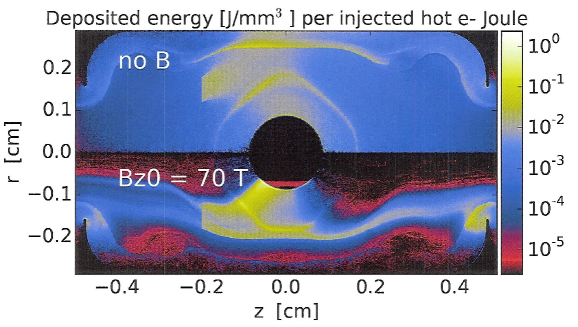
We now consider ZUMA simulations of propagation of a realistic hot electron source produced by Raman scattering on the inner beams during peak power. We use the same plasma conditions at 18 ns that were used in the CAPTEST series (i.e., a simulation of NIF shot N120321 with the full, incident laser power on each cone), along with conditions from a HYDRA run with an initial T axial field and the MHD package active. The hot electron source has a Maxwell-Jüttner energy spectrum with 30 keV. This temperature is gotten from FFLEX data at 18 ns (rise to peak power) on NIF shot N130517, which is analogous to N120321 (Robey et al., 2014). Once peak power is reached, 18 keV is consistent with FFLEX data. The injected angle spectrum is , which is directed along roughly the bisector of the two NIF inner beams at and 30∘.
We find strong sensitivity to what field lines hot electrons start on – namely, whether or not the field lines connect to the capsule. Hot electrons are injected in the three locations indicated as sources 1, 2, and 3 in Fig. 5: from to 0.06 cm at cm, and from 0.12 to 0.18 cm, at and -0.25 cm. The energy deposition vs. space is plotted in Fig. 16, and the total into various materials is given in Table 1. With no MHD, the fraction of hot electron energy deposited to DT varies from over the three sources. The field strongly magnetizes the hot electrons in the He fill gas for all three sources, as in the PICKET series of Section 6. Also like the PICKET series electrons from source 1, in the LEH, are guided to the capsule. The deposition in DT, CH, and He is greatly increased compared to the no-MHD case. For source 2, located deeper in the hohlraum and off axis, electrons are injected on field lines that do not connect to the capsule. The resulting deposition in He gas is significantly increased compared to the no-MHD case, while that into the CH ablator and especially the DT layer are reduced. The situation reverses for source 3, which is slightly closer to the capsule in than source 2. Some electrons now start on field lines that connect to the capsule, which results in much higher DT deposition. It is not presently known where in the hohlraum SRS hot electrons are produced, so we cannot say whether the field increases or decreases DT deposition. As with the PICKET series, the fraction of hot electron energy deposited in high- material is lower with the field, especially for source 1. Hard x-ray diagnostics may thus not be reliable indicators of hot electron preheat.
8 Conclusions
This paper gave results of HYDRA rad-hydro simulations with no MHD effects, and with MHD and a 70 T initial axial field. The field is essentially frozen-in to the highly conductive plasma, and gets advected with the radial expansion of the capsule and wall. This results in field lines that roughly follow contours of ablated material. The magnetic pressure is much less than material pressure. The principal hydro effect of the field is reduced electron heat conduction perpendicular to it. This gives a hotter hohlraum fill, especially in gold, and a wider channel between the capsule and equator wall. Less inner-beam absorption occurs before they reach the wall, which increases the equatorial x-ray drive. Inner-beam Raman scattering may be reduced by the hotter fill, in addition to the lower power needed to achieve a round implosion.
We also presented hot electron propagation studies with ZUMA, using plasma conditions from HYDRA. Mono-energetic test cases with plasma conditions from early peak power (18 ns) show a minimum hot electron energy of 125 keV incident on the capsule is required to reach the DT layer. The energy coupled to the layer maximizes at 13% for 185 keV electrons, and drops with energy above that. Using plasma conditions during the early-time picket (1 ns) with no field, we find a small fraction of hot electron energy from a two-plasmon-decay relevant source couples to DT. With a uniform 70 T axial field, the hot electrons are magnetized in the He fill gas, guided to the capsule, and the DT coupling increases by 12x. This may not be a preheat concern, since picket pulse shaping has been shown on NIF to significantly decrease the hot electron source. ZUMA simulations using plasma conditions at 18 ns, with a source motivated by inner-beam SRS, show an imposed field can greatly increase or decrease hot-electron coupling to DT. This depends on whether electrons are produced on field lines that connect to the capsule.
Imposed magnetic fields may enhance hohlraum performance by improving inner-beam propagation and reducing Raman scattering during peak laser power. This is in addition to the primary benefit of reducing electron-heat and alpha-particle loss from the hotspot. One concern is possible increase in DT fuel preheat due to the field guiding hot electrons to the capsule. Work is underway on a pulsed-power field generator for NIF, and we look forward to hohlraum experiments in the next few years.
We gratefully acknowledge fruitful conversations with H. F. Robey, J. D. Salmonson, C. A. Thomas, J. Hammer, and D. E. Hinkel. This work was performed under the auspices of the U.S. Department of Energy by Lawrence Livermore National Laboratory under Contract DE-AC52-07NA27344. Partly supported by LLNL LDRD project 14-ERD-028.
References
- Chang et al. (2011) Chang, P. Y., Fiksel, G., Hohenberger, M., Knauer, J. P., Betti, R., Marshall, F. J., Meyerhofer, D. D., Séguin, F. H. & Petrasso, R. D. 2011 Fusion yield enhancement in magnetized laser-driven implosions. Phys. Rev. Lett. 107 (3), 035006.
- Clark et al. (2015) Clark, D. S., Marinak, M. M., Weber, C. R., Eder, D. C., Haan, S. W., Hammel, B. A., Hinkel, D. E., Jones, O. S., Milovich, J. L., Patel, P. K., Robey, H. F., Salmonson, J. D., Sepke, S. M. & Thomas, C. A. 2015 Radiation hydrodynamics modeling of the highest compression inertial confinement fusion ignition experiment from the national ignition campaign. Phys. Plasmas 22 (2), 022703.
- Dewald et al. (2015) Dewald, E. et al. 2015 Submitted to Phys. Rev. Lett. .
- Dewald et al. (2010) Dewald, E. L., Thomas, C., Hunter, S., Divol, L., Meezan, N., Glenzer, S. H., Suter, L. J., Bond, E., Kline, J. L., Celeste, J., Bradley, D., Bell, P., Kauffman, R. L., Kilkenny, J. & Landen, O. L. 2010 Hot electron measurements in ignition relevant hohlraums on the national ignition facility. Rev. Sci. Instrum. 81 (10), 10D938.
- Döppner et al. (2012) Döppner, T., Thomas, C. A., Divol, L., Dewald, E. L., Celliers, P. M., Bradley, D. K., Callahan, D. A., Dixit, S. N., Harte, J. A., Glenn, S. M., Haan, S. W., Izumi, N., Kyrala, G. A., LaCaille, G., Kline, J. K., Kruer, W. L., Ma, T., MacKinnon, A. J., McNaney, J. M., Meezan, N. B., Robey, H. F., Salmonson, J. D., Suter, L. J., Zimmerman, G. B., Edwards, M. J., MacGowan, B. J., Kilkenny, J. D., Lindl, J. D., Van Wonterghem, B. M., Atherton, L. J., Moses, E. I., Glenzer, S. H. & Landen, O. L. 2012 Direct measurement of energetic electrons coupling to an imploding low-adiabat inertial confinement fusion capsule. Phys. Rev. Lett. 108, 135006.
- Epperlein & Haines (1986) Epperlein, E. M. & Haines, M. G. 1986 Plasma transport coefficients in a magnetic field by direct numerical solution of the Fokker-Planck equation. Phys. Fluids 29 (4), 1029–1041.
- Fujioka et al. (2013) Fujioka, Shinsuke, Zhang, Zhe, Ishihara, Kazuhiro, Shigemori, Keisuke, Hironaka, Youichiro, Johzaki, Tomoyuki, Sunahara, Atsushi, Yamamoto, Naoji, Nakashima, Hideki, Watanabe, Tsuguhiro, Shiraga, Hiroyuki, Nishimura, Hiroaki & Azechi, Hiroshi 2013 Kilotesla magnetic field due to a capacitor-coil target driven by high power laser. Sci. Rep. 3, 1170.
- Grandy (1999) Grandy, Jeffrey 1999 Conservative remapping and region overlays by intersecting arbitrary polyhedra. J. Comput. Phys. 148 (2), 433 – 466.
- Haan et al. (2011) Haan, S. W., Lindl, J. D., Callahan, D. A., Clark, D. S., Salmonson, J. D., Hammel, B. A., Atherton, L. J., Cook, R. C., Edwards, M. J., Glenzer, S., Hamza, A. V., Hatchett, S. P., Herrmann, M. C., Hinkel, D. E., Ho, D. D., Huang, H., Jones, O. S., Kline, J., Kyrala, G., Landen, O. L., MacGowan, B. J., Marinak, M. M., Meyerhofer, D. D., Milovich, J. L., Moreno, K. A., Moses, E. I., Munro, D. H., Nikroo, A., Olson, R. E., Peterson, K., Pollaine, S. M., Ralph, J. E., Robey, H. F., Spears, B. K., Springer, P. T., Suter, L. J., Thomas, C. A., Town, R. P., Vesey, R., Weber, S. V., Wilkens, H. L. & Wilson, D. C 2011 Point design targets, specifications, and requirements for the 2010 ignition campaign on the national ignition facility. Phys. Plasmas 18 (5), 051001.
- Ho (2015) Ho, D. 2015 private communication.
- Hohenberger et al. (2014) Hohenberger, M., Albert, F., Palmer, N. E., Lee, J. J., D ppner, T., Divol, L., Dewald, E. L., Bachmann, B., MacPhee, A. G., LaCaille, G., Bradley, D. K. & Stoeckl, C. 2014 Time-resolved measurements of the hot-electron population in ignition-scale experiments on the National Ignition Facility. Rev. Sci. Instrum. 85 (11), 11D501.
- Hohenberger et al. (2012) Hohenberger, M., Chang, P.-Y., Fiksel, G., Knauer, J. P., Betti, R., Marshall, F. J., Meyerhofer, D. D., Séguin, F. H. & Petrasso, R. D. 2012 Inertial confinement fusion implosions with imposed magnetic field compression using the omega laser. Phys. Plasmas 19 (5), 056306.
- Jones et al. (2012) Jones, O. S., Cerjan, C. J., Marinak, M. M., Milovich, J. L., Robey, H. F., Springer, P. T., Benedetti, L. R., Bleuel, D. L., Bond, E. J., Bradley, D. K., Callahan, D. A., Caggiano, J. A., Celliers, P. M., Clark, D. S., Dixit, S. M., Doppner, T., Dylla-Spears, R. J., Dzentitis, E. G., Farley, D. R., Glenn, S. M., Glenzer, S. H., Haan, S. W., Haid, B. J., Haynam, C. A., Hicks, D. G., Kozioziemski, B. J., LaFortune, K. N., Landen, O. L., Mapoles, E. R., MacKinnon, A. J., McNaney, J. M., Meezan, N. B., Michel, P. A., Moody, J. D., Moran, M. J., Munro, D. H., Patel, M. V., Parham, T. G., Sater, J. D., Sepke, S. M., Spears, B. K., Town, R. P. J., Weber, S. V., Widmann, K., Widmayer, C. C., Williams, E. A., Atherton, L. J., Edwards, M. J., Lindl, J. D., MacGowan, B. J., Suter, L. J., Olson, R. E., Herrmann, H. W., Kline, J. L., Kyrala, G. A., Wilson, D. C., Frenje, J., Boehly, T. R., Glebov, V., Knauer, J. P., Nikroo, A., Wilkens, H. & Kilkenny, J. D. 2012 A high-resolution integrated model of the national ignition campaign cryogenic layered experiments. Phys. Plasmas 19 (5), 056315.
- Jones & Mead (1986) Jones, R. D. & Mead, W. C. 1986 The physics of burn in magnetized deuterium-tritium plasmas. Nucl. Fusion 26 (2), 127–137.
- Koning et al. (2006) Koning, J., Kerbel, G. & Marinak, M. 2006 Resistive MHD in HYDRA using vector finite elements on 3D ALE structured hexagonal meshes. Bull. Am. Phys. Soc. 51 (7).
- Larson et al. (2010) Larson, D., Tabak, M. & Ma, T. 2010 Hybrid simulations for magnetized fast ignition targets and analyzing cone-wire experiments. Bull. Am. Phys. Soc. 55 (15).
- Lee & More (1984) Lee, Y. T. & More, R. M. 1984 An electron conductivity model for dense plasmas. Phys. Fluids 27 (5), 1273–1286.
- Marinak et al. (2001) Marinak, M. M., Kerbel, G. D., Gentile, N. A., Jones, O., Munro, D., Pollaine, S., Dittrich, T. R. & Haan, S. W. 2001 Three-dimensional HYDRA simulations of National Ignition Facility targets. Phys. Plasmas 8 (5), 2275–2280.
- Michel et al. (2015) Michel, P., Divol, L., Dewald, E. L., Milovich, J. L., Hohenberger, M., Jones, O. S., Hopkins, L. Berzak, Berger, R. L., Kruer, W. L. & Moody, J. D. 2015 Multibeam stimulated raman scattering in inertial confinement fusion conditions. Phys. Rev. Lett. 115, 055003.
- Michel et al. (2009) Michel, P., Divol, L., Williams, E. A., Weber, S., Thomas, C. A., Callahan, D. A., Haan, S. W., Salmonson, J. D., Dixit, S., Hinkel, D. E., Edwards, M. J., MacGowan, B. J., Lindl, J. D., Glenzer, S. H. & Suter, L. J. 2009 Tuning the implosion symmetry of ICF targets via controlled crossed-beam energy transfer. Phys. Rev. Lett. 102 (2), 025004.
- Montgomery et al. (2015) Montgomery, D. S., Albright, B. J., Barnak, D. H., Chang, P. Y., Davies, J. R., Fiksel, G., Froula, D. H., Kline, J. L., MacDonald, M. J., Sefkow, A. B., Yin, L. & Betti, R. 2015 Use of external magnetic fields in hohlraum plasmas to improve laser-coupling. Phys. Plasmas 22 (1), 010703.
- Moody et al. (2014) Moody, J. D., Callahan, D. A., Hinkel, D. E., Amendt, P. A., Baker, K. L., Bradley, D., Celliers, P. M., Dewald, E. L., Divol, L., D ppner, T., Eder, D. C., Edwards, M. J., Jones, O., Haan, S. W., Ho, D., Hopkins, L. B., Izumi, N., Kalantar, D., Kauffman, R. L., Kilkenny, J. D., Landen, O., Lasinski, B., LePape, S., Ma, T., MacGowan, B. J., MacLaren, S. A., Mackinnon, A. J., Meeker, D., Meezan, N., Michel, P., Milovich, J. L., Munro, D., Pak, A. E., Rosen, M., Ralph, J., Robey, H. F., Ross, J. S., Schneider, M. B., Strozzi, D., Storm, E., Thomas, C., Town, R. P. J., Widmann, K. L., Kline, J., Kyrala, G., Nikroo, A., Boehly, T., Moore, A. S. & Glenzer, S. H. 2014 Progress in hohlraum physics for the national ignition facilitya). Phys. Plasmas 21 (5), 056317.
- Perkins et al. (2013) Perkins, L. J., Logan, B. G., Zimmerman, G. B. & Werner, C. J. 2013 Two-dimensional simulations of thermonuclear burn in ignition-scale inertial confinement fusion targets under compressed axial magnetic fields. Phys. Plasmas 20 (7), 072708.
- Perkins et al. (2014) Perkins, L. J., Strozzi, D. J., Rhodes, M. A., Logan, B. G., Ho, D. D. & Hawkins, S. A. 2014 The application of imposed magnetic fields to ignition and thermonuclear burn on the National Ignition Facility. Bull. Am. Phys. Soc. 59 (15).
- Pollock et al. (2014) Pollock, Bradley, Turnbull, David, Ross, Steven, Hazi, Andrew, Ralph, Joseph, sebastian LePaper, Froula, Dustin, Heberberger, Dan & Moody, John 2014 Laser-generated magnetic fields in quasi-hohlraum geometries. Bull. Am. Phys. Soc. 59 (15).
- Regan et al. (2010) Regan, S. P., Meezan, N. B., Suter, L. J., Strozzi, D. J., Kruer, W. L., Meeker, D., Glenzer, S. H., Seka, W., Stoeckl, C., Glebov, V. Yu., Sangster, T. C., Meyerhofer, D. D., McCrory, R. L., Williams, E. A., Jones, O. S., Callahan, D. A., Rosen, M. D., Landen, O. L., Sorce, C. & MacGowan, B. J. 2010 Suprathermal electrons generated by the two-plasmon-decay instability in gas-filled hohlraums. Phys. Plasmas 17 (2), 020703.
- Rhodes et al. (2015) Rhodes, M. A., Perkins, L. J. & Logan, B. G. 2015 MAGNIFICO: a system for high-field magnetized inertial fusion at the National Ignition Facility. Submitted to IEEE Trans. Plasma Sci. .
- Robey et al. (2014) Robey, H. F., Celliers, P. M., Moody, J. D., Sater, J., Parham, T., Kozioziemski, B., Dylla-Spears, R., Ross, J. S., LePape, S., Ralph, J. E., Hohenberger, M., Dewald, E. L., Berzak Hopkins, L., Kroll, J. J., Yoxall, B. E., Hamza, A. V., Boehly, T. R., Nikroo, A., Landen, O. L. & Edwards, M. J. 2014 Shock timing measurements and analysis in deuterium-tritium-ice layered capsule implosions on NIF. Phys. Plasmas 21 (2), 022703.
- Robinson et al. (2014) Robinson, A.P.L., Strozzi, D.J., Davies, J.R., Gremillet, L., Honrubia, J.J., Johzaki, T., Kingham, R.J., Sherlock, M. & Solodov, A.A. 2014 Theory of fast electron transport for fast ignition. Nuclear Fusion 54 (5), 054003.
- Rosen et al. (2011) Rosen, M.D., Scott, H.A., Hinkel, D.E., Williams, E.A., Callahan, D.A., Town, R.P.J., Divol, L., Michel, P.A., Kruer, W.L., Suter, L.J., London, R.A., Harte, J.A. & Zimmerman, G.B. 2011 The role of a detailed configuration accounting (DCA) atomic physics package in explaining the energy balance in ignition-scale hohlraums. High Energy Density Physics 7 (3), 180 – 190.
- Salmonson et al. (2010) Salmonson, J. D., Haan, S. W., Meeker, D. J., Thomas, C. A., Robey, H. F., Suter, L. J. & Dewald, E. 2010 Assessing NIF ignition capsule performance sensitivity to hot electrons. Bull. Am. Phys. Soc. 55 (15).
- Slutz & Vesey (2012) Slutz, Stephen A. & Vesey, Roger A. 2012 High-gain magnetized inertial fusion. Phys. Rev. Lett. 108, 025003.
- Strozzi et al. (2012) Strozzi, D. J., Tabak, M., Larson, D. J., Divol, L., Kemp, A. J., Bellei, C., Marinak, M. M. & Key, M. H. 2012 Fast-ignition transport studies: Realistic electron source, integrated particle-in-cell and hydrodynamic modeling, imposed magnetic fields. Phys. Plasmas 19 (7), 072711.
- Thomas (2015) Thomas, C. A. 2015 private communication.