Numerical MHD Codes for Modeling Astrophysical Flows
Abstract
We describe a Godunov-type magnetohydrodynamic (MHD) code based on the Miyoshi & Kusano (2005) solver which can be used to solve various astrophysical hydrodynamic and MHD problems. The energy equation is in the form of entropy conservation. The code has been implemented on several different coordinate systems: 2.5D axisymmetric cylindrical coordinates, 2D Cartesian coordinates, 2D plane polar coordinates, and fully 3D cylindrical coordinates. Viscosity and diffusivity are implemented in the code to control the accretion rate in the disk and the rate of penetration of the disk matter through the magnetic field lines. The code has been utilized for the numerical investigations of a number of different astrophysical problems, several examples of which are shown.
keywords:
numerical methods, codes, magnetohydrodynamics1 Introduction
A number of numerical magnetohydrodynamic (MHD) codes have been developed for modeling plasma flows in astrophysics. Some of the most well-known codes are ZEUS (Stone & Norman, 1992), FLASH (Fryxell et al., 2000), PLUTO (Mignone et al., 2007), and ATHENA (Stone et al., 2008; Skinner & Ostriker, 2010). A number of different numerical algorithms have also been developed for the numerical integration of the MHD equations including different approaches for the spatial and temporal approximations (Brio & Wu, 1988; Cockburn, Lin & Shu, 1989; Dai & Woodward, 1994a, b; Ryu & Jones, 1995; Balsara & Spicer, 1999; Gurski, 2004; Ustyugov et al., 2009), and different algorithms for the approximate solution of the Riemann problem (Brio & Wu, 1988; Li, 2005; Miyoshi & Kusano, 2005; Miyoshi et al., 2010).
In this work, we describe a code developed by our group for the numerical modeling of astrophysical MHD flows. The code has been developed for use in several coordinate systems: (1) 2.5D axisymmetric cylindrical coordinates (); (2) 2D polar coordinates (); (3) 3D cylindrical coordinates (); and (4) a Cartesian (, ) geometry which is used to conduct tests of the ideal and non-ideal MHD modules. The difference between our code and the above-mentioned codes lies in the specifics of the astrophysical problems that we solve. Firstly, in the astrophysical regimes that we study, strong shocks (where the energy dissipation cannot be neglected) are not expected to occur. This permits the use of the entropy conservation equation instead of the full energy equation. The advantage of this approach is that the entropy conservation equation does not contain terms that differ significantly in magnitude. For example, in the energy equation, the largest terms are the gravitational energy and the kinetic energy of the azimuthal motion; these can be much larger than the internal energy and the energy of the poloidal motion near a gravitating body (for example, a planet or star). Additionally, in the vicinity of a magnetized star, the magnetic energy density can significantly exceed the matter pressure (and the energy-density of thermal energy), leading to significant errors when computing the energy conservation equation.
The different geometries have each been developed to solve a specific astrophysical problem and hence, there are slight differences in the algorithms across the various coordinate systems. The first version of the code to be developed was the axisymmetric 2.5D version; its aim is to model the interaction of accreting magnetized stars with the surrounding accretion disk. The 2D version in polar coordinates was developed later on to study the situation where planets orbit in a magnetized disk. Lastly, the 3D cylindrical version of the code was created to study intrinsically three dimensional problems such as bending waves in the disk or planets on inclined orbits. Each version of the code is based on the standard ideal MHD approach: the matter flow can be described with the one-fluid approximation.
In the 2D polar version of the code, the components of the velocity and magnetic field perpendicular to the plane of the flow are set to zero. Additionally, surface density is used instead of volume density. The formal structure of the MHD equations is the same but we make additional suggestions about the disk and the definitions of the (surface) magnetic field so that the conservation equations retain the same conservative form. Our codes use a Riemann solver based on methods developed by Miyoshi & Kusano (2005), modified to include the equation for the entropy balance.
The 2.5D axisymmetric cylindrical version of the code was developed to investigate astrophysical processes like disk accretion, magnetospheric accretion onto a magnetized star and outflows launched from the disk and star. Such MHD flows may be responsible for many the observed properties of young stars. In all of these processes, both the magnetic field of the star as well as magnetic fields induced in the magnetosphere of the star and in the accretion disk play an important role. It is often suggested that the angular momentum transport in the accretion disk is due to the magnetic turbulence associated with the magnetorotational instability (MRI) (e.g., Balbus & Hawley 1991). However, modelling this instability requires high grid resolution in the disk, which is computationally expensive. In many cases, it is more practical to allow for steady accretion by incorporating viscosity terms into the code that mimic the angular momentum transport, but do not require high grid resolution. For this reason, the 2.5D version incorporates an -type viscosity (Shakura & Sunyaev, 1973) which can be switched on or off depending on the phenomena being studied.
It is less clear how the matter in the disk interacts with magnetic field–that is, which physical processes provide efficient magnetic diffusivity in the disk. Reconnection of the magnetic field lines can provide an efficient diffusion mechanism, but the process of reconnection itself also requires some magnetic diffusivity. Since the exact mechanism is poorly understood, the magnetic diffusivity is often parametrized in the non-ideal MHD terms. This is implemented in the 2.5D version of the code as a diffusivity module, which can also be switched on or off, with the diffusivity coefficient represented in a way analogous to the viscosity.
In the 2.5D axisymmetric cylindrical version of the code, we split the magnetic field into a fixed component associated with the stellar magnetic field (for example a dipole field) and a field induced by currents in the magnetosphere and disk (Tanaka, 1994). In contrast, the magnetic field in the 2D polar version is not split into a stellar and current-induced component as the code was initially developed to study the interaction of a planet with a disk threaded by a magnetic field. In order to accurately compute the strength of the stellar gravity on the planet, the grid is allowed to co-rotate with the planet. This approach was suggested by (Kley, 1998), albeit for a different situation.
The 3D cylindrical version of the code combines the two previous versions, enabling investigations of phenomena such as planet migration in a magnetized accretion disk, accretion onto a magnetized star as well as a variety of other problems. However, there is no diffusivity module implemented in the 3D version because the 3D instabilities which cause the magnetic field to diffuse are fully modelled.
In this work, we describe our Godunov-type codes which have been implemented on several different geometries and are designed for solving non-relativistic astrophysical MHD problems. Sec. 3 describes different Godunov approaches and the approach used in our codes. In Sec. 4, we describe the different coordinate systems in detail. In Sec. 5, we describe tests of the code. Sec. 6 shows applications of these codes for different astrophysical problems and we conclude with a summary in Sec. 7.
2 The governing equations of MHD in cylindrical coordinates
Here we present the full set of ideal 3D MHD equations. Viscosity and diffusivity are implemented for specific geometries and are described separately in Sec. 4.2.2. The continuity equation in conservative form is:
| (1) |
Here are the 3D cylindrical coordinates, is the density, is the velocity, and is the time. The entropy conservation equation is:
| (2) |
where is the entropy per unit mass and is the adiabatic index. The momentum equations in the , and directions are
| (3) |
| (4) |
| (5) |
where is the magnetic field vector, is the total pressure, and is the net external force from the central star and planet. Lastly, the induction equations are:
| (6) | ||||
| (7) | ||||
| (8) |
This system of equations describes the evolution of a magnetized plasma in cylindrical coordinates.
3 Godunov type schemes
In order to numerically solve the ideal MHD equations (Eqs. 1-6), we use the Godunov method. In Godunov-type schemes, the central problem is to develop an exact or approximate algorithm to solve the Riemann problem. The construction of an exact solution to the Riemann problem is possible, but it can be numerically complex and is often computationally expensive. The procedure of exact solutions of the Riemann problem has been realized by Ryu & Jones (1995) and these exact solutions are used for the testing of our approximate Riemann solver.
Consider the one-dimensional hyperbolic system of equations in conservative form:
| (9) |
Here, is the vector of conservative variables and is the flux function which maps each conservative variable to its corresponding flux. Eq. 9 can be rewritten in the integral form of the conservation laws
| (10) |
where represents the exact solution of the Riemann problem between the left and right states and ; is a self-similar distance-time variable; is the interval along the variable at which all of the waves are localized; and and are the fluxes for the left and right states, respectively.
The Riemann problem can be approximated by a number of discontinuities, each of which satisfies the Rankine-Hugoniot jump conditions:
| (11) |
Here, is velocity of the discontinuity; are the conservative variables on either side of the discontinuity; and are the fluxes of the conservative variables across the discontinuity. In the general case, and , excluding . In this case, the condition for self-consistency of the conservation laws is evidently satisfied, while Eq. 3 for the calculation of fluxes gives , where is the flux in the interval which includes the point . If the point is located at the boundary between intervals (that is, at the discontinuity where ), then the flux can be calculated for any two adjacent states. These fluxes are the same as the ones present in the Rankine-Hugoniot jump conditions.
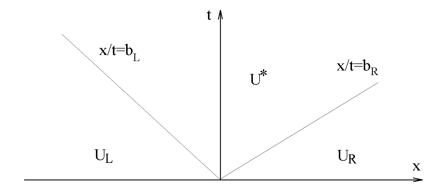
The approximate solution of the Riemann problem is represented by the vector which approximates the same conservation laws in integral form. The flux between the left and right states is approximated by
| (12) |
One of the simplest approximate Riemann solvers was proposed by Harten et al. (1983) and has two discontinuities separating three homogeneous states (as shown in Fig. 1). One discontinuity propagates to the left with velocity , while the other propagates to the right with velocity . The approximate solution is assumed to be homogeneous between these discontinuities: .
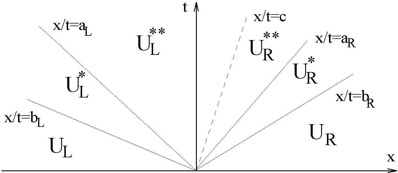
More advanced approximate Riemann solvers include two or more intermediate states (Gurski, 2004; Li, 2005; Miyoshi & Kusano, 2005).
3.1 The Miyoshi & Kusano HLLD Solver
Here, we describe the construction of our Godunov method for the equations of ideal MHD. As noted earlier, we use the entropy conservation equation instead of the energy equation. The conservative variables and fluxes in Eq. 9 take on the form:
Li (2005) proposed a modification of the HLLC approximate Riemann solver for the equations of MHD in which the transverse -components of the velocity and magnetic field are assumed to be the same in both intermediate states. For this reason, in the limit , the HLLC solver does not convert to the HLLC algorithm with a purely transverse magnetic field; this is because arbitrary jumps of the -components of velocity and magnetic field are still allowed at the contact discontinuity (as they are converted to the tangential component).
The choice of entropy conservation inhibits the modeling of MHD flows with strong shocks at which entropy production occurs. Our approximate solution has four intermediate states—the wave propagation in the HLLD algorithm is shown in Fig. 2. The initial discontinuity between the states and decays and the discontinuities appear, propagating away with velocities (the fast magnetosonic waves), (the Alfvén waves) and (the contact discontinuity). These jumps separate the initial and intermediate states (see Fig. 2). The calculation of the conservative variables and fluxes in the intermediate states is performed using the following scheme. The normal velocities across the Alfvén and contact discontinuities are assumed to be continuous
which implies
from the Rankine-Hugoniot jump conditions.
We write the Rankine-Hugoniot conditions for fast magnetosonic waves for all equations except the conservation equation for the component of the momentum. For the densities in states and , we obtain the relations
| (13) |
From Eq. 3.1 and the -component of the momentum equation we obtain
| (14) |
where
Combining Eq. 3.1 and the Rankine-Hugoniot jump conditions for the entropy, we find
To calculate the transverse components of the velocity and magnetic field in the intermediate states, we use the corresponding components of the momentum and induction equations. In the intermediate states, and , these values are determined from the jump conditions across the fast magnetosonic waves:
| (15) |
Analogously, we have
| (16) |
The values of are calculated using the same formulae, substituting the index .
The Rankine-Hugoniot jump conditions at the Alfvén waves (with ) can be solved, but only if
In the first case, we adopt , which corresponds to an Alfvén wave propagating to the left along the state . In the second case, we take , which corresponds to an Alfvén wave propagating to the right along the state .
To compute the transverse components of the velocity and magnetic field in the intermediate states , we use the fact that at the contact discontinuity
for .
Plugging these into the integral conservation laws, we find that the transverse components of the velocity and magnetic field are
where (Miyoshi & Kusano, 2005).
Note that the transverse components of the magnetic field are not necessarily equal () due to the jump conditions for the Alfvén waves in the complete system of MHD equations. Here, we remove the condition (in this case, for the component of the momentum equation) and hence lose the continuity of the magnetic pressure for the Alfvén waves.
The fluxes in the intermediate states are calculated from the jump conditions
| (17) | ||||
| (18) | ||||
| (19) | ||||
| (20) |
One does not need to calculate all of the fluxes. Rather, we determine which of the states appears at the point (in other words, which interval contains the point ) and then calculate the corresponding flux using one of the formulae (17)-(20).
In the limit , the relationships in Eq. 3.1 give the result
Similar relationships can be derived for the -component of velocity and magnetic field and for the fast magnetosonic wave which propagates to the right along . Additionally since when , the intermediate states disappear.
In the above derivations it is assumed that the inequalities
are satisfied. The case , corresponding to , has been considered above. The cases where or correspond to the switch-on waves propagating to the left or to the right, assuming or at , and are not considered. The wave velocities and are estimated as
where are the velocities of the fast magnetosonic waves, propagating along the states respectively.
3.2 Correction of wave velocities
Equations 3.1 and 3.1 show the values of the tangential velocities and magnetic fields in the intermediate states . The numerators on the right-hand sides of these formulae are non-negative, while the denominators have the form
The formula for the left state is analogous.
The physical sense of the last value is such that it should be positive because the Alfvén wave should always propagate slower than the fast MHD discontinuity. The case when this denominator is zero corresponds to the switch-on wave, in which a finite tangential field beyond the discontinuity appears from the zero tangential field in front of the discontinuity. In the approximate Riemann solver it is reasonable to retain this property (the positive sign of the denominator) in order to avoid a non-physical change of the sign of the tangential field and the appearance of a singularity as . For that, we require that the inequality is satisfied, at some . In that case, we have
This can be rewritten as
| (21) |
Comparing this relationship with that for , we conclude that if the condition in Eq. 21 is satisfied then . Analogously:
| (22) |
If the conditions in Eq. 21 and/or Eq. 22 are not satisfied (after computing using Eq. 14) then we perform a correction of and/or , choosing the fast magnetosonic velocity to be the largest and/or the smallest of the roots of Eqs. 21 and/or 22. Here, can only increase while can only decrease. We then recalculate the value , check the conditions in Eqs. 21 and 22, and if necessary, once again apply corrections to and .
3.3 Positivity
We use the equation for entropy conservation instead of the equation of energy conservation. In this case, the correction of the velocities of the fast MHD discontinuities and the positivity of the approximate solution of the Riemann solver (in the sense that the density and entropy are positive in all intermediate states) is established trivially.
3.4 Integration in time
To increase the accuracy of the numerical algorithm, we perform a two-stage Runge-Kutta integration of the equations in time. In the first stage, we calculate the values for the intermediary timestep,
Here, the fluxes are calculated using the entropy-based HLLD algorithm described above. Formally, we can write the flux calculation procedure in the form where we take the left and right states in the HLLD solver to be and .
In the second stage, the values for the full timestep, , are calculated as
The timestep is set by the Courant-Friedrichs-Levy (CFL) condition, which places an upper limit on the timestep by considering the wave crossing speeds in all cells on the grid. For our grid, the timesteps are typically limited by the strong mangetic fields in the cells near the star. For the calculation of the fluxes we use values from the intermediary timestep , reconstructed on the edges of the calculated cells:
The values are calculated at each grid cell boundary using one of the previously described approximate Riemann solvers. In order to increase the accuracy of our scheme, a slope limiter correction is applied to the primitive variables at the edges of each cell. For the sake of brevity, we define and .
Here, the top indicies are dropped and we take . In our algorithm, we reconstruct the primitive variables .
4 Numerical algorithms in cases of different geometries
4.1 Cartesian geometry
In a 2D Cartesian geometry, the MHD equations take the form
Unlike the 1D case, the vector of the conservative variables has a total of seven components. The sixth and seventh components are and , which must satisfy the divergence free condition
| (24) |
The numerical algorithm for 2D is analogous to the 1D case. The integration in time is performed using the two-step Runge-Kutta method
At the same time, . An analogous algorithm for the calculation of fluxes is also used during the second stage of the time-advancement computation.
To ensure that the magnetic field is divergence-free in 2D, we use the method proposed by Balsara & Spicer (1999). In application to problems in Cartesian coordinates, this approach is the following: if Eq. 24 is satisfied, then one can represent the and components of the magnetic field in the form
At the same time, . When the equations are discretized, the conservative variables are determined in the cells while the and fluxes, and , are computed on the sides of the cells. The corresponding components of the flux function vectors and are
where is the component of the electric field (multiplied by the speed of light). Thus, the component of the electric field is calculated twice using two different methods: the first as , and the second as . If is determined on the nodes of the grid , the components of the magnetic field can be calculated on the sides of the cells as
At the same time, the divergence-free condition will be satisfied if we require
The magnetic field in the cells are then computed from the calculated values on the cell boundaries
| (25) |
To calculate at the timestep, we determine the component of the electric field at each node. The simple variant proposed by Balsara & Spicer (1999) consists of averaging the values and over the cell sides surrounding the node at . For a homogeneous grid, this is
| (26) |
In Gardiner & Stone (2005) it was noted that this approach is inconsistent with the numerical integration algorithm in the case of 1D problems (where the solution does not depend either on or on ), and that the proposed procedure does not guarantee consistency. Gardiner & Stone (2005) propose a modified form (for homogenous grids)
| (27) |
To calculate , we use either Eqs. 4.1 or 4.1. Eq. 4.1 has applications in damping out small-scale oscillations of the magnetic field.
Thus, at each stage of numerical integration of the MHD equations, the magnetic field in the plane is calculated along the following algorithm:
-
1.
Use an approximate Riemann solver to find the components of the electric field at the sides of cells , .
- 2.
-
3.
Calculate the component of the magnetic field potential in grid nodes, .
-
4.
Calculate and .
-
5.
Using Eq. 4.1, calculate and .
4.2 Axisymmetric 2.5D cylindrical geometry
To solve the 2.5D MHD equations (with magnetic diffusivity and viscosity) in the disk, we split the different physical processes into several different modules. These are: (1) the “ideal MHD” module in which we calculate the dynamics of the plasma and magnetic field with dissipative processes switched off; the “diffusivity” modules (2) and (3) which calculate the diffusion of the poloidal and azimuthal components of the magnetic field for frozen values of the plasma velocity and thermodynamic parameters (density and pressure); and the “viscosity” module (4) which computes the viscous dissipation in the disk.
(1) In the hydrodynamic module, the ideal MHD equations are integrated numerically using an explicit conservative Godunov-type numerical scheme. In our numerical code, the dynamical variables are determined in the cells, while the vector-potential of the magnetic field, , is determined on the nodes. To calculate the fluxes between the cells, we use the previously described approximate Riemann solver.
For better spatial resolution, we perform the reconstruction of the primitive variables to the boundaries between the calculated cells. We use two types of limiters: a) the MINMOD limiter (Roe, 1986), and b) a limiter which reconstructs the function with 3rd order accuracy (which is similar to the limiter developed by Koren 1993). Integration of the equations in time is performed with a two-step Runge-Kutta method.
To guarantee a divergence-free field in the 2.5D version of the code, the -component of the magnetic field vector-potential (or magnetic flux function ) is calculated at each timestep and then used to obtain the poloidal components of the magnetic field (, ) in a divergence-free form (Toth, 2000). In other words, the condition is guaranteed to be satisfied to within machine accuracy. The calculation of is performed using either the algorithm proposed by Balsara & Spicer (1999) or the modified form proposed by Gardiner & Stone (2005).
(2) In the module where the diffusion of the poloidal magnetic field is calculated, we numerically integrate the equation for the -component of magnetic field vector-potential (or magnetic flux function ), using an explicit approximation.
(3) In the module where the diffusion of the azimuthal component of the magnetic field and (4) the viscous stresses are calculated, we add diffusive terms which approximate the corresponding spatial derivatives to the fluxes calculated by the ideal MHD module.
The ideal and diffusivity modules are verified separately using a number of standard tests. The setup and results of these tests are discussed in Sec. 5.
4.2.1 Ideal MHD module
The ideal MHD equations in the axisymmetric cylindrical geometry are derived from the full set of 3D MHD equations by requring that (see Sec. 4.3). The equations are written in a form which does not have singularities on the right hand side. For the and components of the equation of motion and component of the induction equation, we substitute the operator , representing divergence operator in cylindrical coordinates. As a result, the component of the equations of motion takes on the form of angular momentum conservation while the component of the induction equation takes on its typical form.
In discretizing the cylindrical MHD equations, we take into account the fact that near the symmetry axis (where ), different variables have different asymptotic behavior. For example, the values as whereas the values scale with . Analogous behavior is shown by the fluxes corresponding to these variables. In particular, in the approximation of the component of the equation of motion (the angular momentum equation), we multiply the fourth equation (Eq. 2) by and integrate it along and in the limits of the calculated cell . The equation is then rewritten in the form and , where and weakly depend on . Here we have dropped the indices on and .
We have
Next
where
| (28) |
Analogously,
Thus, the angular momentum conservation equation for the cell has the form:
| (29) |
It is clear that this approximation of the operator and more precisely of the multiplier , significantly differs from analogous terms (for example, of ) only in the vicinity of the symmetry axis.
The flux densities and , which are used in Eq. 2, are calculated using the 1D algorithm for the approximate solution of the Riemann problem.
4.2.2 Viscosity and diffusivity
Here we discuss the treatment of viscosity and diffusivity. We use equations of motion in cylindrical coordinates in the form:
| (30) |
The stress tensor consists of an ideal part :
which is used to derive the momentum equations in Eqs. 2, 2 and 2, and a viscous part which takes into account small-scale turbulent velocity and magnetic field fluctuations.
We assume that the stress due to the turbulent fluctuations can be represented in the same way as the collisional viscosity by substituting in the turbulent viscosity coefficient. The components of the tensor in axisymmetric cylindrical coordinates are:
| (31) |
Here is the angular velocity of the plasma and is the dynamical turbulent viscosity. In 3D, we only consider the and components of the stress tensor as these are expected to be dominant; similarly, in 2D polar coordinates, we only consider the component.
Separating out the viscous stress in the component of the momentum equation gives
| (32) |
where and are components of the inviscid part of the stress tensor.
We assume that the plasma has a finite magnetic diffusivity. That is, the matter may diffuse across the field lines. We also assume that the finite diffusivity of the plasma is due to the small-scale turbulent fluctuations of the velocity and the magnetic field. The induction equation averaged over the small-scale fluctuations has the form
| (33) |
Here, and are the averaged velocity and magnetic fields, and is electromotive force connected with the fluctuating fields.
Since the turbulent electromotive force is connected with small-scale fluctuations, it is reasonable to suppose that it has a simple relation to the ordered magnetic field . If we neglect the magnetic dynamo -effect (Moffat, 1978), then , where is the coefficient of turbulent magnetic diffusivity. Equation (33) now takes the form
| (34) |
We should note that the term for formally coincides with Ohm’s law
The coefficient of turbulent electric conductivity .
To calculate the evolution of the poloidal magnetic field it is useful to calculate the -component of the vector-potential or magnetic flux function . Due to the assumed axisymmetry,
| (35) |
Substituting into the induction equation gives the equation for the component of the vector-potential
| (36) |
The azimuthal component of the induction equation gives
| (37) |
The viscosity and magnetic diffusivity lead to dissipation of the kinetic and magnetic energies, conversion into thermal energy and a corresponding increase of the entropy. In our simulations we have neglected viscous and Ohmic heating. We have also neglected radiative cooling. Thus, the main effect of the viscous terms is the transport of angular momentum outward which allows matter to accrete inward to the disk-magnetosphere boundary. The main effect of the diffusion terms is the transport of matter through magnetic field lines.
The dissipative terms and, are incorporated into the numerical algorithm by way of a flux correction in the finite-difference equations. The modified fluxes are included in the angular momentum conservation equations, and the modified fluxes (components of the poloidal electric field) are included into the component of the induction equation. The approximation of the viscous stresses takes the form:
The approximation of the poloidal electric field has the form:
Here, and are the and components of electric field, and are the same components calculated in the approximation of the ideal plasma conductivity using the algorithm described above, .
The coefficients of the dynamical viscosity at the boundaries between calculated cells are calculated according to . Here, and are the coefficients of the dynamical viscosity in the grid cells. Analogously, we calculate and the coefficient of the dynamical viscosity at the boundaries between cells.
The azimuthal component of the electric field, responsible for the evolution of the magnetic flux function , is approximated using a special method. The azimuthal component of the turbulent electric field is presented in the form
and approximated by
| (38) |
4.3 3D cylindrical geometry
We have also developed a fully three dimensional version of the code in cylindrical coordinates. To calculate the fluxes between cells, we use the HLLD method as in the 2.5D code (Miyoshi & Kusano, 2005). To correct the fluxes, we use the MINMOD flux corrector, which is applied on the primitive variables . To integrate the equations in time, we use the two-step Runge-Kutta method.
The main differences between the 2D and 3D codes lie in the algorithm which ensures that the magnetic field is divergence-free. Namely, the divergence-free condition is guaranteed by calculating the components of the magnetic field on the sides of cells from the induction equation:
The components of the electric field are calculated at the edges of the cell as in the axisymmetric case. For example:
where the values on the right hand side are the corresponding fluxes calculated by the Riemann solver: is determined between cells and and so on.
After calculating the electric field components, the magnetic field components at the sides of cells (for example, at ) are calculated using the formula
The other components and are calculated in a similar fashion. This ensures that the magnetic field is divergence-free (so long as the field is initially divergence-free at the beginning of the simulation). As a next step, the magnetic field in the cells is calculated from the values on the cell boundaries:
4.4 2D polar geometry
To describe the interaction of the accretion disk with a planet in the presence of a magnetic field, we use a model which describes the processes in terms of surface variables (density and pressure). The equations for this model are obtained by integrating the three-dimensional MHD equations along the direction which is perpendicular to the disk plane. For simplicity, we assume that the components of the velocity and the magnetic field are zero and there is no field outside the disk.
The governing equations are derived from the ideal MHD equations (Eq. 6) by integrating in the vertical direction:
| (40) |
| (41) |
| (42) |
| (43) |
Here is the surface density; is the surface pressure; is the -averaged analog of the mangetic field; is an analog of the entropy; , and are the components of the force per unit surface area acting from the planet on the disk matter. These resemble the standard form of the 2D equations where the derivative in the 3D equations is set to 0.
The induction equations take on the form
| (44) |
| (45) |
Here, is the “magnetic thickness” of the disk, which is the characteristic scale for the magnetic field distribution in direction. This scale is not identical to the disk height which characterizes the distribution of the density and pressure in the disk. We take to be the same across both equations. Since the magnetic field in the disk is unlikely to change sign in the vertical direction, the approximation seems to be reasonable. The next suggestion which helps to close the system of equations is in the dependence of the magnetic thickness of the disk on the radius. In particular, if we assume is constant, then the induction equations will also take the standard form (in the same sense that ). To calculate the magnetic field and volumetric density and pressure from the integrated values, we assume a disk thickness at some characteristic radius and back out the volumetric terms.
5 Tests of the Code
We have performed multiple tests of the code across different grid geometries. Below we show two examples of such tests. In the first, we test the ideal MHD module (with the viscosity and diffusivity modules switched off). In the second, we test the diffusion module separately.
5.1 Test of the ideal MHD module
5.1.1 The 2D rotor problem
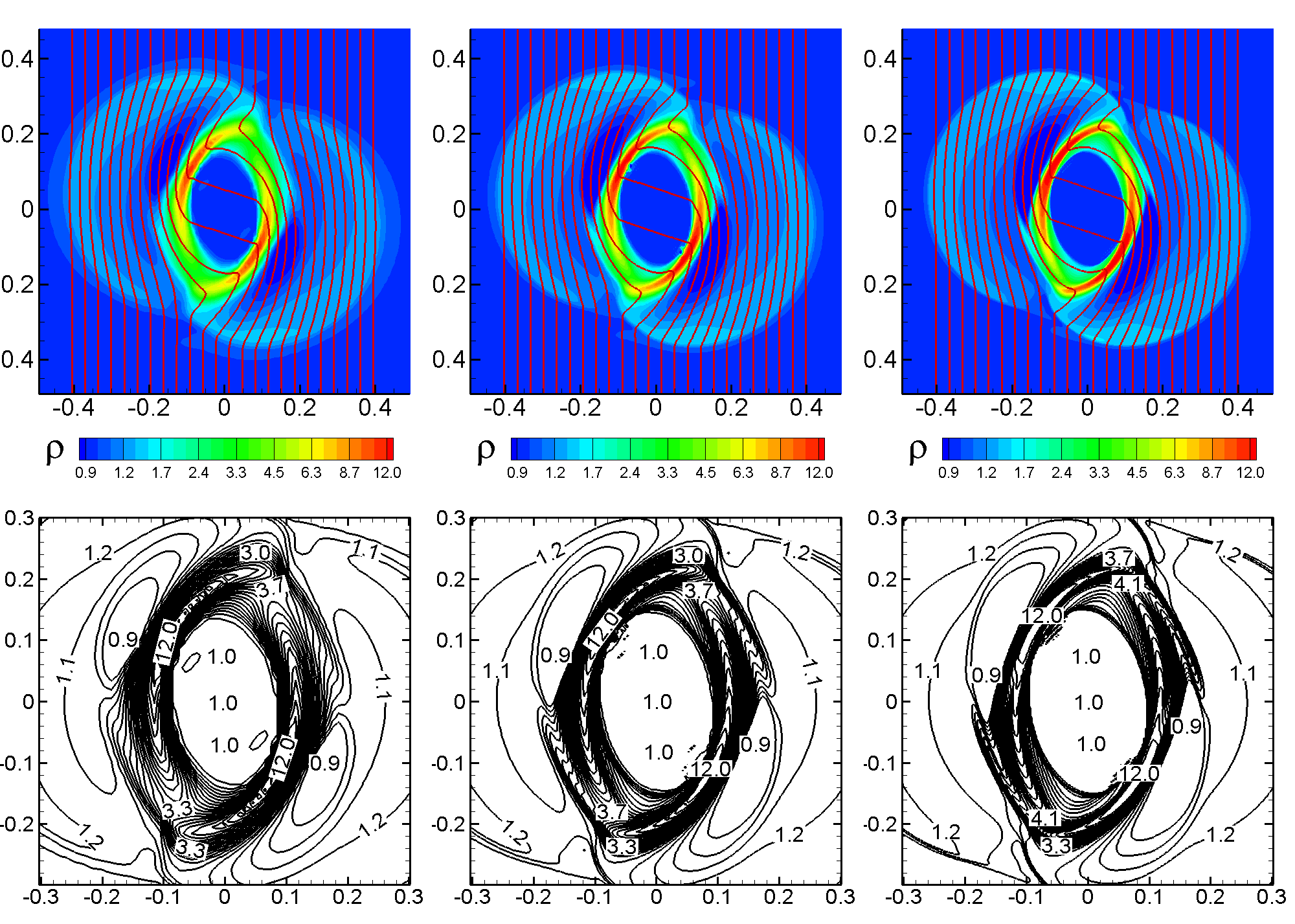
The first test is the standard “rotor problem” in Cartesian coordinates. This test has been used by a number of authors for testing MHD solvers which use the energy equation (Balsara & Spicer, 1999; Toth, 2000). We use this test to check the ideal MHD module of our code (with viscosity and diffusivity switched off).
The ideal MHD equations are solved on a regular Cartesian grid in the region , with grid sizes , where for the three different tests. At the beginning of the simulations, , the pressure in the region is constant, , and the magnetic field is homogeneous, , . In the center, there is a circle of higher-density matter () with radius (where the radius is ). The matter in the inner circle initially rotates as a solid body with angular velocity . For , the density is and the matter is at rest. In the ring in between these two regions , the density and velocity are linearly interpolated between the values at and .
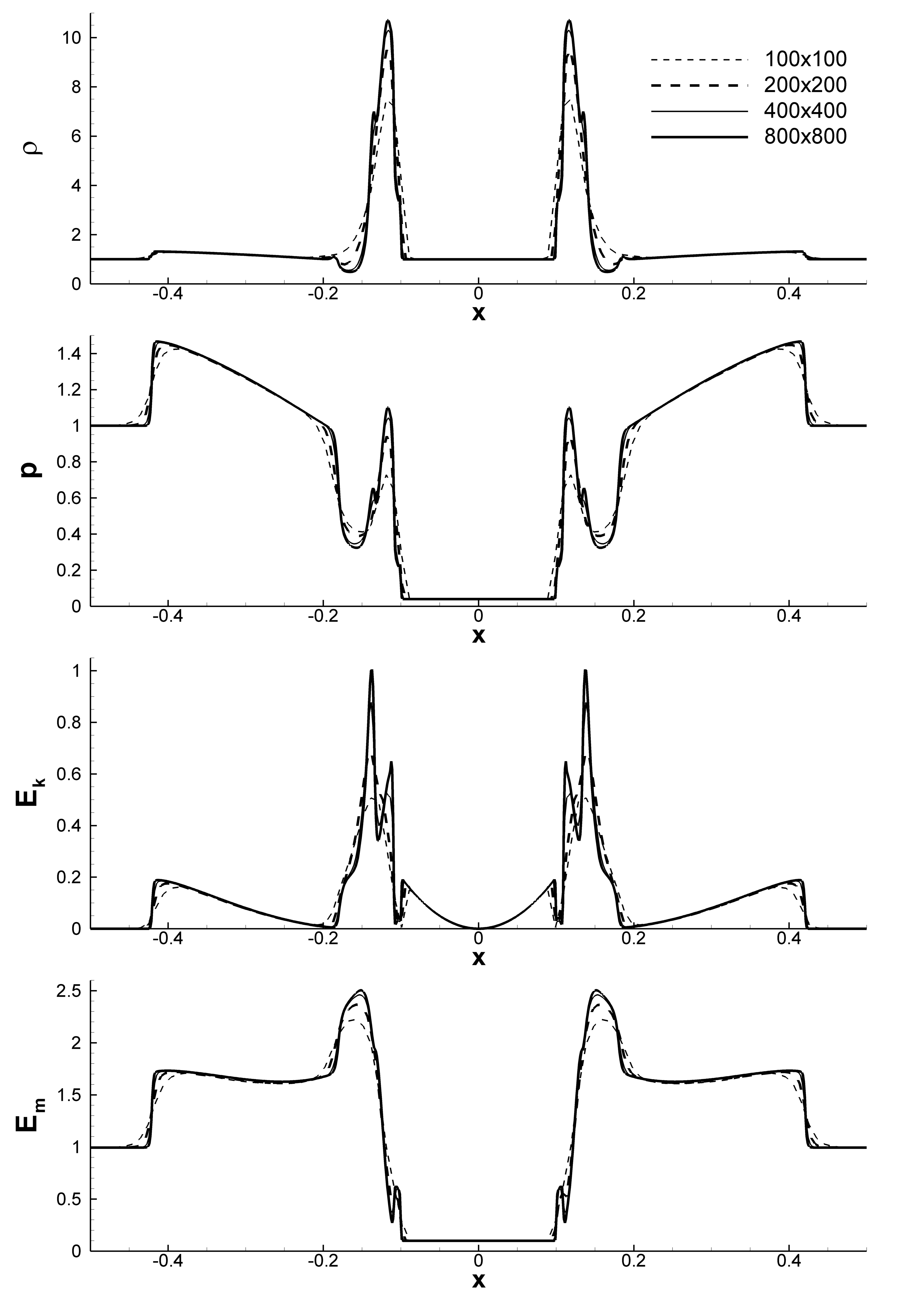
The equations of ideal adiabatic MHD are solved with the previously described Godunov-type scheme. The timesteps are calculated from the condition where is the maximum timestep allowed by the Courant-Friedrichs-Levy (CFL) condition. The results of the simulations at are shown in Fig. 3. Evidently, the density and the field line distribution is very similar in all three of our cases. The bottom panels of Fig. 3 show selected streamlines with numbers which clearly show the similarity of the results across the various grid sizes. Fig. 4 shows slices along the -axis for the density, pressure, kinetic energy, and magnetic energy for each of the three grid sizes in addition to a high resolution grid with . At the highest resolutions, the models are nearly indistinguishable and the convergence of the results is evident.
5.1.2 2D Low-type analytical solutions
To test the ideal MHD module, we also compare our numerical calculations with analytic solutions found by Low (1984). One of them has been used in Stone & Norman (1992) for testing the corresponding module of the ZEUS code. It is convenient to write these solutions in spherical coordinates (as we will do below), and then to convert them to cylindrical coordinates.
These solutions are self-similar and assume that the magnetic flux function has a dependence on the time and radial coordinate of the form . Here is a time-dependent scaling parameter and is the self-similarity radius. The velocity has only a radial component (in the spherical coordinate system) which depends linearly on the radius. The function satisfies the equation , and the magnetic flux function satisfies the Grad-Shafranov equation. The other variables are connected with and and their derivatives by algebraic relationships. The first solution proposed by Lou (1998) and used for testing does not have an azimuthal component of the magnetic field. The second solution used in Stone & Norman (1992) has a non-zero azimuthal magnetic field , but the motion of the plasma is inertial.
In the first solution, Lou (1998) chose growing solutions of the function
| (46) |
The magnetic flux function has the form
The poloidal components of the magnetic field are calculated along the known formulae
The initial pressure and density are
And the radial velocity is given by:
We take the following parameters for the problem: , the adiabatic index is .
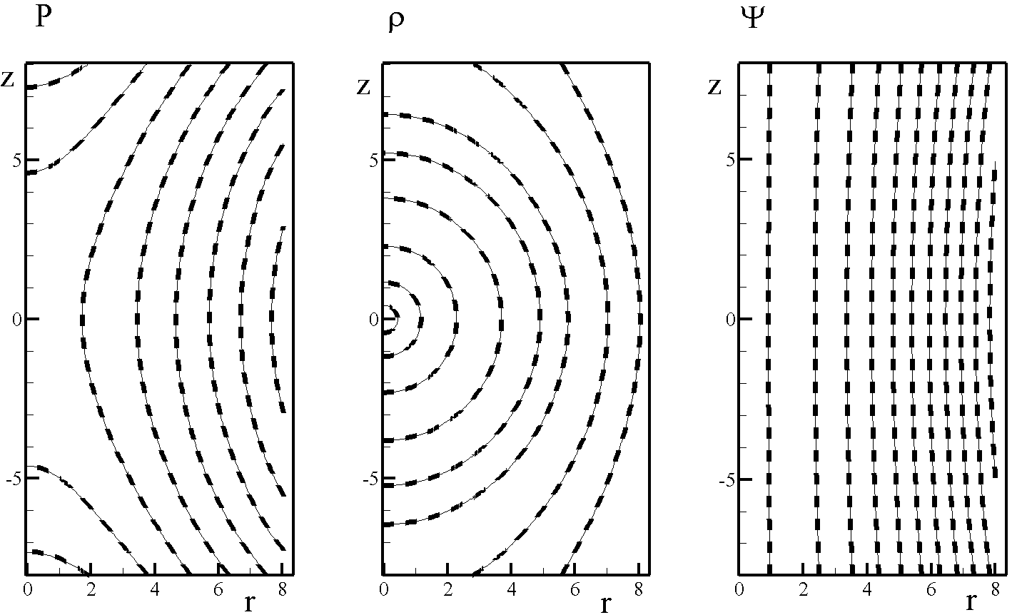
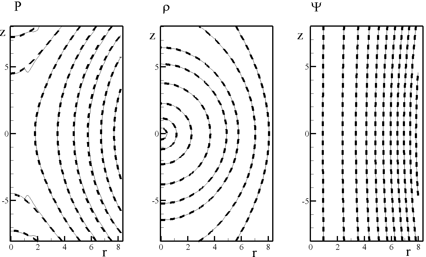
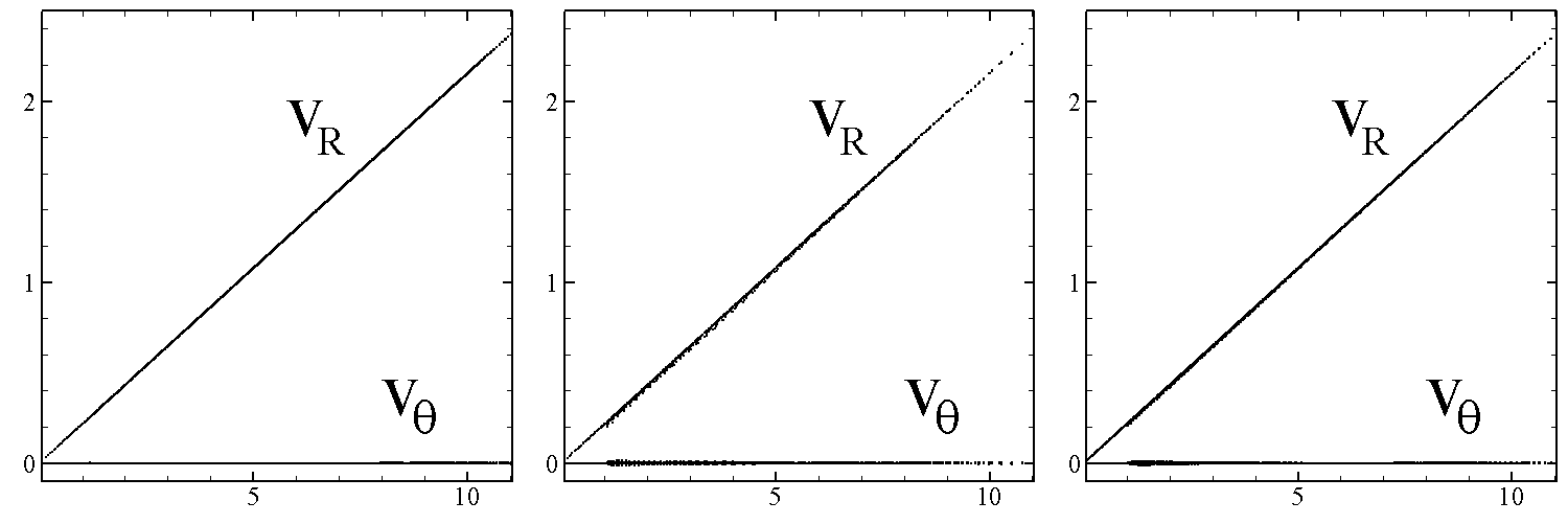
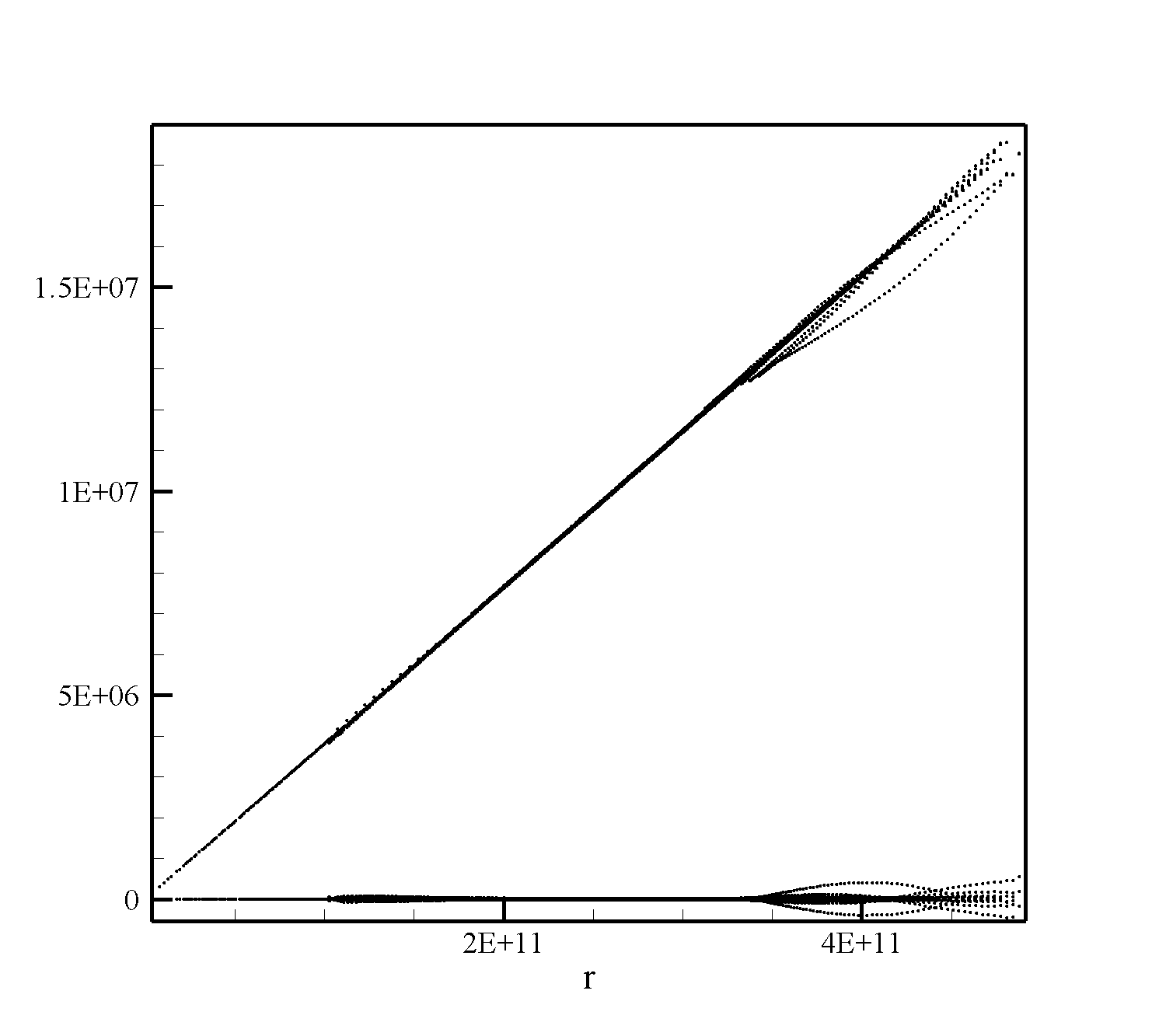
The solution is numerically computed over the region , with a rectangular region, , excised from the simulation. We use two grids: a homogeneous grid, with , and an inhomogeneous grid, . In both cases, the excised rectangular region is homogeneous, with dimensions , though values are not computed in this region. Thus, the cell sizes of the homogenous grid are and . For the inhomogeneous grid, the grid size is increased in a geometrical progression with the power . The integration time-step has been chosen automatically such that . The function is determined by numerically integrating Eq. 46 with the initial condition at sufficiently fine grid resolution. As an initial condition, the analytical solution is used with the parameter . For boundary conditions, we also use the analytical solution for all variables with the parameter corresponding to the moment of time. The simulations were performed up to the moment of time when . Fig. 5 and Fig. 6 from left to right show the pressure, density and magnetic flux function at the moment of time when the scaling parameter is . Fig. 5 shows the result of the simulations on a homogeneous grid, while Fig. 6 shows the results for the inhomogeneous grid. In all of the plots, the solid line shows the numerical solution and the dashed line shows the analytical solution. Fig. 7 shows the radial and transverse components of the velocities as a function of the spherical radius. One can see that the velocity is directed along the radial direction and is proportional to the radius with the high accuracy.
In the second solution (Stone & Norman, 1992) the scaling factor linearly depends on time, . In this case, the magnetic flux function has the form
The poloidal components of the magnetic field (in spherical coordinates) can be calculated using the analytic solution
The azimuthal component of the magnetic field is
| (49) |
The density and pressure are given by
The radial velocity is simply .
The parameters of the problem are assigned the following values: , the adiabatic index is .
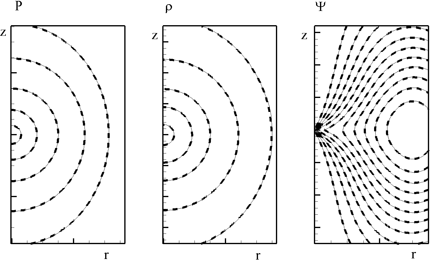
The equations of ideal MHD are integrated in the region , , where an inner rectangle with size , has been excised from the region. We use the homogeneous grid , and the grid in the excised region is . Thus, the cell size is and . The time-step is chosen automatically such that . As an initial condition, we take the analytical solution described above for . We use the analytical solution for the boundary conditions, taking the parameter to correspond to the moment of time. The calculations are done up to the moment when the scaling parameter reaches the value . As before, Fig. 8 and Fig. 9 show the results of simulations at the moment when the scaling parameter becomes equal to .
5.1.3 The 3D rotor problem
As with the 2D code, we test the 3D code with the rotor problem. The 3D MHD equations are solved numerically in the cylindrical region , and the initial conditions are determined using the same initial conditions as in the 2D test. In the beginning of the simulations, , the pressure in the region is constant, , and the magnetic field is homogeneous, , . In the center there is a circle with radius where the matter density is and the matter rotates as a solid body with angular velocity . At , the density is and the matter is at rest. In the ring , the density and velocity are linearly interpolated between those at and .
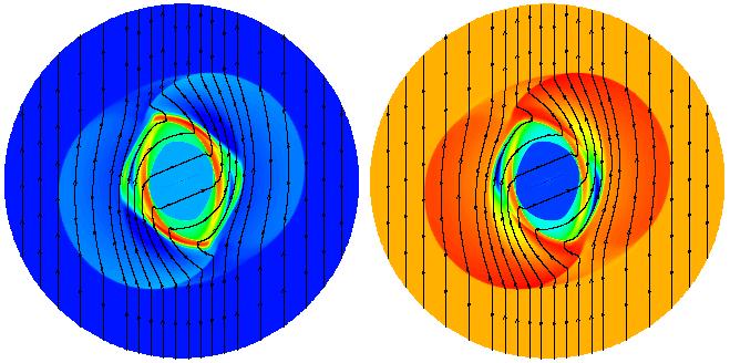
In the test we use a homogeneous grid with . The integration time-step is chosen automatically in such way that . The results of the simulations at time are shown in Fig. 10. One can see that the density, pressure and the field line distributions are very similar to 2D case.
5.1.4 3D Low-type analytical solution
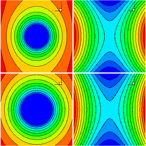
To test the ideal MHD module, we also use the analytical solution described in Sec. 5.1.2. Calculations were performed in the cylindrical region for a grid . Results of simulations are shown in Fig. 11. The color background shows pressure distribution (left panel) and density (right panel). The lines show corresponding analytical solutions.


5.2 Test of the diffusivity module
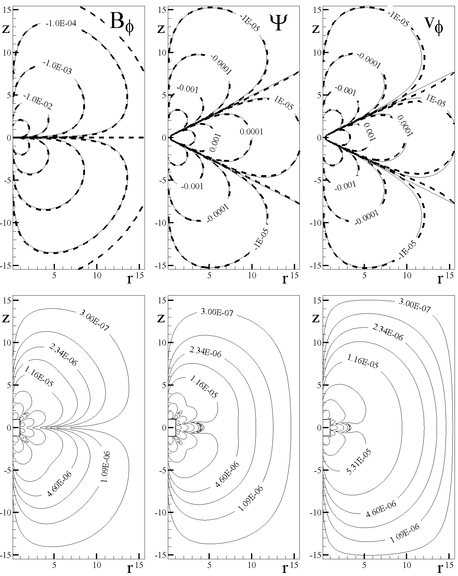
Here we test the diffusivity module of the code. For this we switch off the hydrodynamic fluxes and the corresponding right-hand side terms in Eqs. 36 and 37 and integrate these equations numerically in the region , with the rectangular region , excised from simulations.
| (50) | ||||
| (51) | ||||
| (52) |
The solutions for the magnetic flux function and azimuthal velocity are symmetric about the equatorial plane while solutions for the azimuthal component of the magnetic field are antisymmetric. All solutions go to zero at the symmetry axis
We can find particular solutions of Eqs. 50–52 by the method of variable separation in spherical coordinates. For , Eq. 50 in spherical coordinates is
| (53) |
For testing we choose the following solutions of Eq. 53:
| (54) | ||||
| (55) | ||||
| (56) |
where and are constants, is the spherical radius, and is the polar angle.
The equations for the magnetic flux function and the -components of the velocity and magnetic field are integrated numerically using our 2.5D code (with the switched-off hydrodynamic fluxes and zero right hand side terms). We use the same grid geometry as in the main simulations; that is, cylindrical coordinates with a non-equidistant grid in both directions.
For the test, we take a grid of , and also a finer grid with . We also take the inner and outer radii (in the direction) of the simulation to be and . For these boundaries we set and to be equal to the analytical values determined by Eqs. 54-56. The initial conditions correspond to the exact solutions of Eqs. 54-56 at . The constants and in these equations are chosen so that the solutions at the inner boundary are of the order of unity. We use , and integrate the equations up to .
| Grids | ||||
|---|---|---|---|---|
The top panels of Fig. 12 show the result of the diffusivity test for the -component of the magnetic field, the vector potential, and the -component of the velocity. The solid lines show the numerical solution of Eqs. 50-52, which are obtained by integrating the equations using our code until . The dashed lines show the exact solutions given by Eqs. 54-56. Evidently, the numerical and analytical solutions are nearly identical. The bottom panel shows the absolute errors for each function. One can see that the error is very small everywhere, taking into account the fact that the maximum value of all the functions, . The error increases towards the star because the value of the functions also strongly increases towards the star. We perform similar simulations and analysis for finer grid resolutions . Table 1 shows the maximum absolute errors, , , and . One can see that for the finer grid (dimensions ), this error is and times smaller compared to the coarsest grid (dimensions ). This confirms the convergence of the numerical solution towards the analytical solution. Similar comparisons for the component give factors and , which also show convergence. Similar comparisons for the component give factors and , which also show convergence.
6 Examples of Astrophysical Simulations
The codes discussed in this paper have already been used to study a variety of different astrophysical problems. Below, we show a few examples of calculations with the code in both 2D and 3D geometries.
6.1 Counter-rotating accretion disks: 2.5D hydro simulations in cylindrical coordinates
The hydrodynamic version of the code in 2.5D cylindrical coordinates was used to study counter-rotating accretion disks (Dyda et al., 2015). The simulations show that the interaction between two counter-rotating regions of the disk strongly depends on the value of the viscosity coefficient which varies from up to . The simulations show that in counter-rotating disks, the accretion rate may be increased by a factor of .
The problem is set up such that the inner region of the disk orbits the star in one direction while the outer part orbits in the opposing direction (see Fig. 13, top panels). The simulations were performed for a viscosity parameter of . Initially, the boundary between the counter-rotating regions of the disk is sharp. When the simulations start, the oppositely directed regions of the disk start interacting due to viscosity, leading to annihilation of the angular momentum at the interface. This matter, which has lost some of its centrifugal support, begins to accrete rapidly due to the unbalanced gravitational force. This leads to a hundred-fold increase of the accretion rate compared with a disk which does not have a counter-rotating component. The simulations also show that the component of the stress tensor, , dominates the angular momentum transport in the disk.
We also study the case where a clump of counter-rotating matter is allowed to interact with the top of the disk (see Fig. 13, bottom panels). We find that a part of the disk matter loses angular momentum through viscous interactions with the counter-rotating clump and is quickly accreted onto the star. Analysis shows that in this case, three components of the viscosity tensor , and contribute to the angular momentum transport.
6.2 MRI-driven accretion onto a magnetized star: 2.5D MHD simulations in cylindrical coordinates

The code has also been utilized to study accretion onto a magnetized star from a turbulent accretion disk in 2.5D cylindrical coordinates (Romanova et al., 2011). A sample of the results are shown in the right panel of Figure 14. The turbulence present in the disk is driven by the magneto-rotational (MRI) instability (e.g., Balbus & Hawley 1991). Simulations were performed for different magnetospheric radii and different initial values of the plasma parameter in the disk, which varied from to . The dynamical range of initial densities between the disk and corona was . Inside the magnetosphere, the dipole magnetic field varies as and the magnetic pressure varies as . In the regions of high magnetic pressure, the matter pressure and density become very low, thereby limiting the simulation timestep and slowing the calculation. To overcome this difficulty, we require: , where ; in other words, we require that the matter pressure does not fall below a certain fraction of the magnetic pressure. In the grid cells where the matter pressure becomes smaller than this value, it is adjusted to be . We then recalculate the density to be thermodynamically consistent. In cases of large magnetospheres, this leads to slightly enhanced matter density and pressure near the star. However, this does not change the physics of the magnetosphere because the magnetic pressure is still times higher than the matter pressure, and therefore the physics of the disk-magnetosphere interaction is described correctly in the sense that the magnetosphere is strongly magnetically-dominated. In other parts of simulation region, no floor density or pressure is added.
The grid is compressed towards the disk midplane and towards the axis with the goal of having higher grid resolution in the disk and near the star. The left panel of Figure 14 shows a typical grid used in this study with cells in the radial direction and cells in the axial direction. The number of grid cells covering the disk in the vertical direction (in the middle of the disk) is about 200, and the MRI-unstable modes are well-resolved even in cases of a small-scale turbulence.
For this study, the viscosity or diffusivity terms are not enabled. The disk matter is loaded onto the magnetic field lines of the magnetosphere due to reconnection or due to the small numerical diffusivity which is present in the code.
6.3 Propeller outflows from the disk-magnetosphere boundary: 2.5D MHD simulations
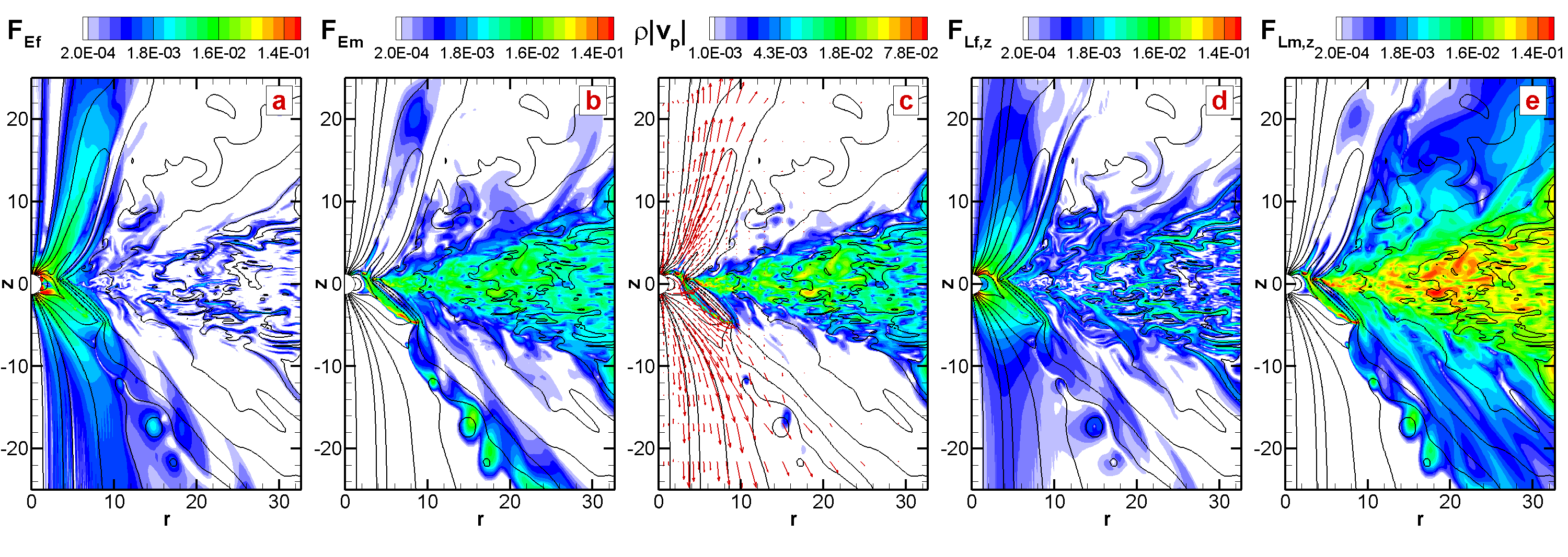
Another problem which has been studied using this code is that of disk accretion onto a magnetized star rotating in the propeller regime (Lii et al., 2014). In the propeller regime of accretion, the magnetosphere of the star rotates more rapidly than the inner disk; the angular momentum imparted on the disk by the magnetosphere can push the disk away or drive outflows from the disk-magnetosphere boundary (e.g., Illarionov & Sunyaev 1975; Lovelace et al. 1999). As in the previous study (Sec. 6.2), the angular momentum transport in the disk is mediated by the MRI-driven turbulence.
The large centrifugal barrier at the disk-magnetosphere boundary inhibits direct accretion onto the star. Rather, the disk matter accumulates at the disk-magnetosphere boundary until it compresses the magnetosphere inward of the corotation radius and accretion can proceed. The result is a burst of accretion in which part of the matter accretes onto the star and part is launched as a short-lived magneto-centrifugal wind. There is also a secondary low-density wind which flows out along field lines anchored to the surface of the star. In the latter component of the winds, the matter is launched rapidly, resulting in low density regions near the star.
In order to prevent the density (and simulation timestep) from becoming too small, we implement a floor density condition. That is, we fix the minimum density in the simulation region to be , effectively adding a small amount of matter whenever the density drops below a certain threshold. We track the amount of matter that is added, and find that it is much smaller than the matter flux in the disk and in the wind. We also implement the matter pressure floor condition for matter pressure inside the magnetosphere (see Sec. 6.2).
As a word of caution: for relatively large values of , the matter which is added to maintain the floor pressure can have a tendency to flow out of the super-Keplerian magnetosphere due to centrifugal forces, thereby forming an artificial outflow. However, for low enough values of (up to ), no artificial outflows from the inner magnetosphere were observed.
Fig. 15 shows matter flux and also energy and angular momentum carried by the matter and the magnetic field (see details and description of fluxes in Lii et al. 2014). The axisymmetric grid is in cylindrical (, ) coordinates with mesh compression towards the disk and towards the -axis such that there are a larger number of cells in the disk plane and near the star. In the models presented here, we use a non-uniform grid with dimension cells. corresponding to a grid that is 66 by 140 stellar radii in size. At , the number of grid cells which cover the disk in the vertical direction is about 200.
At the disk-magnetosphere boundary, 3D instabilities may cause the disk matter to penetrate through the magnetic field lines into the magnetosphere. Since these instabilites are intrinsically three dimensional, they are not modeled in the current axisymmetric 2.5D simulations. To mimic these processes, we implement diffusivity near the star using the diffusivity module described in Sec. 4.2.2. To prevent modifications to the overall disk accretion rate, the diffusivity is only enabled near the disk-magnetosphere boundary. We study the disk-magnetosphere interaction in this region for different diffusivity parameters . We find that for larger values of , the disk matter penetrates through the magnetosphere more rapidly causing most of the accreting matter to be ejected into an outflow.
6.4 Migration of a planet in the magnetized disk: 2D MHD simulations in polar coordinates
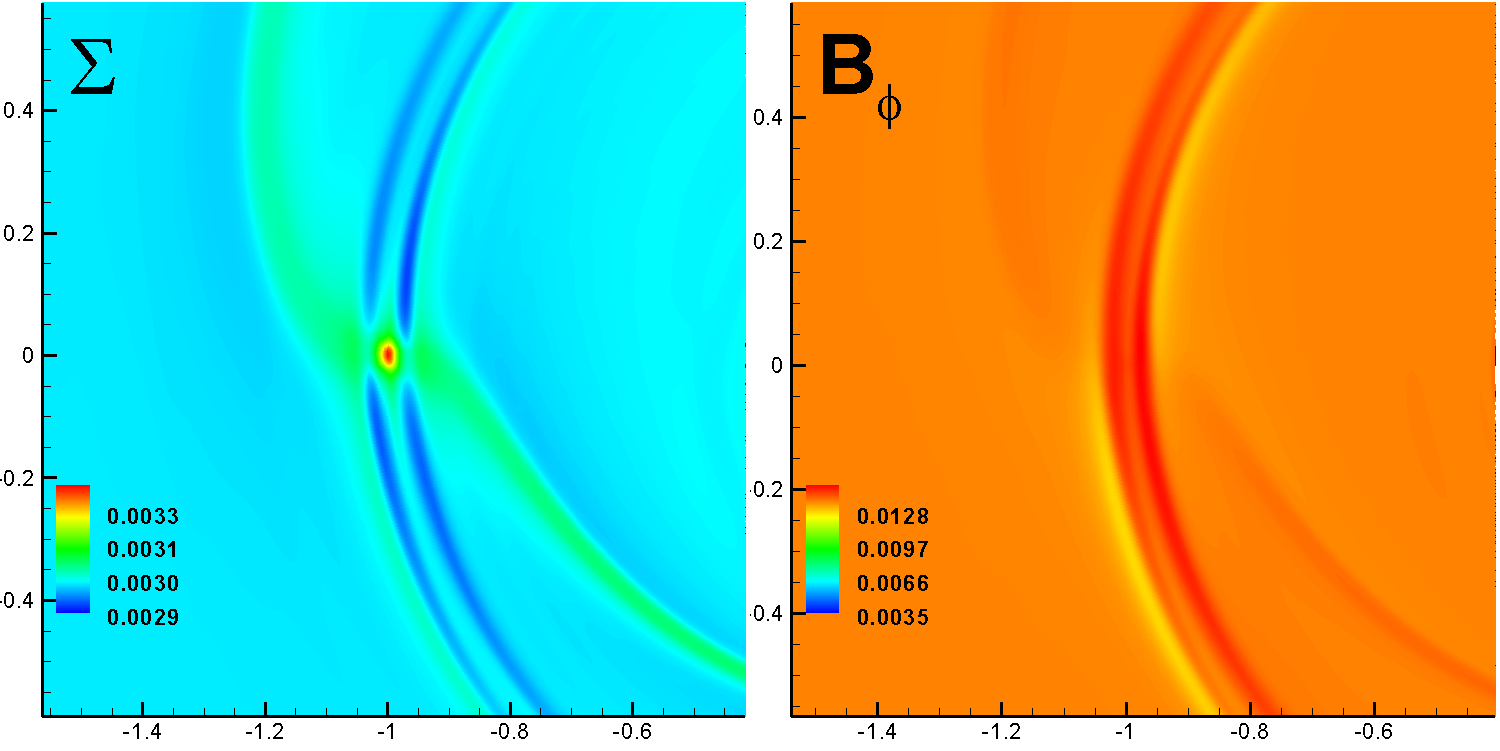
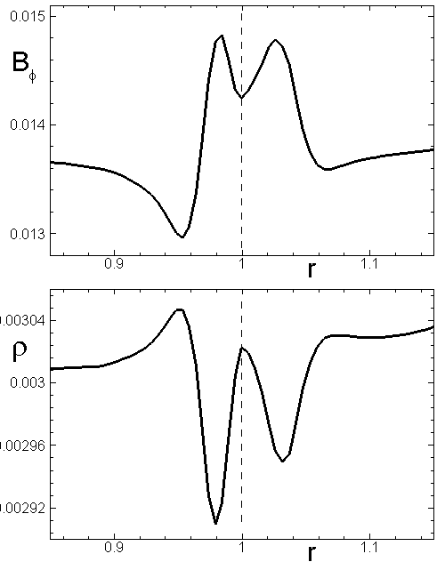
A version of the code in 2D polar coordinates has been used to model the migration of a planet through a magnetized disk (Comins et al. 2015, in prep.). In a test version of this problem, we followed the approach by Fromang et al. (2005) which used two different codes to solve this problem (FARGO and another code). Our initial conditions are almost identical to those taken by Fromang et al. (2005): the planet’s mass is 5 Earth masses; the disk has a constant surface density distribution; the initial magnetic field has only an azimuthal component, , which scales with radius as where ; and lastly, the disk is locally-isothermal. We take for the adiabatic index to mimic a locally-isothermal disk. The size of simulation region is and , and the grid and . The grid is stretched in the radial direction such that the grid cells are almost rectangular in all parts of the simulation region. The magnetic resonances are resolved at 12 grid cells in the radial direction.
Our simulations confirm the results obtained by Fromang et al. (2005). Namely, that if the plasma parameter is of order unity, then the magnetic resonances can be more important than the Lindblad resonances (which lead to inward migration) and the migration can be stopped if the radial gradient of the azimuthal magnetic field is sufficiently large. Fig. 16 shows the density distribution where the magnetic resonances are observed as azimuthally-stretched density depletions near the planet (see left panel). The middle panel shows that in the region of magnetic resonances, the magnetic field is enhanced. The right panel shows a radial cut of the density and magnetic field along the planet’s radial vector. We find that at the migration is inward; in contrast, for steeper density profiles ( and ) the planet migrates outward. This is in accord with the results obtained by Fromang et al. (2005), who find that the inward migration consistently slows and reverses direction as increases.
6.5 Migration of a planet in non-magnetized laminar disk: 3D hydro simulations in cylindrical coordinates
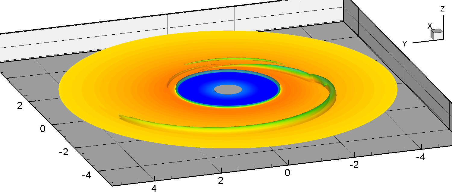
A version of the 3D code in cylindrical coordinates has been used to model the migration of a planet in a 3D hydrodynamic disk. The cylindrical simulation region extends between and and . The number of grid cells in each direction is , , and . The simulations show that the planet excites two waves in the disk at the Lindblad resonances and migrates inward due to angular momentum transfer from the planet to the disk. The density perturbation is largest in the equatorial plane, and falls off away from the equatorial plane. Fig. 17 shows an example of simulations which show typical waves in the disk.
7 Conclusions
We have developed and tested a Godunov-type code where the HLLD solver of Miyoshi and Kusano (Miyoshi & Kusano, 2005) is implemented. Due to the nature of many of our astrophysical problems (where strong shock waves are not expected), we choose the adiabatic form of the energy equations. The codes pass standard tests and were used for solving different astrophysical problems.
The simulations show that our entropy-conserving HLLD solver performs satisfactorily in many astrophysical applications, such as studies of low-density, high-velocity outflows in propeller-driven winds. The ideal MHD module, viscosity module and diffusivity module were tested in different astrophysical situations.
Acknowledgments
The authors thank the anonymous referee for valuable comments and constructive criticism and Alisa Blinova for help with this paper. Resources supporting this work were provided by the NASA High-End Computing (HEC) Program through the NASA Advanced Supercomputing (NAS) Division at the NASA Ames Research Center and the NASA Center for Computational Sciences (NCCS) at Goddard Space Flight Center. The research was supported by NASA grant NNX12AI85G and NSF grant AST-1211318. AVK was supported by the Russian academic excellence project “5top100”.
References
- Balbus & Hawley (1991) Balbus S. A., & Hawley J. F., 1991, ApJ, 376, 214
- Balsara & Spicer (1999) Balsara, D.S., & Spicer, D.S. 1999, J. Comp. Phys., 149, 270, 1999
- Brio & Wu (1988) Brio, M., & Wu, C.C., J. Comp. Phys., 75, 400, 1988
- Cockburn, Lin & Shu (1989) Cockburn, B., Lin S.-Y & Shu, C.-W., J. Comp. Phys., 84, 90, 1989
- Dai & Woodward (1994a) Dai, W. & Woodward, P., J. Comp. Phys., 111, 354, 1994
- Dai & Woodward (1994b) Dai, W. & Woodward, P., J. Comp. Phys., 115, 485, 1994
- Dyda et al. (2015) Dyda, S., Lovelace, R. V. E., Ustyugova, G. V., Romanova, M. M., & Koldoba, A. V. 2015, MNRAS, 446, 613
- Illarionov & Sunyaev (1975) Illarionov A. F., Sunyaev R. A., A&A, 39, 185, 1975
- Fromang et al. (2005) Fromang, S., Terquem, C., Nelson, R.P., MNRAS, 363, 943, 2005
- Fryxell et al. (2000) Fryxell, B. et.al., ApJS, 131, 273, 2000
- Gardiner & Stone (2005) Gardiner, T.A., & Stone, J.M., J. Comp. Phys., 205, 509, 2005
- Gurski (2004) Gurski, K.F. 2004, SIAM J. Sci. Comp., 25, 2165
- Harten et al. (1983) Harten, A., Lax, P.D., & van Leer, B. 1983, SIAM Rev., 25, 35
- Kley (1998) Kley W. Astron. Astrophys., 338, L37–L41, 1998
- Koren (1993) Koren, B. (1993), “A robust upwind discretisation method for advection, diffusion and source terms”, in Vreugdenhil, C.B.; Koren, B., Numerical Methods for Advection–Diffusion Problems, Braunschweig: Vieweg, p. 117, ISBN 3-528-07645-3
- Kulikovskii et al. (2001) Kulikovskii, A. G., Pogorelov, N. V., & Semenov, A. Y. 2001, Mathematical Aspects of Numerical Solution of Hyperbolic Systems (Boca Raton: Chapman & Hall)
- Li (2005) Li, S., J. Comp. Phys., 203, 344, 2005
- Lii et al. (2014) Lii, P. S., Romanova, M. M., Ustyugova, G. V., Koldoba, A. V., Lovelace, R. V. E., MNRAS, 441, 86, 2014
- Lovelace et al. (1999) Lovelace R. V. E., Romanova M. M., Bisnovatyi-Kogan G. S., ApJ, 514, 368, 1999
- Lovelace et al. (2010) Lovelace R.V.E. et al., MNRAS, 408, 2083, 2010
- Lou (1998) Lou Y.Q., Rosner R., Ulmschneider, ApJ, 315, 349, 1998
- Low (1984) Low B.C., ApJ, 281, 392, 1984
- Mignone et al. (2007) Mignone A., Bodo G., Massaglia S., Matsakos T., Tesileanu O., Zanni C., Ferrari A., ApJS, 170, 228, 2007
- Miller & Stone (1997) Miller, K.A., & Stone, J.M. 1997, ApJ, 489, 890
- Miyoshi & Kusano (2005) Miyoshi, T., & Kusano, K., J. Comp. Phys., 208, 315, 2005
- Miyoshi et al. (2010) Miyoshi, T., Terada, N., Matsumoto, Y., Fukazawa, K., Umeda, T., Kusano, K., IEEE Transactions on Plasma Science, 38, 2236, 2010
- Roe (1986) Roe P.L., Ann. Rev. Fluid Mech., 18, 337, 1986
- Moffat (1978) Moffat H.K. Magnetic Field Generation in Electrically Conducting Fluids. Cambridge Univ. Press, 1978.
- Powell et al. (1999) Powell K.G. et al., J. Comp. Phys., 154(2), 284, 1999
- Romanova et al. (2009) Romanova M. M., Ustyugova G. V., Koldoba A. V., Lovelace R. V. E., 2009, MNRAS, 399, 1802
- Romanova et al. (2011) Romanova, M. M., Ustyugova, G. V., Koldoba, A. V., Lovelace, R. V. E., MNRAS, 416, 416, 2011
- Ryu & Jones (1995) Ryu, D., Jones, T.W., Frank, A., ApJ, 442, 228, 1995
- Shakura & Sunyaev (1973) Shakura, N.I., & Sunyaev, R.A., A&A, 24, 337, 1973
- Skinner & Ostriker (2010) Skinner, M.A., & Ostriker, E.C., ApJ Suppl. Ser., 188, 290, 2010
- Stone & Norman (1992) Stone J.M., Norman M.L., ApJs, 80, 753, 1992
- Stone et al. (2008) Stone J.M., Gardiner T.S., Tauben P., Hawley J.F., Simon J.B. ApJS, 178, 137, 2008
- Stone & Norman (1992) Stone J.M., Norman M.L. 1992, ApJS, 80, 791
- Suresh (1997) Suresh, A., Huynk H.,T., J. Comp. Phys., 136, 83, 1997
- Tanaka (1994) Tanaka T., J. Comp. Phys., 111, 2, 381-389, 1994
- Toth (2000) Toth, G. 2000, Computat. Phys., 161, 605
- Ustyugov et al. (2009) Ustyugov, S. et al., J. Comp. Phys., 228, 20, 7714, 2009