Dynamic acousto-mechanical control of a strongly coupled photonic molecule
Two-dimensional photonic crystal membranes provide a versatile planar architecture for integrated photonics to control the propagation of light on a chip employing high quality optical cavities, waveguides, beamsplitters or dispersive elements Notomi_2010 . When combined with highly non-linear quantum emitters, quantum photonic networks OBrien_2009 ; Faraon_2011 operating at the single photon level Volz_2012 come within reach. Towards large-scale quantum photonic networks Hartmann_2006 ; Yang_2009 , selective dynamic control of individual components and deterministic interactions between different constituents are of paramount importance Grillet_2010 . This indeed calls for switching speeds ultimately on the system’s native timescales Shevchenko_2010 . For example, manipulation via electric fields or all-optical means have been employed for switching in nanophotonic circuits Vlasov_2005 ; Tanabe_2007 and cavity quantum electrodynamics studies Jin_2014 ; Laucht_2009 . Here, we demonstrate dynamic control of the coherent interaction between two coupled photonic crystal nanocavities forming a photonic molecule Bayer_1998 ; Chalcraft_2011 . By using an electrically generated radio frequency surface acoustic wave we achieve optomechanical tuning Fuhrmann_2011 , demonstrate operating speeds more than three orders of magnitude faster than resonant mechanical approaches Li_2014 . Moreover, the tuning range is large enough to compensate for the inherent fabrication-related cavity mode detuning. Our findings open a route towards nanomechanically gated protocols Blattmann_2014 ; Schuelein_2015 , which hitherto have inhibited the realization in all-optical schemes Sato_2012 ; Bose_2014 .
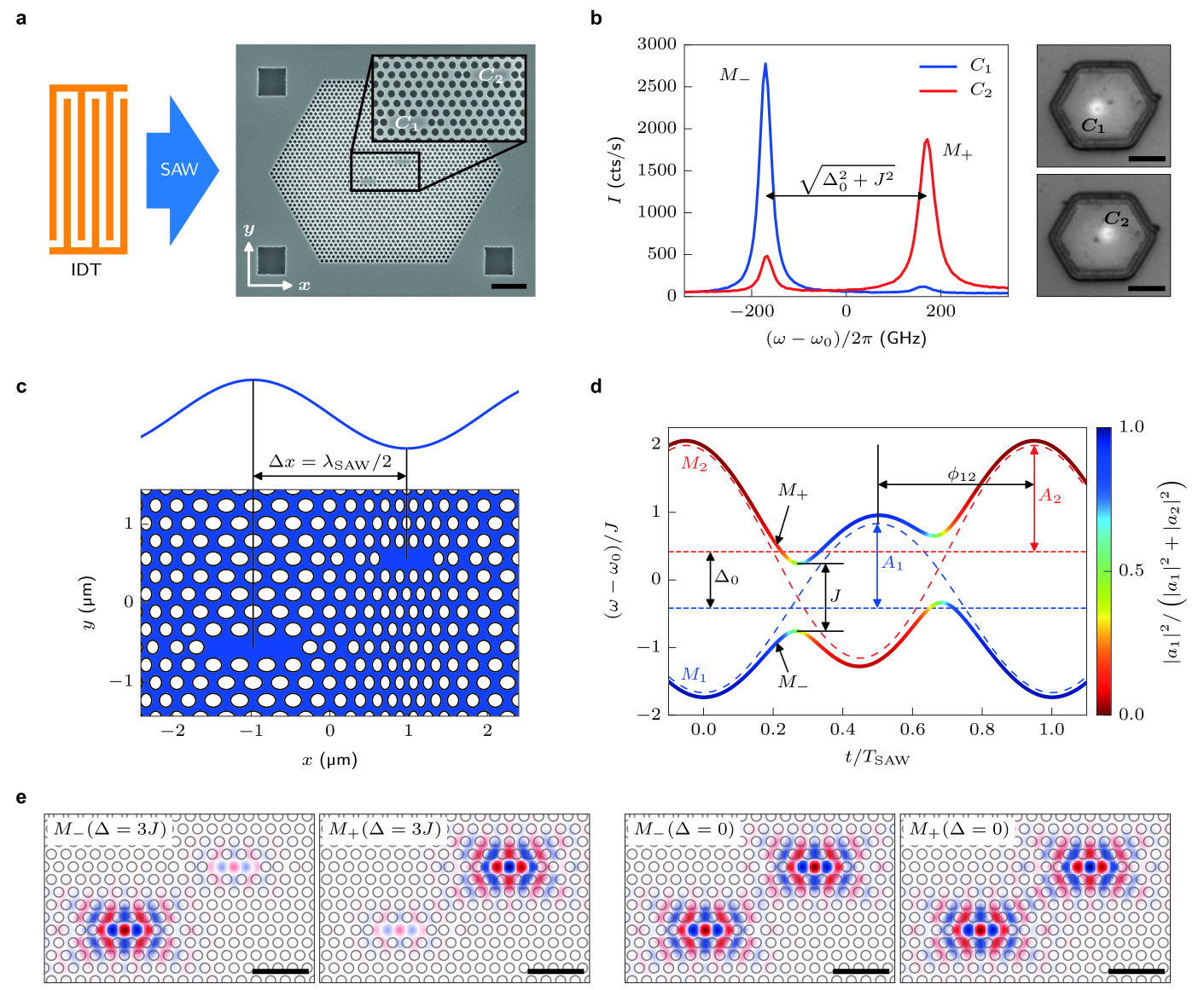
The on-chip photonic molecule (PM) studied here consists of two L3-type missing hole cavities, labeled and , defined in a two-dimensional photonic crystal membrane. Its static coupling strength is known to depend exponentially on the separation between the two cavities Chalcraft_2011 . In our sample the cavities are offset symmetrically by lattice constants along each primitive direction of the photonic crystal (PC) lattice (see Supplementary information), as can be seen in the scanning electron micrograph in Fig. 1 (a). The finite coupling strength leads to the formation of two normal modes; a bonding mode and an antibonding mode . Note that the mode indices in refer to the respective normal mode frequencies and, thus, are opposite to the spatial symmetry of the mode. In the most general case, the two cavities and exhibit resonance frequencies and , split by a finite detuning . Thus, the normal mode frequencies can be expressed by
| (1) |
with being the centre frequency. In Fig. 1 (b) we present two emission spectra of embedded quantum dots (see methods) recorded for spatially exciting either (blue) or (red) of a typical PM, denoted as PM1. For PM1, each cavity exhibits a distinct single mode, split by , with being the static detuning. Therefore, these as-fabricated and nominally identical cavities are efficiently decoupled due to inevitable imperfections during nanofabrication. To overcome this fundamental limitation and achieve dynamic control of the individual cavity resonances we employ an optomechanical approach using radio frequency (rf) surface acoustic waves (SAWs) Lima_2005 ; Fuhrmann_2011 . As indicated in the schematic illustration of Fig. 1 (a), these quasi-monochromatic acoustic phonons are generated by an interdigital transducer (IDT) (see methods), and propagate along the -axis of the PM and dynamically deform the individual cavities. The amplitude of this mechanism, , exceeds both the static detuning, , and the coupling strength, , which enables us to dynamically tune the PM completely in and out of resonance. For our chosen geometric arrangement, the cavities are separated by a distance along the SAW propagation direction, the modulations of and are phase shifted by , with and being the SAW angular frequency and speed of sound, respectively. We deliberately set the acoustic wavelength, , such that it is commensurate with the spatial separation of the two cavity centers . As illustrated in the schematic in Fig. 1 (c), for the selected phase, the maximum (minimum) of the SAW expands (compresses ), which in turn gives rise to a red (blue) shift of their respective resonances Fuhrmann_2011 . The propagation of the sound wave along the -axis of the PM leads to a time-dependent detuning of the two cavities
| (2) |
The amplitude of this modulation, , depends on the amplitudes of the modulations of the individual cavities, and , and is maximum for . For , the detuning passes through zero, which results according to equation (1) in an avoided crossing of the normal modes. In Fig. 1 (d), the resulting temporal evolutions of the normalized mode frequencies obtained using equations (1) and (2) are evaluated over one acoustic cycle of for a typical set of experimentally achievable parameters (, , and ). The dashed lines show the time-evolution of the non-interacting modes (blue) and (red). In strong contrast, the normal modes and start with initially -like (blue) and -like (red) single-cavity character and develop to fully mixed symmetric (bonding) and antisymmetric (antibonding) character (green) at resonance. At this point, the coupling strength of the PM can be deduced directly from the splitting of the avoided crossing. After traversing through the avoided crossing, the initial character of the modes is exchanged, with and possessing -like (blue) and -like character, respectively. Over the duration of one full acoustic cycle the two modes are brought into resonance at two distinct times, giving rise to two avoided crossings, restoring the initial configuration. We performed full finite difference time-domain (FDTD) simulations to confirm and in particular quantify the dynamic coupling. We evaluate the calculated profiles of the electric field component in the plane of the photonic crystal membrane and perpendicular to the SAW propagation in Fig. 1 (e). In the two left panels, the detuning is set to three times the coupling strength and, thus, the two modes remain well localized in one of the two cavities. For the resonance case, , shown in the two right panels of Fig. 1 (e), the exhibit the characteristic symmetric and antisymmetric superpositions for the and modes, respectively. For our sample geometry the FDTD simulations predict . This value is set by the chosen separation, i.e. barrier thickness, between the two cavities.
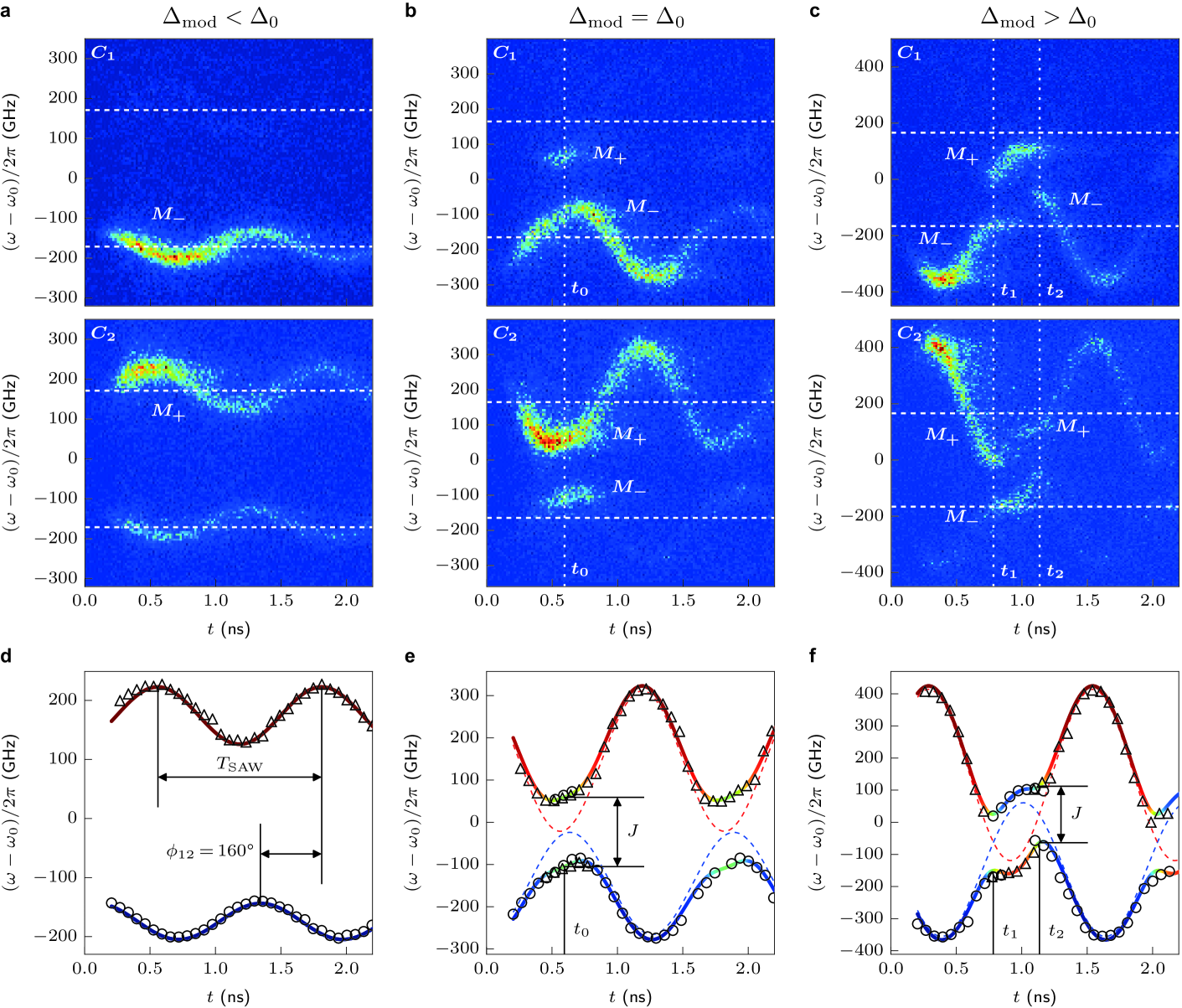
To experimentally verify the dynamic control of a PM by a SAW we performed stroboscopic spectroscopy which ensures optical excitation at a well-defined time during the acoustic cycle. The emission of the PM was analysed in the time-domain and as a function of relative emission frequency . We measured time dependent emission spectra of the two cavities of PM1 for three characteristic modulation amplitudes. For a weak modulation, , shown in Fig. 2 (a), and show the expected phase-shifted sinusoidal spectral modulations centred (dashed horizontal lines) at their unperturbed resonances which decay with a characteristic time constant of . As the modulation is increased to (Fig. 2 (b)) the two single cavity modes are brought into resonance at one distinct time during the acoustic cycle. At this time, coherent coupling leads to the formation of bonding and antibonding normal modes. This directly manifests itself in the experimental data due to the emergence of new emission features stemming from the spatial delocalization of the bonding and antibonding modes. For the initially lower frequency cavity , a new signal appears at the frequency of the normal mode , which was initially confined within the other cavity . The initially higher frequency cavity exhibits precisely the opposite behaviour, with the normal mode appearing at time . The normal modes are split by the coupling strength , very close to the value expected from our FDTD simulations. For further increased detuning , the two modes are brought into resonance at two distinct times, and , during the acoustic cycle. After the first resonance at , coupling is suppressed, , both modes are effectively decoupled and their single cavity characters are exchanged compared to the initial configuration. The lower frequency mode , which is initially -like, is switched to -like character after , and vice versa. At the second resonance at , the system is reverted to its original configuration at the beginning of the acoustic cycle. This sequence of two time-offset coupling events gives rise to the experimentally observed anticorrelated time-evolutions of the emission of and . We extracted the time-dependent emission frequencies detected from the two cavities of PM1 and plotted them ( circles, triangles) for the three modulation amplitudes in Fig. 2 (d-f). All experimental data are well reproduced by the simple coupled mode model given by equations (1) and (2). From the set of measurements with varying tuning amplitude we obtain mean values for the free parameters of the model, , and . Moreover, we note that the observed phase shift unambiguously confirms efficient coupling of the SAW into the sub- membrane. Its small deviation from the ideal value of arises from the finite difference in the phase velocity of the acoustic wave within the membrane and the region of the transducer. The results from this model are plotted as lines and the character of the mode is color coded. Clearly, our experimental data are in excellent agreement with the normal mode model for all three modulation amplitudes. Both the time-dependent spectral modulation as well as the switching of the character of the modes are nicely reproduced.
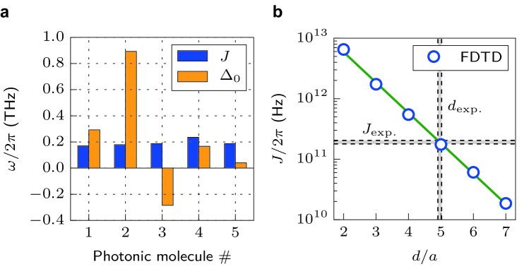
Such behaviour was experimentally confirmed for five different, nominally identical PMs for which we evaluated the mean of their respective key parameters.
The experimentally observed static detuning and coupling strength are summarized in Fig. 3 (a).
While the coupling strength, , (blue) does not vary from PM to PM, the values of the static detuning, , shows a pronounced scatter ranging between and .
These observations are in fact expected.
exponentially depends on the symmetric inter-cavity offset, , and is thus robust and insensitive to small deviations from the ideal geometry due to fabrication imperfections.
In strong contrast, the absolute resonance frequencies of the two cavities forming the PM are highly sensitive to these inherent and inevitable deviations from the nominal geometry.
The resulting fluctuations of the cavity resonances reflect themselves in the observed pronounced variation of .
Indeed, we observe pronounced coupling effects only for one single as-fabricated PM, labeled PM5.
The corresponding experimental data is presented in the Supplementary information.
The exponential dependence of as a function of is nicely confirmed by a best fit (line) to values calculated by FDTD (symbols) presented in Fig. 3 (b).
The experimentally observed distribution of and the inter-cavity separation derived from and the FDTD simulation are indicated by the shaded horizontal and vertical bars.
Clearly, the measured and its derived matching perfectly the calculated value of and the nominally set .
These narrow distributions centred around the calculated and nominal values are expected since is large compared to typical imperfections in the nanofabrication.
In summary, we demonstrated dynamic optomechanical control of coherent interactions in a prototypical coupled nanophotonic system. When combined with optical non-linearities our tunable PM paves the way to dynamically controlled high-fidelity entanglement generation Liew_2010 and distribution on a chip Cirac_1997 ; Vasco_2014 . For larger switching rates as required for Landau-Zener-transition based gates Blattmann_2014 , the underlying optomechanical coupling could be enhanced further by direct SAW excitation of localized vibronic modes of PCM nanocavities Gavartin_2011 or shaped SAW waveforms Schuelein_2015 . Finally we note, that our approach could be directly scaled up to large arrays of coupled cavities Notomi_2008 ; Liew_2013 or employed in superconducting two-level systems, which have recently been strongly coupled to single SAW quanta Gustafsson_2014 .
Methods
Sample structure.
We start by fabricating the photonic crystal membranes from a semiconductor heterostructure grown by molecular beam epitaxy. This heterostructure consists of a 170 nm GaAs layer with self-assembled InGaAs quantum dots (QDs) at its centre, on top of a 725 nm thick sacrificial layer. The PM structure is defined by electron beam lithography and transferred into the heterostructure by ICP-RIE etching. In a wet chemical etching step using hydrofluoric acid we removed the sacrificial layer to release a fully suspended membrane. The PMs are deliberately designed to be off-resonant with the QD emission to achieve a sufficiently long decay time of the cavity emission. Thus, we can observe spectral modulations over more than one acoustic cycle in the time domain, which would be impeded by Purcell-enhanced resonant QD exciton recombinations Fuhrmann_2011 . IDTs were defined using electron beam lithography and metallized with 5 nm Ti and 50 nm Al in a lift-off process. The finger period is , resulting in a resonance frequency of 800 MHz at 5 K.
Optical spectroscopy.
For stroboscopic photoluminescence spectroscopy of the PM, off-resonant QDs are excited by an externally triggered diode laser emitting 90 ps pulses at a wavelength of 850 nm which is focused to a spot by a NIR microscope objective. The emission is dispersed by a 0.75 m imaging grating monochromator. A liquid -cooled Silicon charge coupled device and a fast ( rise time) Si-single photon avalanche detector (SPAD) are used for time-integrated multi-channel or time-resolved single channel detection, respectively. The sample is cooled to in a Helium-flow cryostat with custom built integrated rf connections.
Coupled mode model.
We treat the PM as a model system of two coupled cavities. The single cavity modes have the complex amplitudes and the frequencies . In the presence of finite coupling and the absence of dissipation, the time evolution is given by
with a real coupling constant . The resulting normal modes have the frequencies [Equation (1)] with centre frequency and detuning . We note that since the low frequency mode and the high frequency mode correspond to symmetric and antisymmetric superpositions of the uncoupled, single cavity modes.
References
- (1) Notomi, M. Manipulating light with strongly modulated photonic crystals. Rep. Prog. Phys. 73, 096501 (2010).
- (2) O’Brien, J. L., Furusawa, A. & Vuckovic, J. Photonic quantum technologies. Nature Photon. 3, 687–695 (2009).
- (3) Faraon, A., Majumdar, A., Englund, D., Kim, E., Bajcsy, M. & Vuckovic J. Integrated quantum optical networks based on quantum dots and photonic crystals. New. J. Phys. 13, 055025 (2011).
- (4) Volz, T., Reinhard, A., Winger, M., Badolato, A., Hennessy, K. J.,Hu E. L. & Imamoğlu, A. Ultrafast all-optical switching by single photons. Nature Photon. 6, 605–609 (2012).
- (5) Hartmann, M. J., Brandao, F. & Plenio, M. B. Strongly interacting polaritons in coupled arrays of cavities. Nature Phys. 2, 849–855 (2006).
- (6) Yang, X., Yu, M., Kwong, D.-L. & Wong, C. W. All-Optical Analog to Electromagnetically Induced Transparency in Multiple Coupled Photonic Crystal Cavities. Phys. Rev. Lett. 102, 173902 (2009).
- (7) Grillet, C., Monat, C.,Smith, C. L., Lee, M. W., Tomljenovic-Hanic, S., Karnutsch C. & Eggleton, B. J. Reconfigurable photonic crystal circuits. Laser & Photon. Rev. 4, 192–204 (2010).
- (8) Shevchenko, S. N., Ashhab, S. & Nori, F. Landau-Zener-Stückelberg interferometry. Phys. Rep. 492, 1–30 (2010)
- (9) Vlasov, Y. A., O’Boyle, M., Hamann, H. F. & McNab, S. J. Active control of slow light on a chip with photonic crystal waveguides. Nature 438, 65–69 (2005).
- (10) Tanabe, T. Notomi, M., Kuramochi, E., Shinya, A. & Taniyama, H. Trapping and delaying photons for one nanosecond in an ultrasmall high-Q photonic-crystal nanocavity. Nature Photon. 1, 49-52 (2007).
- (11) Laucht, A.,Hofbauer, F., Hauke, N., Angele, J., Stobbe, S., Kaniber, M., Böhm, G., Lodahl, P., Amann, M. C. & Finley, J. J. Electrical control of spontaneous emission and strong coupling for a single quantum dot. New. J. Phys. 11, 023034 (2009).
- (12) Jin, C.-Y., Johne, R., Swinkels, M. Y., Hoang, T. B., Midolo, L., van Veldhoven, P. J. & Fiore A. Ultrafast non-local control of spontaneous emission. Nature Nanotech. 9, 886–890 (2014).
- (13) Bayer, M., Gutbrod, T., Reithmaier, J. P., Forchel, A., Reinecke, T. L., Knipp, P. A., Dremin, A. A. & Kulakovskii, V. P. Optical modes in photonic molecules. Phys. Rev. Lett. 81, 2582–2585 (1998).
- (14) Chalcraft, A. R. A., Lam, S., Jones, B. D., Szymanski, D., Oulton, R., Thijssen, A. C. T., Skolnick, M. S., Whittaker, D. M., Krauss, T. F. & Fox, A. M. Mode structure of coupled L3 photonic crystal cavities. Opt. Express 19 5670-5675 (2011).
- (15) Fuhrmann, D. A., Thon, S. M., Kim, H., Bouwmeester, D., Petroff, P. M., Wixforth, A. & Krenner, H. J. Dynamic modulation of photonic crystal nanocavities using gigahertz acoustic phonons. Nature Photon. 5, 605-–609 (2011).
- (16) Li, H. & Li, M. Optomechanical photon shuttling between photonic cavities. Nature Nanotech. 9, 913–-919 (2014).
- (17) Blattmann, R., Krenner, H. J., Kohler, S. & Hänggi, P. Entanglement creation in a quantum-dot–nanocavity system by Fourier-synthesized acoustic pulses. Phys. Rev. A 89, 012327 (2014).
- (18) Schülein, F. J. R., Zallo, E., Atkinson P., Schmidt, O. G., Trotta, R., Rastelli, A., Wixforth, A. & Krenner, H. J. Fourier-synthesis and acoustic timbre tuning of radio frequency nanomechanical pulses. Nature Nanotech. accepted for publication, preprint arXiv:1412.1071 (2014).
- (19) Sato, Y., Tanaka, Y., Upham, J., Takahashi, Y., Asano T. & Noda S. Strong coupling between distant photonic nanocavities and its dynamic control. Nature Photon. 6, 56–-61 (2012).
- (20) Bose, R., Cai, T.,Choudhury, K. R., Solomon, G. S. & Waks E. All-optical coherent control of vacuum Rabi oscillations. Nature Photon. 8, 858-–864 (2014).
- (21) de Lima, M. M. & Santos, P. V. Modulation of photonic structures by surface acoustic waves, Rep. Prog. Phys. 68, 1639–1701 (2005).
- (22) Cai, T., Bose, R., Solomon, G. S. & Waks, E. Controlled coupling of photonic crystal cavities using photochromic tuning. Appl. Phys. Lett. 102, 141118 (2013).
- (23) Gavartin, E., Braive, R., Sagnes, I., Arcizet, O., Beveratos, A., Kippenberg, T. J. & Robert-Philip I. Optomechanical Coupling in a Two-Dimensional Photonic Crystal Defect Cavity. Phys. Rev. Lett. 106, 203902 (2011).
- (24) Liew, T. C. H. & Savona V. Single Photons from Coupled Quantum Modes. Phys. Rev. Lett. 104, 183601 (2010).
- (25) Cirac, J. I., Zoller, P., Kimble, H. J. & Mabuchi H. Quantum State Transfer and Entanglement Distribution among Distant Nodes in a Quantum Network. Phys. Rev. Lett. 78, 3221–3224 (1997).
- (26) Vasco, J. P., Guimarães, P. S. S. & Gerace D. Long-distance radiative coupling between quantum dots in photonic crystal dimers. Phys. Rev. B 90, 155436 (2014).
- (27) Notomi, M., Kuramochi, E. & Tanabe, T. Large-scale arrays of ultrahigh-Q coupled nanocavities. Nature Photon. 2, 741–747 (2008).
- (28) Liew T. H. C. & Savona V. Multimode entanglement in coupled cavity arrays. New J. Phys. 15, 025015 (2013).
- (29) Gustafsson, M. V., Aref, T., Kockum, A. F., Ekström, M. K., Johansson, G. & Delsing, P. Propagating phonons coupled to a superconducting qubit. Science 346, 207–211 (2014).
Acknowledgements
This work was supported by the Deutsche Forschungsgemeinschaft (DFG) via the Emmy-Noether-Programme (KR 3790/2-1), Sonderforschungsbereich 631 and the Cluster of Excellence Nanosystems Initiative Munich (NIM). K. M. acknowledges support by the Alexander-von-Humboldt-Foundation.
Author contributions
H.J.K. and S.K. designed study. S.K. built the experimental setup and performed the experiments. S.K., T.R. and S.L. designed, fabricated and characterised the devices, and performed 3D-FDTD simulations. K.M. fabricated and characterized the MBE material. S.K. and H.J.K. performed the data analysis and modelling. All authors discussed the results. S.K. and H.J.K. wrote the manuscript with contributions from all other authors. H.J.K., M.K., J.J.F. and A.W. inspired and supervised the project.