Inclination-Induced Polarization of Scattered Millimeter Radiation from Protoplanetary Disks: The Case of HL Tau
Abstract
Spatially resolved polarized millimeter/submillimeter emission has been observed in the disk of HL Tau and two other young stellar objects. It is usually interpreted as coming from magnetically aligned grains, but can also be produced by dust scattering, as demonstrated explicitly by Kataoka et al. for face-on disks. We extend their work by including the polarization induced by disk inclination with respect to the line of sight. Using a physically motivated, semi-analytic model, we show that the polarization fraction of the scattered light increases with the inclination angle , reaching for edge-on disks. The inclination-induced polarization can easily dominate that intrinsic to the disk in the face-on view. It provides a natural explanation for the two main features of the polarization pattern observed in the tilted disk of HL Tau (): the polarized intensity concentrating in a region elongated more or less along the major axis, and polarization in this region roughly parallel to the minor axis. This broad agreement provides support to dust scattering as a viable mechanism for producing, at least in part, polarized millimeter radiation. In order to produce polarization at the observed level (), the scattering grains must have grown to a maximum size of tens of microns. However, such grains may be too small to produce the opacity spectral index of observed in HL Tau and other sources; another population of larger, millimeter/centimeter-sized, grains may be needed to explain the bulk of the unpolarized continuum emission.
keywords:
dust - polarization - protoplanetary disks1 Introduction
Polarized millimeter/sub-millimeter emission has been observed in the disks around 3 young stellar objects: IRAS 16293-2422B (Rao et al., 2014), HL Tau (Stephens et al., 2014) and L1527 (Segura-Cox et al., 2015). It is usually interpreted as coming from magnetically aligned dust grains (e.g., Cho & Lazarian 2007). This interpretation appears consistent with the data on IRAS 16293-2422B and L1527, where the observed polarization patterns are broadly similar to those expected from grains aligned by a predominantly toroidal magnetic field (Rao et al. 2014; Segura-Cox et al. 2015; see § 5 for more discussion). In contrast, the polarization vectors in the disk of HL Tau (which is inclined with respect to the line of sight by , ALMA Partnership: Brogan et al. 2015; Kwon et al. 2011) are all roughly parallel to the minor axis (see Fig.1), which is not compatible with the pattern expected of grains aligned by a toroidal disk field, although more complicated field configurations cannot be ruled out (Stephens et al., 2014). Another drawback of the toroidal field-aligned grain model is that it predicts a lower polarization fraction along the major axis than along the minor axis (see Cho & Lazarian, 2007, Fig. 10), which is the opposite of what is observed (Fig. 1). A much better fit is provided by a uni-directional magnetic field approximately (within ) along the disk major axis. However, such a field configuration would be difficult to maintain against the disk differential rotation. Furthermore, there is growing evidence for grain growth in protoplanetary disks, up to millimeter or even centimeter sizes (e.g., Pérez et al. 2012; Alecian 2013; Testi et al. 2014). It is unclear whether such large grains would be aligned with respect to the magnetic field through the currently favored mechanism of radiative torque because their magnetic moments may not be large enough to provide the fast precession needed (Lazarian, 2007) and their slow internal relaxation makes the alignment less efficient (Hoang & Lazarian, 2009). These difficulties provide a motivation to investigate other potential mechanisms for producing, at least in part, the polarized mm emission from the HL Tau disk.
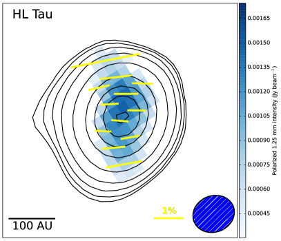
One possibility, first investigated in detail by Kataoka et al. (2015a), is that the polarized millimeter disk emission comes from scattering of large dust grains. Kataoka et al. stressed the need for anisotropic radiation field for this mechanism to work efficiently. As examples of this requirement, they considered radiation from structured disks with either an axisymmetric ring or a non-axisymmetric lobe, both viewed face-on. Here, we extend Kataoka et al.’s work to show that significant polarization is produced even in a smooth disk, as long as the disk axis is tilted away from the line of sight by a large enough angle. The physical reason can be understood most easily in the limits of optically and geometrically thin dust emission and Rayleigh scattering, where the degree of polarization is peaked near a scattering angle of . In these limits, the radiation field to be scattered by dust grains becomes essentially two dimensional, concentrated in the disk plane. In such a case, only the radiation propagating along the disk major axis would be scattered by to reach the observer and be maximally polarized, with a polarization direction along the minor axis in the plane of the sky. This simple geometric effect provides a natural explanation for the two main features of the polarization pattern observed in the HL Tau disk (see Fig. 1): (1) polarized emission concentrating in an elongated region more or less along the major axis, and (2) polarization vectors in this region roughly parallel to the minor axis. These are the features that are difficult to explain in the current models of polarization from magnetically aligned grains111Grains aligned by a toroidal magnetic field can explain the orientations of the polarization vectors near the center, but not at larger distances (see the left panel of Fig. 2 of Stephens et al. 2014).. They provide a strong motivation to explore in more detail the polarization pattern produced by dust scattering. It is a first step toward disentangling the contributions of dust scattering and grain alignment to the disk polarization, which is needed in order to take full advantage of the high resolution ALMA and JVLA polarization observations that will become available soon for probing the grain growth and/or magnetic field in protoplanetary disks.
In the remainder of the paper, we will put the above qualitative picture on a more quantitative ground by computing the scattered radiation from an inclined disk (such as the HL Tau disk) semi-analytically using the so-called “thin-disk” approximation that brings out the essential physics transparently (§ 2); a more complete treatment of the radiative transfer problem will be postponed to a future investigation. The effects of disk inclination on the polarization pattern will be emphasized. The scattered radiation is compared with the direct dust emission in § 3, where the fractional polarization of the total intensity is computed. In § 4, we comment on the implications of the polarization fraction observed in HL Tau on the grain size distribution. We discuss the possibility of dust scattering-induced polarization for other sources and future model refinements in § 5 and conclude in § 6.
2 Polarized Radiation from Dust Scattering
In this section, we develop a semi-analytic model for polarization from dust scattering under the simplifying assumptions that the dust emission is optically thin and that the dust disk is geometrically thin, with a local scale height much less than the radius. The latter would be a particularly good approximation if the relatively large grains responsible for the emission and scattering of millimeter radiation are settled toward the disk mid-plane. To isolate the polarization due to dust scattering from that caused by grain alignment, we further assume that the grains are not aligned, so that the radiation directly emitted by dust is unpolarized. Under these assumptions, the incoming radiation field seen by the scattering dust grains at a given point inside the disk can be decomposed into two components: a local, roughly isotropic, component emitted by the (non-aligned) grains in a region of size comparable to the (dust) scale height surrounding the point, and an anisotropic component coming from the grains in the rest of the disk beyond the local region. The former does not lead to significant polarization after scattering because scattering of isotropic radiation by non-aligned grains does not have any preferred direction. It is the latter that is mainly responsible for the polarized radiation after scattering. The computation of this component will be drastically simplified by the thin-disk approximation, as we show below.
2.1 Formulation of the Problem
To facilitate the computation of the scattered light from dust grains at a location inside a disk with axis inclined by an angle with respect to the line of sight, we define two coordinate systems, both centered on the scatterer’s location . The first is fixed in the observer’s frame, with horizontal - and vertical - axes in the plane of the sky, and -axis pointing toward the observer. The second is fixed on the disk, with the -axis coinciding with the -axis, and the - and -axis rotating around the -axis counter-clockwise (viewed along the minus -axis) from the - and -axis, respectively, by the inclination angle . We align the major axis of the disk in the plane of the sky along the - (and -) axis (see Fig. 2 below for an illustration), and the disk normal direction along the -axis.
Since the scattered radiation is linearly polarized, we will compute the three Stokes parameters , and defined in the observer’s frame separately, starting with the intensity (we drop the subscript for and since, in our model, they are assumed to be produced only by the scattered radiation, without any contribution from the direct radiation, unlike the total intensity ). In the optically thin limit, the intensity of the scattered radiation along the line of sight is given by an integration of the source function of the scattered radiation, , along the -axis. The source function at any location inside the disk is given by
| (1) |
where is the intensity of the unpolarized incoming radiation seen by the scattering dust grains at the location along the direction of polar angle (measured from the -axis or the disk normal direction) and azimuthal angle (measured counter-clockwise from the -axis on the disk), is the solid angle -integrated (total) scattering cross section, and is the differential cross section for scattering the radiation into the line of sight (i.e., along the -axis).
The intensity is given by an integration of the source function for thermal dust emission, the Planck function , over the optical depth (where is the thermal dust absorption opacity and the mass density at a source location ) along a line in the direction up to the scatterer at (the quantity is the distance between and ):
| (2) |
where we have assumed that the photon energy is substantially less than so that the Rayleigh-Jeans law is applicable; we have checked that, for the HL Tau model to be discussed below in § 2.3, the results will not change significantly if the Planck function is used instead.
Substituting the above expression for into Eq.(1) and reorder the integrals, we can rewrite the source function for the scattered radiation into:
| (3) |
where
| (4) |
and
| (5) |
The two quantities, and , denote the contributions to the unpolarized incoming radiation to be scattered at the location from two conceptually distinct regions respectively. For a geometrically thin dust disk, the unpolarized radiation coming from a region within a distance on the order of the local (dust) scale height is expected to be more or less isotropic. This near-field contribution, denoted by , produces little polarized radiation after scattering; it will be discussed in the next section, together with the unpolarized direct dust emission. In contrast, the thermal dust emission coming from well outside this local region (i.e., ) is mostly confined close to the disk plane. This far-field contribution, denoted by , is highly anisotropic, with the bulk of the radiation beamed into a narrow range of polar angle near along any azimuthal direction . Specifically, the vertical column of disk material passing through the source location at a distance from the scatterer contributes radiation only within a range of polar angle , where is the (dust) scale height at . Replacing the integral over angle in the expression for (eq. (5)) by this rough estimate and making use of , we have approximately
| (6) |
where we have assumed a spatially constant absorption opacity for simplicity. The auxiliary quantity is a line integral along the direction of constant in the disk plane defined as
| (7) |
where is the column density at the source location .
One can determine the distance between the source location and the center of the disk through
| (8) |
where and are the radius and azimuthal angle of the scatterer in an coordinate system that centers on the star (rather than the scatterer at ). For the axisymmetric disk that we will consider below, the radius uniquely determines the column density and temperature that appear in eq.(7).
Once the integral is computed, the only term that is left to determine in eq.(6) is the differential cross section for scattering . For illustrative purposes, we will consider the dust scattering under the Rayleigh approximation, which is valid when the grain sizes are smaller than the wavelength divided by (see, e.g., Fig. 10 of Canovas et al. 2013 and Fig. 6 below); we will check in § 4.1 that this condition is satisfied for the HL Tau model to be discussed in the next section. In this limit, the differential cross section is given by
| (9) |
where is the scattering angle between the incoming radiation along the direction and the outgoing radiation along the line of sight (i.e., the -axis), given by
| (10) |
After scattering, a fraction of the initially unpolarized incoming radiation becomes polarized. The polarization fraction is
| (11) |
which peaks at .
The polarization direction is perpendicular to the scattering plane formed by the incoming direction and the -axis. It lies in the - plane of the sky, at an angle measured counter-clockwise from the -axis, with the angle given by
| (12) |
This linearly polarized radiation is the source of the observed polarized radiation in the plane of the sky, through the source functions for the Stokes parameter and :
| (13) |
and
| (14) |
For the optically thin radiation that we are considering, and along the line of sight passing through any location in the disk is simply given by their respective source functions, multiplied by the optical depth for scattering (where is the scattering opacity) through the disk: and .
2.2 Inclination-Induced Polarization
As a simple illustration of polarization from scattered light induced by disk inclination, we consider the limiting case where the incoming radiation field seen by the scatterer at the location is confined to an infinitely thin disk plane (so that the near-field contribution to the scattering source function, , can be ignored compared to the far-field contribution ) and is isotropic in the azimuthal () direction (but highly anisotropic in polar angle ). In this case, the integral defined in eq. (7) is independent of and can be moved outside the integral over in the source functions for the total scattered intensity (eq. (6)), Q (eq. (13)) and U (eq. (14)), so that
| (15) |
where is a constant independent of the angles and , and
| (16) |
| (17) |
The fact that is zero and is positive (for ) means that the inclination-induced polarization is always along the -axis (or the minor axis of the disk) in the plane of the sky for Rayleigh scattering (see Fig. 2 for the - coordinates, and eq. (23) below for the relation between the Stokes parameters and , and polarization angle ). This is expected physically because, in a tilted disk, the light coming from different directions in the disk plane will be scattered by different angles toward the observer. In particular, the light coming from a direction along the major axis will always be scattered by . In the Rayleigh limit, this part of the light will be fully polarized along the minor axis of the disk. In contrast, the light coming from a direction along the minor axis will be scattered by either or . This part of the light will be partially polarized along the major axis, with a polarization fraction of . The difference in the fraction of polarization leads to more scattered light polarized along the minor axis than along the major axis, despite the fact that the scattering cross section is less for the former than the latter (see eq. (9)). This generic tendency for the inclination-induced polarization to align with the minor axis provides a natural explanation for the polarization directions observed in HL Tau (see Fig. 1).
It is easy to determine the fraction of the total scattered light that is polarized along the minor axis:
| (18) |
This same expression can be obtained if one considers only the radiation coming from directions along the major and minor axes. Note that the maximum degree of polarization reaches when the disk is viewed edge-on (). For the inclination angle , , and to be considered in the next subsection, the fractional polarization is , , , and , respectively. The analytically obtained polarization fraction in this simple limiting case will be used to interpret the results obtained numerically in more general cases.
2.3 Intrinsic Polarization from Azimuthally Anisotropic Radiation: an Example
As emphasized by Kataoka et al. (2015a), the radiation field in the disk plane is not isotropic in general, and the anisotropy in the azimuthal () direction leads to polarized scattered light even in the face-on case. In a tilted disk, the observed polarization pattern is expected to be shaped by the interplay between those produced by anisotropy in -direction and disk inclination (which relies on strong anisotropy in direction). To illustrate this interplay, we adopt Kwon et al. (2011) model of the HL Tau disk, where the distributions of temperature and column density as a function of the cylindrical radius are parametrized as
| (19) |
| (20) |
where is a characteristic disk radius beyond which the column density drops off exponentially, and is an exponent that, together with the exponent , controls the column density distribution; it is not to be confused with the polarization fraction. The temperature profile yields a thermal scale height for the gas
| (21) |
Although higher resolution ALMA observations have revealed substructures (rings) on the disk (ALMA Partnership: Brogan et al., 2015), the above is still the best model at the CARMA resolution that was used to detect the polarization in HL Tau. Adopting , Kwon et al. found a set of parameters that best fit their CARMA observations at 1.3 and 2.7 mm: AU, , and a scale height for gas at of AU (see also Kwon et al. 2015). Since the relatively large grains responsible for the scattered radiation may settle toward the midplane, the scaling factor in eq.(21) may need to be reduced by some (potentially large) factor (Kwon et al., 2011). We have experimented with reduction factors of , , and , and found very similar results. In what follows, we will focus on the case where the scale height is the same for the dust and gas.
With the disk structure specified, we can now compute the Stokes parameters , and from their source functions given by eqs. (13), (14) and (6). In this section, we consider the contribution to the total observed intensity from the far-field scattering source function only, in order to facilitate comparison with the analytic results obtained in the preceding subsection; the contributions from and direct dust emission would lower the polarization fraction, and will be considered in the next section. From these three Stokes parameters, we can determine the total intensity of the polarized radiation
| (22) |
the polarization angle (measured counter-clockwise from the -axis in the plane of the sky)
| (23) |
where the function returns the appropriate quadrant of the computed angle based on the signs of and , and the polarization fraction
| (24) |
which can be compared directly with that given analytically in eq. (18).
In Fig.2, we show the polarization vectors and the spatial distribution of the polarized intensity for , , , and . The intensity is measured in units of , where and are the characteristic column density and temperature of the disk, and and the absorption and scattering opacity. In the face-on () case, the fraction of polarization of the scattered light is zero at the center because the light to be scattered there comes isotropically along all azimuthal directions for the prescribed axisymmetric disk. The radiation seen by the scatterer becomes more and more beamed in the radial direction as the radius increases, because of the drop in temperature and column density. As a result, the light is polarized in the azimuthal direction and the polarization degree increases outward. We will refer to the polarization induced by anisotropic radiation in the azimuthal direction in the face-on case as the “intrinsic” polarization. Note that although the polarization fraction can reach a value as high as or more near the outer edge, the total scattered polarized intensity is rather low. As a result, the intrinsic polarization from dust scattering can be easily modified, indeed dominated, by the inclination-induced polarization.
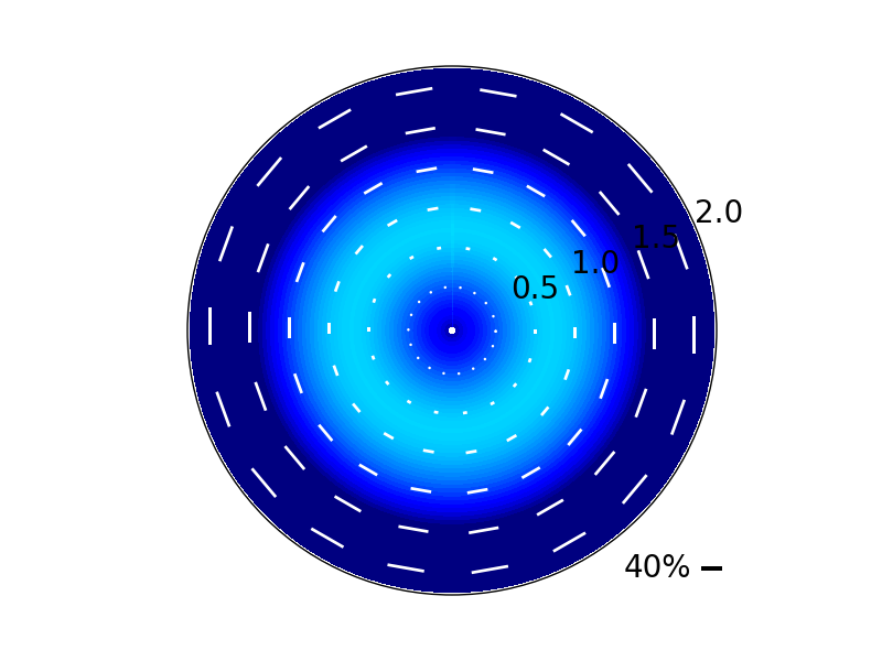
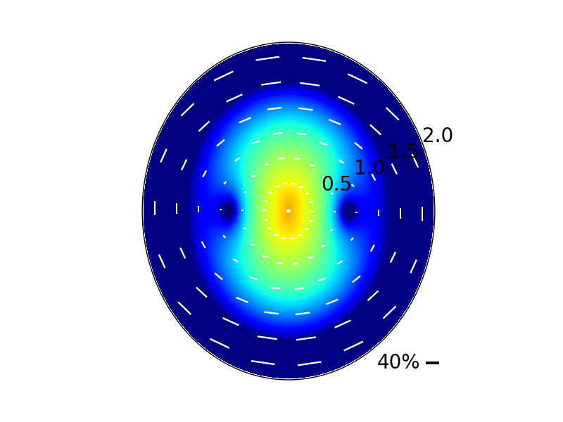
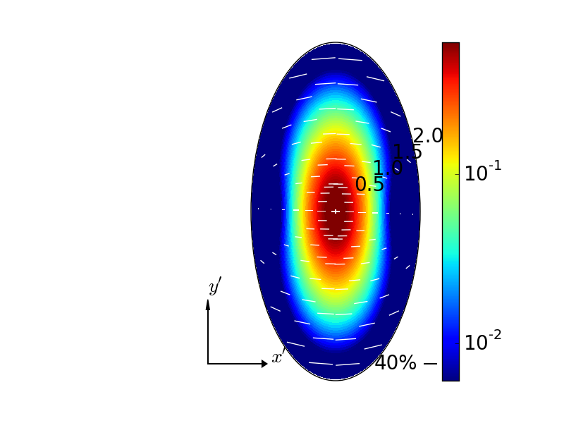
When the disk is tilted away from the line of sight, both the polarized intensity and orientations of the polarization vectors change drastically compared to the face-on case. As Fig. 2 shows, the polarized intensity peaks at a ring in the face-on case, with the inward decrease caused by radiation becoming more isotropic in the azimuthal direction and the outward decrease from the exponential drop-off in column density. In contrast, the polarized intensity in the case peaks in the central region, as a result of the inclination-induced polarization. The polarization vectors in this (central) region (within of the origin) lie more or less along the minor axis, consistent with the analytic results for the inclination-induced polarization derived in the last subsection. Outside the central region, the polarization directions are broadly similar to those in the face-on case, indicating that the intrinsic polarization remains important there. A difference is that the axisymmetric polarization pattern in the face-on case becomes highly non-axisymmetric in this moderately tilted case, with both the polarized intensity and the polarization fraction significantly higher along the major axis than along the minor axis.
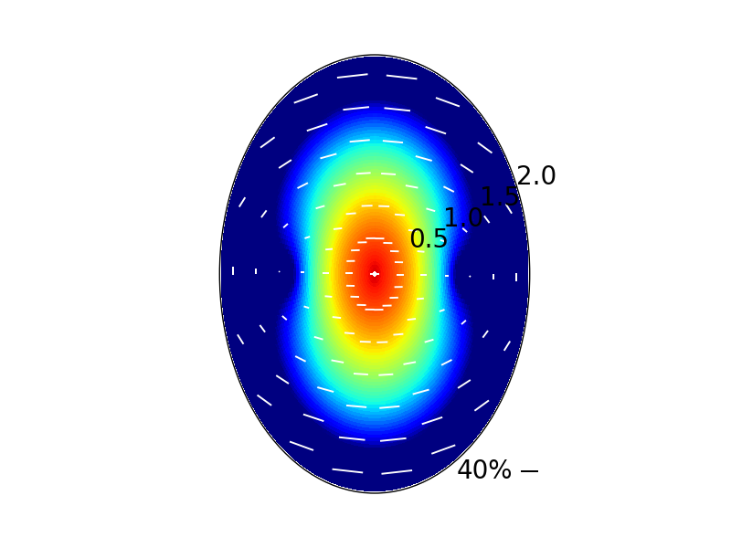
As the disk tilt angle increases further, the polarization pattern becomes more dominated by that induced by inclination. Going from to to , we see a clear trend for increasing polarized intensity in the central region, a larger fraction of the polarization vectors parallel to the minor axis, and more elongation of the polarized intensity along the major axis (see Fig.2). The elongation is a generic feature of the interplay between the intrinsic polarization and inclination-induced polarization. It provides a natural explanation for the distribution of polarized intensity observed in HL Tau222The observed direction of elongation does not lie exactly along the major axis, but is offset by a small angle of (see Stephens et al. 2014 and Fig. 1). This offset is not explained in our model under thin-disk approximation, and may require full 3D models and/or additional physics, such as grain alignment., which has an inclination angle of (ALMA Partnership: Brogan et al., 2015; Kwon et al., 2011).
2.4 Interplay Between Intrinsic and Inclination-Induced Polarization
To understand the interplay between the intrinsic polarization and inclination-induced polarization more quantitatively, we plot in Figure 3 the distribution of a dimensionless quantity
| (25) |
along the major and minor axes for the case. Since along the major and minor axes, this quantity is essentially the polarization fraction defined in eq.(24), except that it retains the sign of the Stokes parameter . A positive (negative) means that the polarization is along the -axis (-axis) in the plane of the sky.
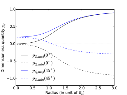
In the face-on case (), the intrinsic polarization fraction increases monotonically from zero to a large value approaching unity as the distance from the origin increases along the major (or -) axis, with the polarization vectors parallel to the -axis in the plane of the sky. The quantity is thus positive, as shown in Fig. 3 (solid black line). Along the minor axis, the fractional polarization is the same, but the polarization direction is along the -axis, with a negative (dashed black line). For comparison, we plot in the same figure the numerically computed distribution of along the major and minor axes as a function of the (de-projected) distance from the origin for the case. Clearly, the inclination has shifted the curves for the intrinsic () along both major and minor axes upward, which is not surprising since inclination tends to produce polarization along the -direction (corresponding to a positive , see eq.16). The amount of upward shift is different at different locations, however. In the central region where the intrinsic polarization fraction is relatively low (within about 0.5 Rc), the shift is by along both the major and minor axes; it is the value expected from the analytic results for an azimuthally isotropic radiation field given in eq. (18). The behavior in the central region where the intrinsic polarization is weak is therefore easy to understand; it is dominated by the inclination-induced polarization.
The behavior outside the central region where the intrinsic polarization fraction is higher is more complicated. It can be reproduced exactly, however, by the formula
| (26) |
along both the major and minor axes. Note that the first term on the right hand side is simply the inclination-induced polarization given by eq. (18), and the second term is the intrinsic polarization fraction (the face-on case) modified by the inclination. This formula can be derived heuristically under the assumption that the radiation seen by the scatterer comes from only two directions: the - and -axes in the disk plane.
In the limit where the intrinsic polarization fraction , we have
| (27) |
In the opposite limit where the intrinsic polarization fraction , we need to consider the major and minor axes separately. Along the major axis where is positive, we have , which yields
| (28) |
Along the minor axis where is negative, we have , so that
| (29) |
which, for shown in Fig. 3, approaches . The difference in the asymptotic behavior of , particularly the polarization fraction , highlights one of the major differences between the polarization patterns along the major and minor axes. It becomes more extreme as the inclination angle approaches .
Another difference is that there exists a point of zero polarization on the minor axis across which changes sign (or the polarization direction changes by ). This null point occurs at a location where
| (30) |
which has a value of for . Indeed, if the inclination angle is known independently, one can in principle deduce the intrinsic value of along the major and minor axes from the value of through
| (31) |
However, it is difficult to infer the value of from observation directly because it is the observed Stokes Q parameter normalized by the scattered intensity from the far-field, , which cannot be measured directly. What can be measured is the total intensity, which we discuss next.
3 Total Intensity and Polarization Fraction
The total intensity of the radiation along the line of sight is the sum of the direct dust emission , the scattered radiation from near-field , and the scattered radiation from far-field . The source function for the near-field contribution at a location inside the disk can be estimated approximately assuming isotropic incoming radiation from within a uniform sphere of radius , the local scale height:
| (32) |
which is multiplied by the scattering optical depth to yield the intensity
| (33) |
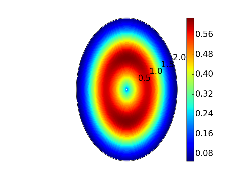
For the HL Tau disk model discussed in § 2.3, the intensity of the scattered radiation from the near-field is weaker than that from the far-field everywhere for , as can be seen from Fig. 4, where the ratio of the two is plotted. The ratio peaks in a ring between and (where is the characteristic radius of the disk), with a maximum value of . Near the peak, the unpolarized scattering intensity reduces the polarization fraction by a factor of , from to . Going outward from the ring, the ratio drops rapidly because the near-field intensity is determined by the local column density, which drops off exponentially with radius, whereas the far-field intensity is determined globally, including contributions from the bright central region that decrease with radius more slowly than exponential. Inside the ring, the ratio decreases with decreasing radius because of a smaller scale height , which decreases the size of the region where the incoming radiation for the near-field source function comes from relative to that for the far-field source function . In any case, the polarization fraction of the scattered radiation remains high, of order or more, after both the near- and far-field contributions are taken into account. It is much higher than observed in HL Tau (of order ), and needs to be further reduced, by the unpolarized direct dust emission333Direct emission can be polarized, due to, for example, grain alignment. Polarized direct emission needs to be included in a more complete model (as discussed in § 5)..
The source function for the direct emission is simply the Planck function . The optical depth for dust absorption along the line of sight passing through a location in the disk is under the thin disk approximation. Together, they yield the intensity for the direct emission
| (34) |
This estimate allows us to evaluate the ratio of the intensities of the scattered and direct emission:
| (35) |
Note that the ratio and the second term inside the square bracket are dimensionless quantities that depend only on the shape of the column density and temperature profiles. The overall scaling is set by the characteristic scattering optical depth . In order to reduce the high polarization fraction of the scattered radiation at 1.3 mm to the observed value of about , we need a rather small value of , so that the scattered radiation is heavily diluted by the unpolarized direct emission.
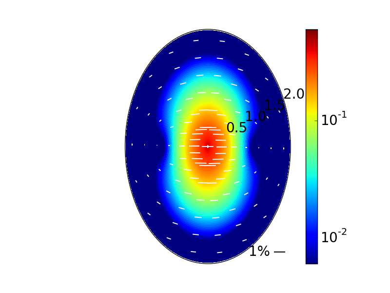
We stress that the inclusion of the unpolarized radiation and changes neither the polarized intensity nor the polarization direction shown in Fig. 2 (the lower-left panel). What is changed is the polarization fraction. In Fig. 5, we plot the distribution of the polarized intensity for the case, as in the lower-left panel of Fig. 2, but with the length of the overlaid polarization vectors scaled by the new polarization fraction (relative to the total intensity). This figure represents our final model for the HL Tau disk. It has three features that are broadly consistent with observations: (1) the region of high polarized intensity is elongated along the major axis, (2) the polarization vectors in this region are nearly parallel to the minor axis, and (3) the polarization fraction in the region is about . Along the ridge of detectable polarized intensity, the observed polarization fraction appears to be somewhat higher toward the edge of the disk (at a distance of AU) than near the center, although it is unclear how significant the trend is in view of the low polarized intensity near the edge. This trend was present in our model when only the scattered radiation was considered (see Fig. 2 and 3), but was washed out by the total intensity in Fig. 5.
The semi-analytic theory that we have developed so far under the assumption of geometrically thin disk, optically thin emission, and only Rayleigh scattering is independent of the detailed properties of dust grains. This independence makes the broad agreement between our model and the main polarization features observed in HL Tau rather robust. In the next section, we will try to put constraints on the grain size distribution in the HL Tau disk, which is much more uncertain.
4 Implications on Grain Size
4.1 Scattering Opacity and the Need for Large Grains
The main free parameter of the final model for the HL Tau disk polarization discussed in § 3 is the characteristic scattering optical depth , which controls the polarization fraction. In order to produce the observed polarization fraction of , a value of is required. This value yields a scattering opacity cm2 g-1 (cross section per unit total, rather than dust, mass) at 1.3 mm (the wavelength of the HL Tau disk polarization observation), using the characteristic column density g cm-2 from the best-fit disk mass of M⊙ of Kwon et al. (2011). This scattering opacity can put constraints on the grain size distribution, although they depend on the dust composition, which is uncertain. As an illustration, we consider the model of dust grains adopted by Kataoka et al. (2015a), which are spheres with a mixture of silicate (8%), water ice (62%) and organics (30%). All fractional abundances are in volume and are taken from Pollack et al. (1994). We assume a canonical gas-to-dust mass ratio of 100, and use the Mie theory to calculate the absorption and scattering opacities (Bohren & Huffman, 1983). The inferred scattering opacity corresponds to a grain radius for grains of a single size. For the MRN-type power-law distribution (Mathis et al., 1977), we obtain a maximum grain size of . The increase of this maximum over the single size case comes from averaging over the grain size. In both cases, the dimensionless parameter , so that the Rayleigh limit used for treating the scattering in the previous sections is self-consistent (see Fig. 6 below). The maximum size inferred for the grains responsible for the scattered dust emission in the HL Tau disk is much larger than that of the grains in the diffuse interstellar medium. This is consistent with other lines of evidence for grain growth in disk environments (e.g., Pérez et al. 2012; Alecian 2013; Testi et al. 2014).
We note that Kataoka et al. (2015b) independently modeled the HL Tau disk polarization using dust scattering through Monte Carlo radiative transfer simulations. They obtained disk polarization patterns that are very similar to ours. They inferred a maximum grain size that ranges from 70 m to 350 m, which is broadly consistent with our value of 72 m.
In summary, to reproduce the polarization fraction observed in the disk of HL Tau through dust scattering, the grains must have grown to tens of microns (the exact value depends on the assumed grain size distribution and composition). However, this picture is complicated by the opacity spectral index inferred for HL Tau, as we discuss next.
4.2 Opacity Spectral Index and the Need for Larger Grains?
Kwon et al. (2011) obtained a best-fit value for the spectral index of the dust opacity for the HL Tau disk based mostly on CARMA observations at 1.3 and 2.7 mm. It is in agreement with the spatially averaged value obtained from ALMA observations from 0.87 to 2.9 mm (ALMA Partnership: Brogan et al., 2015). This value is significantly lower than the typical ISM value of . The difference is usually taken as evidence for grain growth to millimeter size or larger (Testi et al., 2014), although other interpretations are possible. For example, Ricci et al. (2012) showed that a value of or lower can be obtained without mm/cm sized grains if part of the disk is optically thick. Some support for this possibility is provided by the spatially resolved distribution of derived from the ALMA data, which shows indicative of optically thick emission at the central continuum peak and two rings (B1 and B6, ALMA Partnership: Brogan et al. 2015, see their Fig. 3). Another possibility is that the index is sensitive to not only the size but also the shape of the grains. Indeed, Verhoeff et al. (2011) was able to reproduce the spectral energy distribution (SED) of the disk of HD 142527 (with in the millimeter regime) with irregular grains of sizes up to only 2.5 ; the grain shape was treated with the distribution of hollow spheres Min et al. (2005). The grains inferred in our model of dust scattering-induced polarization for the HL Tau disk have a significantly larger maximum size (of order tens of microns). They may still be able to reproduce the observed (averaged) opacity spectral index of if the grains are irregular and/or part of the disk is optically thick. Detailed exploration of this possibility is beyond the scope of the present work.
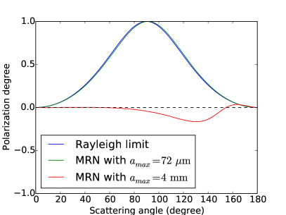
If large, mm/cm sized, grains are responsible for the relatively low value of observed in the HL Tau disk, it is natural to ask whether they can produce a polarization pattern that matches the observed one through scattering. It is unlikely, because the key to producing the observed pattern is the polarization degree of the scattered light peaking near (as in the Rayleigh limit), and this requirement is not satisfied for mm/cm sized grains. For example, for the grain model adopted by Kataoka et al. (2015a), the polarization degree (defined as the ratio of the two elements in the scattering matrix, , which is essentially the polarization fraction but can be either positive or negative) is nearly zero at 0.87 mm for all scattering angles except around , where it reaches a (negative) “peak” value of for mm and 1 cm (see the right panel of their Fig. 2). The negative value is known as the polarization reversal (e.g., Murakawa 2010; Kirchschlager & Wolf 2014) which, together with the shift of the polarization “peak” away from , is expected to produce a polarization pattern very different from the Rayleigh scattering case.
As an illustration, we repeat the computation of the scattering-induced polarization at mm in § 3, but with an MRN-type power-law size distribution up to mm (instead of 72 ), using the dust model of Kataoka et al. (2015a) and Mie theory. The maximum grain size is chosen such that , which is roughly the minimum value required to yield an opacity spectral index of according to Draine (2006). The distribution of the polarization degree with scattering angle in this case is shown in Fig. 6. It is very similar to that obtained by Kataoka et al. at 0.87 mm, except that the “peak” is slightly lower (-0.17) and is shifted to a slightly smaller angle of .
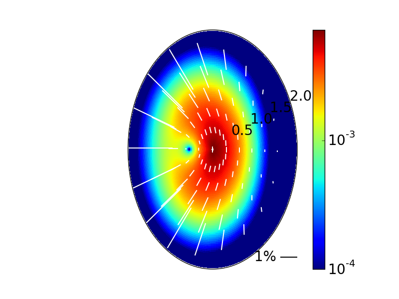
In Fig. 7, we plot the distribution of the polarized intensity together with polarization vectors for the large grain case of mm. There are several features that are worth noting. First, unlike the Rayleigh scattering case, the polarized intensity is no longer symmetric with respect to the major axis. This is because large, mm/cm sized, grains preferentially scatter light in the forward direction (e.g., Bohren & Huffman 1983), making the side of the disk closer to the observer (the right half) brighter. The polarization fraction is, however, higher on the far side (especially toward the outer part of the disk) because the polarization degree of the scattered light is higher for backward scattering than for forward scattering (see Fig. 6). The most striking difference between this case and the Rayleigh scattering case shown in Fig. 5 lies in the polarization direction. The difference comes from the polarization reversal in the large grain case, which yields an intrinsic (or face-on) polarization direction in the radial (as opposed to azimuthal) direction and an inclination-induced polarization along the major (rather than minor) axis. The interplay between the intrinsic and inclination-induced polarization leads to polarization directions in the region of high polarized intensity (the most easily observable part) completely different from those observed in HL Tau (see Fig. 1).
We are therefore left with an interesting conundrum. The polarization pattern in the HL Tau disk is suggestive of Rayleigh scattering by relatively small dust grains (although still much larger than the typical ISM grains), but such grains may have difficulty reproducing the observed opacity spectral index (). The index can be reproduced more easily with larger, mm/cm sized, grains, but it is difficult to generate the observed polarization pattern with such grains through scattering. It is conceivable that there are two populations of dust grains, with one responsible for polarization, the other for . The two populations do not have to be located co-spatially in the disk; for example, large grains responsible for the bulk of the unpolarized continuum (and thus ) may have settled close to the midplane, whereas smaller grains that dominate the polarized millimeter radiation may remain floating higher up above the midplane (e.g., Dullemond & Dominik 2004; Tanaka et al. 2005; Balsara et al. 2009 ). If this speculation turns out correct, polarized emission in millimeter would provide a powerful probe of not only grain growth, but also the expected vertical stratification of grain sizes, especially in conjunction with observations of optical/IR polarization, which probe even smaller, micron-sized, grains that are higher up still above the disk midplane.
5 Other Sources and Future Directions
As mentioned in § 1, spatially resolved polarized sub-mm/mm emission was observed in two other sources besides HL Tau: IRAS 16293-2422B (Rao et al., 2014) and L1527 (Segura-Cox et al., 2015), using SMA and CARMA respectively. We discuss whether the polarization in these two sources is compatible with an origin in dust scattering.
The L1527 disk is nearly edge-on, with an inclination angle . Its 1.3 mm dust emission was observed to be polarized at level, with a direction roughly perpendicular to the disk (i.e., along the minor axis). This pattern is consistent with that expected from dust grains aligned by a predominantly toroidal magnetic field (Segura-Cox et al., 2015). It is also the pattern expected of scattering by relatively small dust grains in the Rayleigh limit because the polarization induced by disk inclination is along the minor axis (as illustrated vividly in the lower right panel of Fig. 2). Indeed, the fraction of the scattered radiation that is polarized due to disk inclination increases with the inclination angle, reaching a maximum value of for edge-on disks, as we showed analytically in § 2.2 (see eq. (18)). This trend makes it more likely for L1527-like disks to show scattering-induced polarization than face-on disks. Indeed, the median polarization fraction of L1527 is the highest among the three sources with spatially resolved sub-mm/mm polarized emission so far. However, whether such polarization can actually be observed or not depends on the polarized intensity, which in turn depends on the total intensity and the polarization fraction (relative to the total intensity). The latter is sensitive to the scattering opacity , which depends on the dust properties, especially the grain size, which can vary greatly from one source to another. To produce the observed polarization fraction of in L1527 through scattering, the grains must have grown well beyond size; otherwise, the scattering opacity would be too small. The scattering cannot be dominated by large, mm/cm sized grains either. Such grains would produce polarization along, rather than perpendicular to, the edge-on disk because of polarization reversal (see § 4.2 and Figs. 6 and 7). Large cm-sized grains are inferred in the L1527 disk from the small opacity spectral index (Tobin et al., 2013). If the observed polarization is due to scattering by sub-mm sized grains, then two grain populations may again be needed, as in the HL Tau case discussed in § 4.2.
The disk in IRAS 16293-2422B appears to be nearly face-on (Rodriguez et al., 2005; Zapata et al., 2013). Its 0.88 mm emission was observed to be polarized at level, with the polarization directions showing a swirling pattern that is neither strictly radial nor purely azimuthal (Rao et al., 2014). Rao et al. showed that the pattern is broadly consistent with the polarized emission expected from grains aligned by a magnetic field that is warped into a spiral configuration by disk rotation, although the rotation is hard to measure directly because of the face-on orientation. It is inconsistent with the simplest dust scattering model for axisymmetric face-on disks, where the polarization directions are expected to be perfectly azimuthal, as illustrated in the upper left panel of Fig. 2. However, the observed polarized intensity is arc-shaped which, for face-on systems, requires intrinsically non-axisymmetric disk models, such as those constructed by Kataoka et al. (2015a). Indeed, the observed intensity distribution is reminiscent of the lopsided ring models of Kataoka et al. (see their Fig. 6 and 7), although the polarization direction in the models changes sharply from radial in the inner part of the ring to azimuthal in the outer part. It is conceivable that dust scattering models with more complicated disk structures, such as spiral arms, may match the observation better, but this remains to be demonstrated. One worry is that the dust emission in this source may be optically thick at sub-mm wavelengths (Zapata et al., 2013), which would reduce the degree of anisotropy in the unpolarized radiation to be scattered, and thus the degree of polarization in the scattered radiation (Kataoka et al., 2015a). Another is that the polarized emission detected in this deeply embedded source may be contaminated by the protostellar envelope. Higher resolution ALMA polarization observations should become available in the near future. They will provide more stringent tests of the dust scattering model of polarized mm/sub-mm emission.
As stressed by Kataoka et al. (2015a), polarized radiation at mm/sub-mm wavelengths provides a powerful probe of grain growth, if it is produced by dust scattering. A robust prediction of the scattering model is that large, mm/cm-sized, grains should produce millimeter polarization along the major axis of an inclined disk due to polarization reversal, especially in the central region where the intrinsic (face-on) polarization is expected to be weak and the observed polarization pattern is more easily dominated by that induced by disk inclination (see Fig. 7 for an illustration). This effect should be searched for with high resolution ALMA observations, especially in high-inclination systems. Another way to probe large grains is to observe polarization at longer, centimeter, wavelengths using, for example, JVLA and the future SKA. At such wavelengths, the scattering by mm-sized grains would still be in the Rayleigh regime, with a high degree of polarization of the scattered light. Given the sensitive dependence of the scattering opacity (which controls the polarization fraction of the total intensity) on the grain size relative to the wavelength, it is important to carry out high-resolution polarization observations at multiple wavelengths to determine whether the polarization is indeed due to dust scattering and, if yes, to constrain the grain size distribution. With the polarization capability of JVLA, and that of ALMA coming online soon, the prospect for using sub-mm/mm/cm polarization to probe grain properties in disks is bright on the observational side.
On the theoretical side, much work remains to be done. In this paper, we have limited our treatment to the simplest case of optically and geometrically thin disk, to bring out the essential features of the disk inclination-induced polarization transparently through a semi-analytic model. As noted earlier, there is indication from the spatial distribution of the opacity spectral index that part of the HL Tau disk is optically thick at sub-mm/mm wavelength, including the central continuum peak, B1 and B6 rings, at radii of , 20, and 81 AU, respectively (ALMA Partnership: Brogan et al., 2015). Since the B6 ring is rather narrow, and the bulk of polarized emission is detected interior to it, it should not affect our HL Tau model much. The continuum peak and B1 ring are not resolved by the polarization observation, but they can potentially lower the polarization fraction in the central pixel relative to the outer part, which is expected to bring the dust scattering model presented in § 3 and Fig. 5 into closer agreement with observation444The polarization fraction of millimeter emission in the central region can also be lowered if the grains there grow to centimeter sizes, which can contribute significantly to the total but little to the polarized intensity.. The effects of optically thick regions, as well as substructures on the disk such as rings and gaps, need to be quantified in future calculations in order to compare with higher resolution ALMA polarization observations that should become available soon.
Another future improvement is to relax the thin disk approximation. While the approximation is adequate for large grains that have settled close to the disk midplane, it would be less so for smaller grains that remain higher up above the midplane. It is likely that there is a gradient in dust grain concentration and size distribution in all three (radial, vertical and azimuthal) directions through grain growth, inward drift, vertical settling, and trapping (see Testi et al. 2014 for a recent review, and Pérez et al. 2012 for an example of gradient in grain size). Such gradients should be taken into account in more complete models of scattering-induced polarization, perhaps using 3D radiative transfer codes such as RADMC3D. As noted earlier, in HL Tau and L1527, the observed opacity spectral index and polarization pattern in millimeter, if originating from dust scattering, appear to require two grain populations of different size distributions. Whether they can arise naturally through grain evolution in the disk warrants further investigation. In addition, a complete model of disk polarization at sub-mm/mm/cm will need to include both the polarized emission by aligned, non-spherical grains (particularly grains of tens of microns in size or larger, although it is unclear whether such grains can be aligned with respect to the magnetic field or not, as discussed in § 1) and dust scattering, and possible interplay between the two.
6 Conclusions
Motivated by the recent spatially resolved millimeter polarization observations of the HL Tau disk, we have developed a simple semi-analytic model for the dust scattering-induced polarization in the limit of optically and geometrically thin disk and Rayleigh scattering, with an emphasis on the effects of the disk inclination to the line of sight. The main results are summarized as follows:
1. We developed an efficient approximate method for computing disk polarization from dust scattering by dividing the source region of the millimeter radiation to be scattered at a location inside the disk into two conceptually distinct parts: a near-field region centered on the location with a size comparable to the local dust scale-height, and a far-field region outside. Radiation from the near-field region is more or less isotropic, and does not contribute significantly to the polarization of the scattered light. Radiation from the far-field region is concentrated toward the disk plane. It is strongly polarized after scattering in an inclined disk. The polarization fraction of the scattered light increases with the inclination angle, reaching a maximum value of for edge-on disks if the incoming radiation to be scattered is azimuthally isotropic in the disk plane (eq. (18)). The polarization induced by disk inclination is parallel to the minor axis. It can easily dominate the intrinsic polarization of the disk in the face-on view (see Fig. 2).
2. We developed a simple model for the polarization of the HL Tau disk, based on the(Kwon et al., 2011) model of disk physical structure and polarization induced by a disk inclination of (see Fig. 5). The model naturally reproduces two main features of HL Tau: (1) the region of high polarized intensity is elongated along the major axis, and (2) the polarization vectors in this region are roughly parallel to the minor axis. Both are the consequences of a simple geometric effect: only the radiation propagating along the major axis of a tilted disk would be scattered by 90∘ to reach the observer and be maximally polarized, with a polarization direction along the minor axis in the plane of the sky. The broad agreement is robust because it does not depend on the detailed properties of dust grains (which are uncertain) as long as the scattering is in the Rayleigh limit. It provides support for the millimeter polarization observed in this particular case originating at least in part from dust scattering, although polarized emission from magnetically aligned dust grains cannot be ruled out, especially if the disk field is more complex than toroidal.
3. For the other two cases with observed mm/sub-mm polarization, L1527 and IRAS 16293-2242B, the situation is less clear. The observed polarization pattern in the nearly edge-on disk of L1527 is compatible with that expected of either toroidal field-aligned grains or dust scattering. The pattern observed in the possibly face-on disk of IRAS 16293-2242B is more consistent with that expected of grains aligned by a rotationally warped magnetic field than with the simplest case of dust scattering. Higher resolution observations of more disks with different inclination angles are needed to better differentiate the grain-alignment and dust-scattering models. The observational situation should improve drastically with ALMA and JVLA.
4. To reproduce the polarization fraction of observed at 1.3 mm in the HL Tau disk, a maximum size of tens of microns is needed for the scattering grains. Such grains are generally thought to be too small to produce an opacity spectral index of order 1 or less that is observed in HL Tau and other sources; larger, mm/cm sized grains may be needed. However, mm/cm sized grains tend to produce polarization parallel (rather than orthogonal) to the major axis due to polarization reversal (see Figs. 6 and 7), which is not observed in HL Tau; nevertheless, this pattern should be searched for in other sources as a robust indicator for large grains. In any case, the dust scattering model for polarization and the relatively low produce an interesting conundrum that needs to be resolved in the future, perhaps with more complete models that include grain evolution and 3D radiative transfer, as well as polarized direct emission from aligned grains. Such models, together with the high resolution ALMA/JVLA polarization observations that will soon become available, should make it possible to disentangle the contributions of grain alignment and dust scattering to the disk polarization, which is needed in order to provide robust constraints on the magnetic field that is generally thought to be crucial to the dynamics and evolution of protoplanetary disks and/or the grain growth that may eventually lead to planet formation.
Acknowledgements
We thank Phil Arras, Dom Pesce, Scott Suriano, and Laura Pérez for helpful discussion. LWL acknowledges support by NSF AST-1139950. HFY and ZYL are supported in part by NSF AST-1313083 and NASA NNX14AB38G.
References
- Alecian (2013) Alecian E. 2013, Environments of the Sun and the stars, Lecture Notes in Physics, Springer-Verlag Berlin Heidelberg, 857, 183
- ALMA Partnership: Brogan et al. (2015) ALMA Partnership, Brogan, C. L., Pérez, L., et al. 2015, ApJ, 808, L3
- Balsara et al. (2009) Balsara, D. S., Tilley, D. A., Rettig, T., & Brittain, S. D. 2009, MNRAS, 397, 24
- Bohren & Huffman (1983) Bohren, C. F. & Huffman, D. R. 1983, Absorption and scattering of light by small particles. Wiley New York NY
- Canovas et al. (2013) Canovas, H., Menard, F., Hales, A., et al. 2013, A&A, 556, A123
- Cho & Lazarian (2007) Cho, J. & Lazarian, A. 2007, ApJ, 669, 1085
- Draine (2006) Draine, B. T. 2006, ApJ, 636, 1114
- Dullemond & Dominik (2004) Dullemond, C. P. & Dominik, C. 2004, A&A, 421, 1075
- Hoang & Lazarian (2009) Hoang, T., & Lazarian, A. 2009, ApJ, 697, 1316
- Kataoka et al. (2015a) Kataoka, A., Muto, T., Momose, M., et al. 2015a, ApJ, 809, 78
- Kataoka et al. (2015b) Kataoka, A., Muto, T., Momose, M., et al. 2015b, preprint (arXiv:1507.08902)
- Kirchschlager & Wolf (2014) Kirchschlager, F. & Wolf, S. 2014, A&A, 568, A103
- Kwon et al. (2011) Kwon, W., Looney, L. W., & Mundy, L. G. 2011, ApJ, 741, 3
- Kwon et al. (2015) Kwon, W., Looney, L. W., Mundy, L. G. & Welch, W. J. 2015, 808, 102
- Lazarian (2007) Lazarian, A. 2007, J. Quant. Spectrosc. Radiative Transfer, 106, 225
- Mathis et al. (1977) Mathis, J. S., Rumpl, W., & Nordsieck, K. H. 1977, ApJ, 217, 425
- Min et al. (2005) Min, M., Hovenier, J. W., & de Koter, A. 2005, A&A, 432, 909
- Murakawa (2010) Murakawa, K. 2010, A&A, 518, A63
- Pérez et al. (2012) Pérez, L. M., Carpenter, J. M., Chandler, C. J., Isella, A., Andrews, S. M., & Ricci, L. et al. 2012, ApJL, 760, L17
- Pollack et al. (1994) Pollack, J. B., Hollenbach, D., Beckwith, S., et al. 1994, ApJ, 421, 615
- Rao et al. (2014) Rao, R., Girart, J.M., Lai, S-P., & Marrone, D. P. 2014, ApJ, 780, L6
- Rodriguez et al. (2005) Rodriguez, L. F., Loinard, L., D’Alessio, P., et al. 2005, ApJ, 621, L133
- Ricci et al. (2012) Ricci, L., Trotta, F., Testi, L., et al. 2012, A&A, 540, A6
- Segura-Cox et al. (2015) Segura-Cox, D. M., Looney, L. W., Stephens, I. W., et al. 2015, ApJ, 798, L2
- Stephens et al. (2014) Stephens, I. W., Looney, L. W., Kwon, W., et al. 2014, Nature, 514, 597
- Tanaka et al. (2005) Tanaka, H., Himeno, Y., & Ida, S. 2005, ApJ, 625, 414
- Testi et al. (2014) Testi, L., Birnstiel, T., Ricci, L., et al. 2014, Protostars and Planets VI, 914, 339
- Tobin et al. (2013) Tobin, J., Hartmann, L., Chiang, H-F., et al. 2013, ApJ, 771, 48
- Verhoeff et al. (2011) Verhoeff, A. P., Min, M., Pantin, E., et al. 2011, A&A, 528, A91
- Zapata et al. (2013) Zapata, L. A., Loinard, L., Rodriguez, L. F., et al. 2013, ApJ, 764, L14