Phase transition in symmetric active plasmonic systems
Abstract
Surface plasmon polaritons (SPPs) are coherent electromagnetic surface waves trapped on an insulator-conductor interface. The SPPs decay exponentially along the propagation due to conductor losses, restricting the SPPs propagation length to few microns. Gain materials can be used to counterbalance the aforementioned losses. We provide an exact expression for the gain, in terms of the optical properties of the interface, for which the losses are eliminated. In addition, we show that systems characterized by lossless SPP propagation are related to symmetric systems. Furthermore, we derive an analytical critical value of the gain describing a phase transition between lossless and prohibited SPPs propagation. The regime of the aforementioned propagation can be directed by the optical properties of the system under scrutiny. Finally, we perform COMSOL simulations verifying the theoretical findings.
pacs:
I Introduction
A light-matter interaction called surface plasmon polaritons (SPPs) has gained the scientists’ interest due to its unique properties, such as control of electromagnetic energy in subwavelength scales SPPsubOptics ; review2005 ; kaxirasNano2014 ; huang2007 , high sensitivity in dielectric properties kaxirasNano2014 ; LL1 ; LL2 , negative refraction and hyperbolic wave front negRef ; selffocus . SPPs have been applied in nanophotonics, imaging, optical holography, nano antennas, biosensing, integrated circuits and metamaterials LL2 ; nanoAntennas ; holography ; biosense1 ; biosense2 . Important progress has been made in plasmonics with two-dimensional materials, such as graphene and black phosphorus, where the plasmonic properties can be tuned by using chemical doping or applying external gate voltage kaxirasNano2014 ; graphenePRB ; grapheneNatPhot2012 ; basovNanoLet2011 ; basovNatLet2012 ; reviewIEEE2013 ; prl2014BF . Moreover, plasmonic lenses, waveguides and meta-materials based on graphene have already been applied kaxirasNano2014 ; teraPRB ; enghetaSc2011 . Last but not least, multi-layers structures have been created by stacking two-dimensional crystals one on top of another providing surprising electronic and optical features prl2014BF ; grapheneNatPhot2012 ; grapSheetAPL .
Near plasma frequency , the electrons on the surface of metals or semiconductors are free to move sustaining collective oscillations review2005 ; economou ; gainOSA2004 ; maier ; valag2009 ; valag2011 . The coupling between light and electron oscillations allows the creation of Transverse Magnetic (TM) Electromagnetic (EM) surface waves, namely surface plasmon polaritons (SSPs). From the mathematical point of view, SPPs are surface waves bounded along the interface between two materials with sign reversed dielectric permittivities, i.e. a dielectric-conductor interface, and their EM field decays exponentially away from the interface (evanescent waves) review2005 ; economou ; gainOSA2004 ; maier ; valag2009 ; valag2011 .
In this work, we focus on plasmonic waveguides formed by a planar interface which consists of two semi-infinite layers with reversed sign permittivities, namely a dielectric and a metal. The dispersion relation which characterizes the SPPs propagation can be determined by Maxwell Equations (ME) as review2005 ; gainOSA2004 ; huang2007 ; maier
| (1) |
where is the free space wave number of the incident excitation light of angular frequency , is the plasmon effective refractive index, and the permittivity of dielectric and metal, respectively, and is the speed of light in vacuum.
SPPs decay exponentially along the interface as well, due to the metal losses. In mathematical language, the metal losses are described by a negative imaginary part in the permittivity function of the metal, i.e. , where . Consequently, the SPPs wave number becomes complex, viz. , where the imaginary part accounts for losses of SPPs energy. The imaginary part of Eq. (1) determines the characteristic propagation length , which shows the rate of change of the energy attenuation of SPPs along the propagation axis gainOSA2004 ; maier ; huang2007 , that is
| (2) |
Gain materials, rather than passive dielectrics, have been used to reduce the losses in SPPs propagation. These active materials are characterized by a complex permittivity function, i.e. with , where the imaginary part accounts for gain, that is, the dielectrics give energy to the system counterbalancing the metal losses gainOSA2004 ; huang2007 ; avrPRB2004 ; leonNatPho2010 ; leonNatPhot2012 . In addition, active dielectrics have been used for exploring symmetry in optical systems huang2014 ; lupu2011 ; lupu2013 ; ptPRA2014 characterized by the condition that , where and the refractive index and its complex conjugate, respectively; denotes the spatial coordinate along the interface. Metamaterials with symmetric effective refractive index can be constructed by the combination of gain dielectrics and loss metals lupu2011 ; lupu2013 ; ptPRA2014 . What makes symmetric media interesting is that they allow control over EM field by tuning the gain and loss of the materials.
It has been already demostrated in gainOSA2004 ; huang2007 ; leonNatPho2010 ; leonNatPhot2012 that for a certain value of gain, the losses in SPPs propagation may vanish. Consequently, the SPPs propagation constant as well as the effective refractive index n become real and therefore the symmetry is satisfied, since does not exhibit any spatial dependence along the interface. Furthermore, Eq. (1) states that a symmetric leads to infinite propagation length, viz. lossless SPPs propagation.
In the present work, we investigate theoretically and numerically the symmetry in active plasmonic systems. In Section II, we provide an explicit expression of the gain, namely , for which the losses in SPPs propagation have been eliminated. In addition, we find a critical value of , where SPPs wave number and the effective SPPs refractive index shift from real to imaginary regime, subsequently the is a symmetry breaking point. It is remarkable that it is a steep phase transition from lossless to prohibited SPP propagation, which offers the opportunity to control whether SPPs propagate or not by tuning the optical properties of the interface. In Section III, we apply the theoretical results derived in the previous Section on interfaces comprised of active dielectrics and Drude metals. In Section IV, we proceed with numerical simulations by solving the full system of ME in the frequency domain by using the commercial multiphysics software COMSOL, and we show that lossless SPPs propagation corresponding to symmetry can be achieved in the presence of gain dielectrics. Finally, concluding remarks are offered in Section V.
II and critical gain
In this Section, we calculate the exact expression of the dielectric permittivity gain counterpart , for which the SPPs propagate without losses in the dielectric-metal interface.
Plugging the complex structure of the dielectric and metal permittivity into Eq. (1), function can be written in the ordinary complex form as bookComplexSqrt
| (3) |
where is the discontinuous signum function and
| (4a) | |||
| (4b) | |||
with denoting the norm of the complex number .
Considering the plasmon effective index in Eq. (3) in the –plane, we observe that a lossless SPP propagation, i.e, , is warranted when the conditions and are simultaneously satisfied. For and , although the imaginary part in Eq. (3) vanishes due to the signum function, its real part becomes imaginary, i.e. , which does not correspond to propagation SPP modes. Studying the permittivity dependence of and in Eq. (4) and solving the condition with respect to the dielectric gain part for , we obtain two exact solutions, i.e., of the form
| (5) |
The result in Eq. (5) is in agreement with the one derived in Refs. gainOSA2004 ; huang2007 following yet a different derivation path. Invoking the physical argument of the SPP wave bound to the dielectric-metal interface, we read that only is of physical relevance, since leads to waves radiating in the transverse towards the interface direction gainOSA2004 . Taking into account the, by definition, positive real domain of and the dependence of the latter on the metal-dielectric components, we read that the following inequality has to be satisfied
| (6) |
For both and diverge exhibiting asymptotically the same image, thus
| (7) |
This in turn means that the former complex point does not belong to the set domain of the lossless SPP propagation since .
Solving, on the other hand, the equation with respect to the dielectric gain for , we may determine the critical value distinguishing the regimes of lossless and prohibited SPP propagation, namely
| (8) |
Equating Eqs. (5) and (8), i.e., , we obtain the condition which reduces to , since . Replacing the former value of in Eqs. (5) and (8) we obtain and for and , respectively. The former case is obviously a contradiction. The latter case corresponds to the singularity point in Eq. (7), where , thus it is a contradiction as well. In other words, and do not become zero simultaneously, implying that the critical value is not an element of the domain set of the wave number . This is in agreement with the propagation length in Eq. (2). Indeed, when then tends to infinity, which means that the SPP wave number must exhibit a nonzero value. An even more interesting point, unveiled from the analysis, is the estimation of the behaviour when approaching the critical point, ( and ), described by Eq. (7) for with . Physically, the former point corresponds to the wave electrostatic character of zero phase velocity, known in literature as the surface plasmon mode maier . Including the discontinuity at the point , the entire codomain of is described as follows
| (9) |
In the general case of , where (excluding the point ) may take nonzero values as well, we observe the following. For , the signum function in Eq. (3) is negative since then implying . This means that the imaginary part of accounts for losses and the SPP amplitude decreases along the propagation surface. Reversely, for yielding , we have . In this case the imaginary part of accounts for gain and the SPPs amplitude increases along the propagation surface. In the special case of studied above, the SPP amplitude is constant along the propagation surface. This behaviour of the signum function fully explains the results observed in Ref. gainOSA2004 regarding the SPP amplitude.
An interesting feature of the lossless SPP propagation case, i.e., for , in regard to the refractive index is that the latter fulfils the condition , since its imaginary part vanishes owing to the signum function. This in turn, may be considered as the symmetry phase condition, where is spatial independent. However the structure is not symmetric in the narrow sense, the real value of the supported propagation constant along the interface admits time-reversal and geometrical symmetry. Then, the dielectric gain expression in Eq. (5) can be attributed to the symmetry property satisfied by the lossless SPP propagation and denoted as . We shall keep this denomination in what follows. On the contrary, in the case , the condition is not satisfied, since the refractive index is imaginary. Subsequently, the critical gain may be regarded as the -symmetry breaking point of the plasmonic system under scrutiny.
III Active dielectric - Drude metal interface
It is quite remarkable that as well as depend on the optical properties of the dielectric and metal, that is, , and . The metal permittivity in turn may generally exhibit a dependence on the angular frequency , so that by tuning we may control the values of lying below or above . Precisely, for interfaces comprised of an active dielectric and a Drude metal maier , is given as
| (10) |
where denotes the high frequency permittivity, is the plasma frequency and accounts for metal losses in frequency units maier .
By virtue of Eq. (10) we can express the and in terms of the frequency . Moreover, taking Eq. (7) into consideration, we may obtain the SPP resonance frequency review2005 ; maier ; huang2007
| (11) |
It can be proven that for Drude metals the is always smaller than for frequencies lower than . Thus, according to our theoretical results we anticipate lossless SPPs propagation for and prohibited SPPs propagation for .
In order to verify our theoretical predictions, we calculate the SPP dispersion relation for an interface consisting of silver with , , and silica glass with and . The frequency values are confined in the regime imposed by the inequality in Eq. (6). In Fig. 1 we plot the real (dotted blue line) and imaginary (orange dashed line) part of the normalized SPP dispersion relation () with respect to the normalized frequency ; the yellow dash-dot line shows the wave number (-number) in the dielectric, and the resonance frequency is represented by the horizontal green solid line where the interchange between and appears. We observe, indeed, that for the imaginary part of vanishes while for the SPPs wave number is purely real. Subsequently, in the vicinity of a phase transition from lossless to prohibited SPPs propagation is expected (see Section IV).
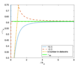
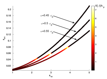
Fig. 1 highlights the relation between and the metal permittivity, and demonstrates the symmetry breaking point , where the vanishes. In Fig. 2 we consider a variable and record the dependence on it of both the magnitude in Eq. (1) and in Eq. (5) for three different frequencies, namely . The former is represented by color lines on the complex plane defined by for and axis, respectively. Each color line corresponds to a different frequency. Fig. 2 unveils that the more dense the dielectric is the higher value of the gain we need for having undamped SPPs propagation. In addition, the vanishes very suddenly as we increase the gain, verifying that at this point the symmetry breaks and the SPPs propagation becomes prohibited. According to the aforementioned figure we can tune the magnitude of the as well as and by choosing the appropriate dielectric.
IV Simulations
In this Section, we verify our theoretical predictions of Sections II and III, by solving numerically the full system of ME in the frequency domain in a two dimensional space (2D) for TM polarization electric and magnetic fields. The numerical experiments have been performed by virtue of the multi-physics commercial software COMSOL. Precisely, we explore the SPPs propagation length with respect to on the interface between two semi-infinity layers, i.e., an active dielectric and a Drude metal, recording the desired phase transition from lossless to prohibited SPP propagation. We further demonstrate the lossless SPPs propagation, analysing the magnetic field intensity along the surface of two known in literature configurations, the Kretschmann-Raether and the Otto configurations review2005 ; maier ; leonNatPhot2012 . In our numerical experiments the frequency is confined in the range with the integration step .
Regarding the active dielectric – Drude metal interface described in the previous section, we conduct the near-field excitation technique maier ; basovNanoLet2011 ; basovNatLet2012 to excite SPPs on the metallic surface. For this purpose, a circular EM source of radius has been located above the metallic surface acting as a point source, since the wavelength of the EM wave in the silica glass is constrained to maier . In addition, Perfectly Matched Layers (PML) are used as boundary conditions.
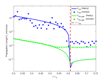
In Fig.3 we demonstrate, in a log-linear scale, the propagation length with respect to subject symmetry (blue line and open circle). For the sake of comparison, we plot for the gainless case (green line and filled circles). The solid lines represent the theoretical predictions obtained by Eq. (2), whereas the circles indicate COMSOL results. For the numerical calculations, the characteristic propagation length has been estimated by the inverse of the slope of the , where is the magnetic intensity along the interface review2005 ; maier ; mariosSPP . The red vertical dashed line denotes the SPP resonance frequency , in which the phase transition appears. The graphs in Fig. 3 indicate that in the presence of the gain, i.e. , the SPPs may travel for very long, practically infinite, distances. Approaching the resonance frequency , decreases rapidly leading to a steep phase transition on the SPPs propagation. The deviations between theoretical and numerical results in Fig. 3 for frequencies near or greater than are attributed to the fact that in the regime , there are quasi-bound EM modes maier , where EM waves are evanescent along the metal-dielectric interface and radiate perpendicular to this. Consequently, the observed EM field for does not correspond to SPPs but belongs to the quasi-bound modes.
So far, the theoretical findings in Sections II and III have been successfully confirmed. We further proceed investigating the symmetry in active plasmonic systems. We perform COMSOL simulations based on the Total Internal Reflection (TIR) method, applied on the Kretschmann-Raether and Otto configurations, separately. Within the former, a thin metal film is sandwiched between two dielectrics with the incident wave hitting the denser medium. In Otto configuration, the denser the dielectric and the metal sandwich a lighter dielectric. In both configurations a type of silica glass, with dielectric constant , is used as denser passive dielectric, whereas for active dielectric (lighter medium) as well as for metal, we use the materials described in Section III. Furthermore, for the COMSOL simulations mariosSPP ; altasim , we utilize a monochromatic plane wave source of frequency , amounting to of plasma frequency , and corresponding to a wavelength in the ultraviolet regime. Again, PML are used as boundary conditions.
According to the Eq. (5), the gain for which SPPs propagate without losses is calculated to be . We observe, however, that in the numerical experiments a larger gain is needed (of the same magnitude though), namely , for both configurations. This deviation from the theoretical value can be justified if one takes into consideration that the assumption of semi-infinitely thick metal and dielectric layers composing the interface gainOSA2004 , under which the SPP dispersion relation of Eq. (1) holds true, is experimentally not fully satisfied.
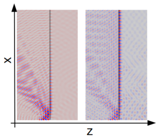
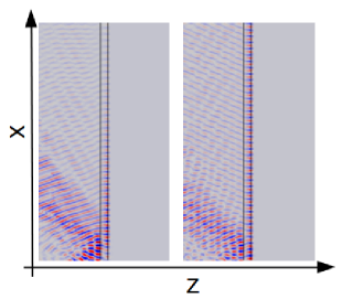
In the Kretschmann-Raether configuration a thin metal of thickness has been used for exciting SPPs. The resulting propagation is illustrated in Fig. 4a under lack of gain and in Fig. 4b for the symmetric case. The corresponding profiles of the magnetic field intensity along the interface are demonstrated in Fig. 5, where the lossless SPP propagation is evident.
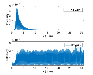
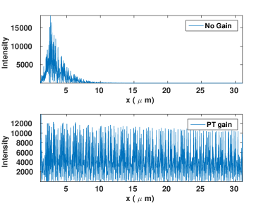
In the Otto configuration, on the other hand, the SPPs excitation is succeeded by means of an active dielectric of thickness which has been used between a non-active dielectric and a metal. By analogy to the Kretschmann-Raether configuration experiment, we present the SPP propagation without gain in Fig. 6(a) and for the gain with in Fig. 6(b). In Fig. 7 the corresponding profiles of the magnetic intensity along the interface are presented, unveiling again a clear lossless SPPs propagation in the case.
V Concluding Remarks
Summarizing, we have investigated the role of active/gain dielectrics in plasmonic systems. In particular, we have studied the propagation properties of surface plasmon polaritons (SPPs) along an interface confined by two semi-infinite layers: a dielectric and a metal. We have calculated an exact expression for the dielectric gain , for which the metal losses have been completely counterbalanced, resulting to lossless SPPs propagation along the interface. We argued that the a plasmonic system characterized by the aforementioned lossless propagation may be related to symmetric systems, i.e., . Within the symmetry, a critical gain exists distinguishing between the real and imaginary part of the SPP dispersion relation. This distinction corresponds to a phase transition from lossless to prohibited SPP propagation. It is remarkable that the as well as the depend on the optical properties of the interface.
We applied our theory to interfaces consisting of Drude metals and gain dielectrics demonstrating the predicted by the theory lossless propagation as well as the phase transition at the SPP resonance frequency . We performed numerical simulations with COMSOL software, using the near-field excitation method in order to investigate our theory, verifying successfully all the theoretical predictions. We also performed COMSOL simulations for two different plasmonic configurations based on the TIR method- Kretschmann-Raether and Otto configurations- where lossless SPP propagation can be achieved.
Active metamaterials may be designed to have the desirable frequency-dependent permittivity response, as Eq. (5) points out; these metamaterials could be used for the fabrication of symmetric plasmonic systems, providing infinite SPPs propagation. The active metamaterials may be used to design symmetric plasmonic integrated circuits which could transfer information in sub-wavelength scales for large (theoretically infinite) distance, rather than a passive plasmonic system where SPPs propagate for few micrometers. Moreover, we demonstrated that there is a threshold in the gain values, above which the symmetry breaks and thus the system passes from lossless to prohibited propagation. The gain threshold as well as the gain depend on the optical properties of the dielectric and metal, subsequently we could control the SPPs propagation by tuning the dielectric constant of metal or the real part of dielectric permittivity ; for instance, the former, i.e. , is usually frequency-dependent, thus we can interchange between lossless and prohibited SPP propagation by tuning the frequency of the incident EM wave.
Acknowledgements
This work was supported in part by the European Union program FP7-REGPOT-2012-2013-1 under grant agreement 316165. In addition it was partially supported by Fondecyt grant 1120123, Programa ICM P10-030-F, the Programa de Financiamiento Basal de CONICYT (FB0824/2008), by the Ministry of Education and Science of the Republic of Kazakhstan (Contract 339/76-2015) and the Ministry of Education and Science of the Russian Federation in the framework of Increase Competitiveness Program of NUST MISiS (No. К2-2015-007).
References
- (1) Barnes WL, Dereux A, Ebbesen TW. Surface plasmon subwavelength optics. Nature. 2003;424(6950):824-30.
- (2) Zayats AV, Smolyaninov II, Maradudin AA. Nano-optics of surface plasmon polaritons. Physics Reports. 2005;408(3-4):131-314.
- (3) Cheng J, Wang WL, Mosallaei H, Kaxiras E. Surface plasmon engineering in graphene functionalized with organic molecules: A multiscale theoretical investigation. Nano Letters. 2014;14(1):50-6.
- (4) Huang C-, Zhu Y-. Plasmonics: Manipulating light at the subwavelength scale. Active and Passive Electronic Components. 2007;2007.
- (5) Liu Y, Zentgraf T, Bartal G, Zhang X. Transformational plasmon optics. Nano Letters. 2010;10(6):1991-7.
- (6) Zentgraf T, Liu Y, Mikkelsen MH, Valentine J, Zhang X. Plasmonic Luneburg and Eaton lenses. Nature Nanotechnology. 2011;6(3):151-5.
- (7) Liu Y, Zhang X. Metasurfaces for manipulating surface plasmons. Appl Phys Lett. 2013;103(14).
- (8) Verslegers L, Catrysse PB, Yu Z, Fan S. Deep-subwavelength focusing and steering of light in an aperiodic metallic waveguide array. Phys Rev Lett. 2009;103(3).
- (9) Huang L, Chen X, Mühlenbernd H, Zhang H, Chen S, Bai B, et al. Three-dimensional optical holography using a plasmonic metasurface. Nature Communications. 2013;4.
- (10) Dorfmüller J, Vogelgesang R, Khunsin W, Rockstuhl C, Etrich C, Kern K. Plasmonic nanowire antennas: Experiment, simulation, and theory. Nano Letters. 2010;10(9):3596-603.
- (11) Friedt J, Francis L, Reekmans G, De Palma R, Campitelli A, Sleytr UB. Simultaneous surface acoustic wave and surface plasmon resonance measurements: Electrodeposition and biological interactions monitoring. J Appl Phys. 2004;95(4):1677-80.
- (12) Bender F, Roach P, Tsortos A, Papadakis G, Newton MI, McHale G, et al. Development of a combined surface plasmon resonance/surface acoustic wave device for the characterization of biomolecules. Measurement Science and Technology. 2009;20(12).
- (13) Jablan M, Buljan H, Soljačić M. Plasmonics in graphene at infrared frequencies. Physical Review B - Condensed Matter and Materials Physics. 2009;80(24).
- (14) Grigorenko AN, Polini M, Novoselov KS. Graphene plasmonics. Nature Photonics. 2012;6(11):749-58.
- (15) Fei Z, Andreev GO, Bao W, Zhang LM, S. McLeod A, Wang C, et al. Infrared nanoscopy of dirac plasmons at the graphene-SiO2 interface. Nano Letters. 2011;11(11):4701-5.
- (16) Fei Z, Rodin AS, Andreev GO, Bao W, McLeod AS, Wagner M, et al. Gate-tuning of graphene plasmons revealed by infrared nano-imaging. Nature. 2012;486(7405):82-5.
- (17) Jablan M, Soljačić M, Buljan H. Plasmons in graphene: Fundamental properties and potential applications. Proc IEEE. 2013;101(7):1689-704.
- (18) Low T., Roldán R., Wang H., Xia F., Avouris P., Moreno L.M., Guinea F. Plasmons and Screening in Monolayer and Multilayer Black Phosphorus. Phys Rev Lett. 2014;113
- (19) Nikitin AY, Guinea F, García-Vidal FJ, Martín-Moreno L. Edge and waveguide terahertz surface plasmon modes in graphene microribbons. Physical Review B - Condensed Matter and Materials Physics. 2011;84(16).
- (20) Vakil A, Engheta N. Transformation optics using graphene. Science. 2011;332(6035):1291-4.
- (21) Wang B, Zhang X, Yuan X, Teng J. Optical coupling of surface plasmons between graphene sheets. Appl Phys Lett. 2012;100(13).
- (22) Economou EN. Surface plasmons in thin films. Physical Review. 1969;182(2):539-54.
- (23) Nezhad MP, Tetz K, Fainman Y. Gain assisted propagation of surface plasmon polaritons on planar metallic waveguides. Optics Express. 2004;12(17):4072-9.
- (24) Maier SA. Plasmonics: Fundamentals and applications. Plasmonics: Fundamentals and Applications. 2007:1-223.
- (25) Valagiannopoulos CA. On smoothening the singular field developed in the vicinity of metallic edges. International Journal of Applied Electromagnetics and Mechanics. 2009; 31: 67–77
- (26) Valagiannopoulos CA. High selectivity and controllability of a parallel-plate component with a filled rectangular ridge. Progress In Electromagnetics Research. 2011; 119: 497–511.
- (27) Avrutsky I. Surface plasmons at nanoscale relief gratings between a metal and a dielectric medium with optical gain. Physical Review B - Condensed Matter and Materials Physics. 2004;70(15):155416,1-155416-6.
- (28) De Leon I, Berini P. Amplification of long-range surface plasmons by a dipolar gain medium. Nature Photonics. 2010;4(6):382-7.
- (29) Berini P, De Leon I. Surface plasmon-polariton amplifiers and lasers. Nature Photonics. 2012;6(1):16-24.
- (30) Huang C, Ye F, Kartashov YV, Malomed B, Chen X. symmetry in optics beyond the paraxial approximation, Optics Letters; 2014: 39: 5443-5446.
- (31) Benisty H, Degiron A, Lupu A, Lustrac AD, Chénais S, Forget S, et al. Implementation of PT symmetric devices using plasmonics: Principle and applications. Optics Express. 2011;19(19):18004-19.
- (32) Lupu A, Benisty H, Degiron A. Switching using PT symmetry in plasmonic systems: Positive role of the losses. Optics Express. 2013;21(18):21651-68.
- (33) Alaeian H, Dionne JA. Parity-time-symmetric plasmonic metamaterials. Physical Review A - Atomic, Molecular, and Optical Physics. 2014;89(3).
- (34) Cooke R. Classical Algebra: Its Nature, Origins, and Uses. Classical Algebra: Its Nature, Origins, and Uses. 2007:1-206 (p.59).
- (35) Athanasopoulos C., Mattheakis M., Tsironis G.P. Enhanced surface plasmon polariton propagation induced by active dielectrics. Excerpt from the Proceedings of the 2014 COMSOL Conference in Cambridge, (2014)
- (36) Yushanov S.P., Gritter L.T., Crompton J.S., Koppenhoefer K.C. Surface Plasmon Resonance. Excerpt from the Proceedings of the 2012 COMSOL Conference in Boston, (2012)