Semiconductor-inspired design principles for superconducting quantum computing
Abstract
Superconducting circuits offer tremendous design flexibility in the quantum regime culminating most recently in the demonstration of few qubit systems supposedly approaching the threshold for fault-tolerant quantum information processing. Competition in the solid-state comes from semiconductor qubits, where nature has bestowed some very useful properties which can be utilized for spin qubit based quantum computing. Here we begin to explore how selective design principles deduced from spin-based systems could be used to advance superconducting qubit science. We take an initial step along this path proposing an encoded qubit approach realizable with state-of-the-art tunable Josephson junction qubits. Our results show that this design philosophy holds promise, enables microwave-free control, and offers a pathway to future qubit designs with new capabilities such as with higher fidelity or, perhaps, operation at higher temperature. The approach is also especially suited to qubits based on variable super-semi junctions.
Spin qubits Awschalom et al. (2013) are based on the fundamental and intrinsic properties of semiconductor systems, such as electron spins trapped in the potential of a quantum dot Loss & DiVincenzo (1998) or a chemical impurity Kane (1998). Spins can be naturally protected from charge noise due to weak spin-orbit coupling. In fact, the tiny matrix element between spin qubit states can allow spin qubits to operate at temperatures above the Zeeman splitting Tyryshkin et al. (2012); Saeedi et al. (2013). While a benefit to qubit coherence, this property of spins also leads to relatively slow single qubit gates via, for example, a microwave pulse. It turns out that nature provides a solution: a very fast and robust two-qubit gate via the exchange interaction. This has led to “encoded” qubit schemes where the qubit is embedded logically in two to four physical spin qubits Petta et al. (2005); DiVincenzo et al. (2000); Bacon et al. (2000). The fact that electrons are real particles can be used for fast initialization and readout techniques. Exchange-only qubits DiVincenzo et al. (2000); Fong & Wandzura (2011) allow all electrical implementation of qubit gate operations and enable universal quantum computation (QC) while providing some immunity to global field and timing fluctuations via a decoherence free subsystem, at the cost of more physical qubits and extra operations per encoded gate.
This work investigates how superconducting (SC) Josephson junction quantum circuits Devoret & Schoelkopf (2013), whose properties can be engineered, can be improved by mimicking some of best properties of spin qubit systems. We propose a first step: an encoded superconducting qubit approach which does not require microwave control, and thus divorces qubit frequency from control electronics. In analogy to the exchange only qubit in semiconductor spin qubit systems, encoded qubits enable microwave-free control of the qubit states via fast DC-like voltage or flux pulses. In contrast to the exchange only qubits, logical gate operations of this encoded SC qubit can be done with minimal overhead (zero overhead in physical 2-qubit gates) in terms of control operations, a surprising result. We describe how to initialize the encoded qubit and implement single- and two-qubit logical gates using only -control pulse sequences (via tunable frequency qubits). In the process we also lay out possible opportunities for future research based on other insights from spin-based QC. To encourage implementation we give an explicit protocol based on qubits in operation today.
Small systems of superconducting qubits based on variations of the transmon qubit Koch et al. (2007); Schreier et al. (2008) have already demonstrated gates with fidelities approaching 99.99% along with rudimentary quantum algorithms including error correction cycles Barends et al. (2013, 2014); Kelly et al. (2015); Reed et al. (2012); Sun et al. (2014); Chow et al. (2014); Córcoles et al. (2015). Note that because these architectures rely on single qubit gates via microwaves, the future design space is constrained by the availability and convenience of microwave generators.
An alternative approach to combining the best properties of semiconductor and superconducting quantum systems is to take advantage of true superconducting-semiconductor systems. The appearance of superconductivity in conventional semiconductors Blase et al. (2009); Bustarret (2015) such as silicon Bustarret et al. (2006); Marcenat et al. (2010); Dahlem et al. (2010); Grockowiak et al. (2013) or germanium Herrmannsdörfer et al. (2009); Skrotzki et al. (2011) could potentially allow for a new type of fully epitaxial super-semi devices Shim & Tahan (2014, 2015). And epitaxial super-semi Josephson juction devices based on the proximity effect have already led to new superconducting circuits Larsen et al. (2015); de Lange et al. (2015). Epitaxial super-semi systems may improve noise properties, but perhaps more importantly they enable gate-tunable Josephson junctions, which we can also take advantage of in our proposal introduced below.
I Results
I.1 From encoded spins to tunable qubits
Spins in quantum dots, say in silicon, are typically assumed to have equivalent g-factors, so that in a magnetic field the frequency of each qubit is the same. Thus, to achieve universal quantum computation (an ability to do arbitrary rotations around the Bloch sphere plus a two-qubit entangling gate), one needs at minimum three spins. In this case, an encoded 1-qubit gate requires around 3 pulses and a CNOT gate requires roughly 20 pulses DiVincenzo et al. (2000), a hefty overhead. 2-qubit encodings are possible, but require the complication of a magnetic field gradient (via for example a micromagnet). Superconducting qubits, on the other hand, can be man-made such that the qubit frequency is tunable. This allows arbitrary one-qubit rotations with just two physical qubits, in theory.
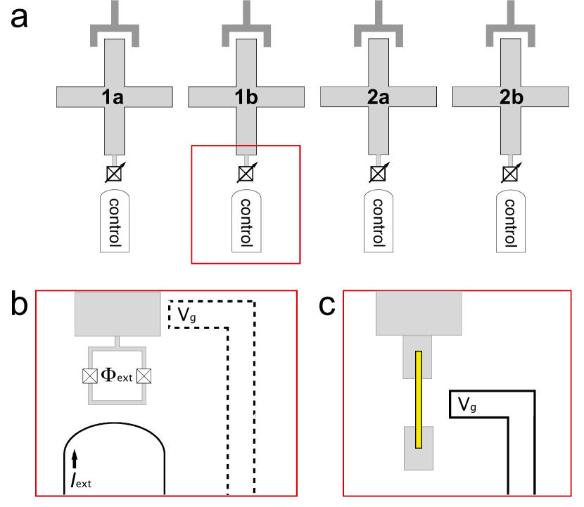
In this work, we consider a qubit encoded in a system of two capacitively coupled SC qubits. We take tunable transmons Reed et al. (2012); Ristè et al. (2015) like xmons Barends et al. (2013) or gatemons Larsen et al. (2015) as our prototypical SC qubits (see Fig. 1a) and suggest one possible implementation following the capacitively-coupled xmon architecture of Martinis et al. Barends et al. (2014) to encourage near-term realization. Although we explicitly chose the xmon geometry to be more specific about our proposed protocol, the general idea can easily be applied to other types of SC qubits, such as traditional transmons or capacitively-shunted flux qubits You et al. (2007); Yan et al. (2015), which we will discuss later. A transmon qubit Koch et al. (2007) is described by the charge qubit Hamiltonian
| (1) |
where = is the electron charging energy for total capacitance and is the Josephson energy. and are the number and phase operators, respectively, and is the gate charge number that can be tuned by a capacitively-coupled external voltage. The qubit frequency = where is the energy difference between the first excited state and the ground state, and in the transmon regime, . The Josephson energy of a JJ is determined by the material properties and geometry of the JJ, but a double JJ can be considered as a tunable JJ Makhlin et al. (1999) where an externally applied magnetic flux through the double JJ loop can tune the effective coupling energy = (see Fig. 1b). is the external magnetic flux and is the SC flux quantum. Individual transmon qubits are typically controlled by tuning the qubit frequency with tunable for control and by applying microwaves for control.
Recently, there has been progress in an alternative approach for a tunable JJ using a superconductor proximitized semiconductor weak link junction Larsen et al. (2015); de Lange et al. (2015). In Ref. Larsen et al. (2015), an InAs nanowire was used to connect two superconductors (Al). The nanowire was epitaxially coated with Al and a small portion of the wire was etched off to form a semiconductor nanowire bridging two SCs (Fig. 1c). A side-gate voltage was used to tune the carrier density under the exposed portion of the wire and thus the Josephson energy of this SNS JJ. The gatemon, a tunable transmon based on this gate-tunable JJ, has several advantages. It requires only a single JJ that can be quickly tuned by a electrostatic voltage. It removes the need for external flux, and hence reduces dissipation by a resistive control line and allows the device to operate in a magnetic field. The epitaxial growth of the nanowire JJ and its clean material properties Chang et al. (2015); Krogstrup et al. (2015) demonstrate the potential of a bottom-up approach for SC quantum devices Shim & Tahan (2014, 2015).
Our encoded qubit is defined in a two-transmon system. The Hamiltonian for two transmons with the capacitive coupling is
| (2) | |||||
where is the capacitive coupling energy and (=) is the Pauli operator for the -th transmon in a reduced subspace of transmon qubit states. is the qubit energy of the -th transmon, and = with = where and are the two lowest energy states of individual transmons. In transmon qubit systems, the capacitive coupling is usually turned on (off) by tuning the qubit frequencies to on (off) resonance. The capacitive coupling conserves the parity of the two transmon system, and the Hamiltonian [Eq. (2)] is block-diagonal in the basis of . We define our encoded qubit in the subspace of , since the other subspace has states with a very large energy difference (much larger than the capacitive coupling), effectively turning off the capacitive coupling all the time.
In the encoded qubit basis where
| (3) |
the single qubit Hamiltonian is
| (4) |
where = and (=) is the Pauli operator for the encoded qubit. The qubit energies and can be controlled by the tunable JJ of each tunable transmon or gatemon, enabling logical gate operations with only fast DC-like voltage or flux pulses. In the following we will describe the logical gate operations, initialization, and measurement schemes for this encoded qubit architecture.
I.2 Single qubit operations
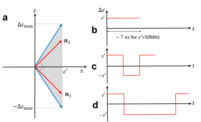
The Hamiltonian for an encoded qubit is given by Eq. (4). For a fixed capacitive coupling between SC qubits, is fixed, and the single qubit operations can be implemented by pulsing the qubit energy through the -control of individual transmons, in at most three rotations. Since the tunable range of (order of GHz) is much greater than (tens or hundreds of MHz), the rotation axis can be in almost any direction in the right half of the plane (see Fig. 2a), and most logical single qubit gates can be implemented in two rotations Shim et al. (2013). In general, all single qubit gate operations can be implemented as a three-step Euler angle rotations around two orthogonal rotation axes (e.g. see the two red axes in Fig. 2a).
We now provide implementations for a few representative single qubit gates. The Hadamard gate, =, is a single qubit gate that is almost ubiquitous in quantum circuits. Figure 2b shows an implementation of gate as a single rotation = around =. It can be achieved by tuning =. Here is a rotation by angle around axis. Pauli gate can be realized as a single rotation by tuning the two xmons on resonance (=0), or three-step rotations such as = where = and =, as was shown in Fig. 2c. gate requires three-step rotations: =. The above examples are for ideal systems with precise control over the system parameters. In real systems with fluctuating parameters, recently developed dynamical error-cancelling pulse sequences Wang et al. (2012, 2014) could be useful for gate operations with higher fidelity.
Given that single qubit gates in transmon systems through -control have already demonstrated fidelities better than 0.999 Barends et al. (2014), we expect the logical single qubit gates (which require at most three rotation steps through control of transmons) will be able to reach a fidelity better than =0.997 using currently available experimental techniques.
I.3 Two qubit operations
For a scalable qubit architecture, we need to plan for the transmon qubit frequencies such that unnecessary resonances are avoided, especially if the two-qubit interaction cannot be completely shut off via, e.g., a tunable coupler Chen et al. (2014). An encoded qubit has two transmons with idle frequency difference much larger than the capacitive coupling, so we can effectively turn the coupling off. In the two encoded qubit system (4 transmon system), we set the idle frequencies of next-nearest neighbor transmons to be different by more than the direct capacitive coupling between them, which is order of MHz (Kelly et al., 2015). We also set the encoded qubit frequencies of the neighboring encoded qubits to be different so we can mitigate some unintended resonances. For the calculations in this section, we set the four transmon qubit idle frequencies as 5.6, 4.6, 5.9, 4.8 GHz for = 1a, 1b, 2a, 2b, respectively [see Fig. 1a]. In this section and the following, we set =375MHz and =30MHz for all transmons. Transmon qubit frequencies are controlled by tuning .
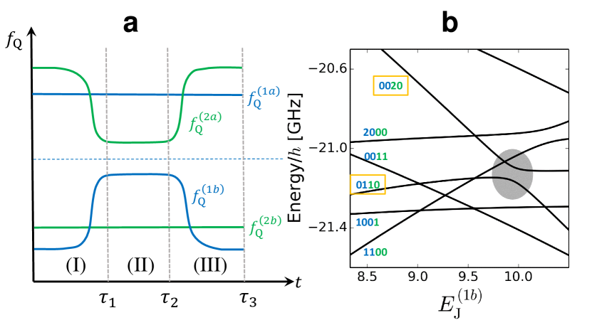
Two qubit operations can be implemented by adopting the adiabatic two-qubit CPHASE operations DiCarlo et al. (2009); Barends et al. (2014) between two transmon qubits. By tuning the qubit frequencies of two transmon qubits such that (11) and (02) states become resonant and then bringing them back to their idle frequencies, a unitary gate equivalent to the CPHASE gate between two qubits up to single qubit unitary gates can be achieved Strauch et al. (2003). This scheme has already been used in experiments and achieved reported fidelity better than 0.99 Barends et al. (2014). In a similar manner, we can implement the CPHASE gate between two encoded qubits up to single qubit unitary gates. Figure 3a shows schematically the pulse sequence of the transmon qubit frequencies, changing the qubit frequencies of transmon 1b and transmon 2a in Fig. 1a. First, we bring the transmons 1b and 2a closer during time such that (0110) and (0020) states are on resonance in step (I). Then, in step (II), they stay there for a time period =, and finally we bring them back to initial point at time = in step (III). The (0110) state gets mixed with (0020) due to the capacitive coupling during the pulse sequence with strength . During this process the (0110) state obtains some nontrivial phase due to the interaction with (0020) while the other qubit states, (0101), (1001), and (1010), obtain only trivial phases since they don’t get close to any other states that can mix. This process results in a unitary operation in the encoded qubit space, up to a global phase,
| (5) |
This is equivalent to the CPHASE gate up to single qubit operations.
| (15) | |||||
Note that, unlike Ref. DiCarlo et al. (2009); Barends et al. (2014), we tune both transmons 1b and 2a instead of tuning only one of them. If we only tuned transmon 2a to bring the (0110) state close to the (0020) state, then transmon 2a and transmon 2b would be close to resonance. Because the transmon-transmon interaction through capacitive coupling can be turned on and off by bringing the transmons on and off resonance, this will result in a complicated, unintended operation as well as leakage. So it is necessary to tune transmons 1b and 2a simultaneously so that transmons 1a and 2b do not come into play during the process. The resonance between next-nearest neighbors can also lead to some small anti-crossing, but these resonances only occur during the fast ramping up and down steps and thus can be negligible. This scheme is preferable to directly using the coupling between transmons 1b and 2a, since coupling drives the system outside of the encoded qubit space and hence leads to leakage, requiring a rather long sequence of pulse gates to implement a two-qubit logical operation DiVincenzo et al. (2000); Fong & Wandzura (2011). The physical CPHASE gate has been successfully implemented for xmon qubits with gate time of 40 ns Barends et al. (2014), which can be directly applied for logical two-qubit gate here, too.
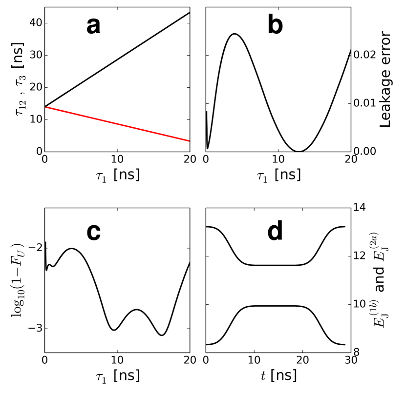
Figure 4 shows simulated numerical results of this physical two qubit interaction between transmons 1b and 2a. We use an error function shape ramping up and down, similar to Ref. Ghosh et al. (2013),
| (19) |
and = . is the idle value and is for resonant (11) and (02) states. To find optimal solutions of this form, we change and choose =. = is calculated analytically using a perturbative expression such that the whole process will result in the with desired . Figure 4a shows and the total time needed to implement a CZ gate ().
Due to the mixing with higher energy states which are out of the encoded qubit space, leakage error could pose a problem. We can compute the leakage error as follows. The full unitary operation matrix can be written in a block-form
| (20) |
where is the encoded qubit subspace and is the complementary subspace. For any qubit state in the encoded qubit space, the leaked portion is and =. = is positive definite and the leakage error can be defined as = where are the eigenvalues of . The leakage error (Fig. 4b) can be a few percent, but if we choose optimal , it can be significantly reduced, well below 1%. Note too that leakage can be dealt with algorithmically Wu et al. (2002); Fowler (2013); such circuit-based leakage reduction algorithms will likely be required in any quantum computing implementation.
Figure 4c shows the fidelity of this two-qubit unitary gate from numerical simulation of the procedure. The fidelity of the unitary gate was defined as
| (21) |
where and are the two Makhlin invariants Makhlin (2002) for two-qubit gates. Makhlin invariants are identical for different two-qubit unitary gates if they are equivalent up to single qubit operations. We find that fidelity better than 99% is achievable for ns, which also leads to very small leakage. Figure 4d shows the pulse shape of and for =10ns. The total time duration for the whole process is about 30ns. In real devices, the fidelity can be lower due to other sources of noise, but here we use only a simple form for the pulse shapes which are not fully optimized as in Refs. Martinis & Geller (2014); Ghosh et al. (2013), so there is some room for improvement. We also considered Gaussian shape pulses and obtained similar results.
We can estimate the realistic fidelity of the encoded CPHASE gate constructed here from the fidelities of the -control pulses and the adiabatic process. Since any single qubit logical gate involves at most three rotations (i.e. three pulse steps), the encoded CPHASE gate requires at most 12 pulse steps. Assuming the pulse fidelity of 0.999 and a fidelity of the adiabatic gate in Eq. (15) betweeen two transmons of about 0.99, the fidelity of the total process can be estimated to be better than . Better optimization or different sequences may improve the fidelity. Of critical comparison, the already demonstrated physical CPHASE gate fidelity of 0.99 Barends et al. (2014) also includes a single adiabatic operation and single qubit corrective operations, so the encoded CPHASE gate should be achievable with a similar fidelity. The encoded CNOT gate can be implemented with CPHASE gate and single qubit gates, and we can expect similar fidelity for CNOT gate.
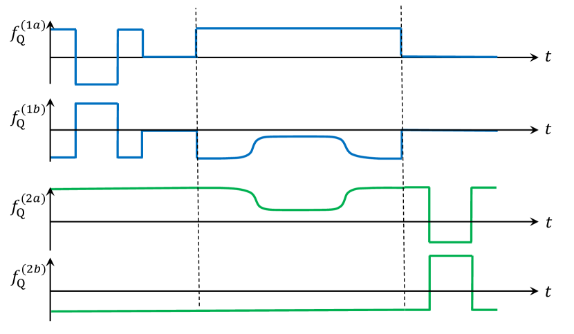
Figure 5 schematically depicts a sequence of DC pulses for the logical CPHASE gate, using the expression in Eq. (15). The first three pulses in encoded qubit 1 implement a phase gate and the next resonant pulse realizes a Pauli X gate. The second encoded qubit is pulsed to qubit frequencies such that the encoded qubit 2 rotates by to implement the identity operation. Then the two-qubit adiabatic gate between transmons and is applied. After that, an X gate is applied to encoded qubit 1 as a single resonant pulse step and a phase gate is applied to encoded qubit 2 in three rotations. This particular implementation of CPHASE contains only 9 single qubit operations, better than the general 12 single qubit gates we discussed above.
Our choice of encoded qubit is for the sake of simplicity and straightforward incorporation of physical qubit operations into logical gate operations. We also considered an alternative choice, in the same subspace, which more closely resembles choice for encoded spin qubits. With this encoded qubit, the constant capacitive coupling leads to a constant energy gap between encoded qubit states, and the control of each physical qubit allows tunable operation. Single qubit logical gates can be implemented in a similar way, and the adiabatic two qubit operation will need additional single qubit unitary gates to transform to the CPHASE gate due to the basis change of the encoded qubit.
The capacitive coupling between transmons is typically constant and determined solely by the geometry of the SC islands. This coupling is effectively turned on and off by the qubit frequency differences. With more complicated control circuits as in the gmon architecture Chen et al. (2014); Geller et al. (2015), the capacitive coupling can also be tunable and completely turned off, giving a very large on/off ratio. The tunable capacitive coupling removes the need to detune each transmon to avoid unwanted resonances, hence significantly simplifying the qubit frequency controls during the CPHASE operation. This also allows rotating the encoded qubit around any axis in the full plane, reducing the necessary rotation steps to two for any single qubit logical gates Shim et al. (2013).
I.4 Initialization
In spin systems the encoded qubit can be initialized fast and with high fidelity by loading pairs of electrons in the singlet state directly from the Fermi sea provided by the leads supplying the quantum dots, then adiabatically separating the singlet into two dots Petta et al. (2005). Electrons’ fermionic and particle nature enables this - a quantum property that may be emulated with engineered many-body photonic systems (for example, Refs. Greentree et al. (2006); Hartmann et al. (2008)), but which is in no way practical in the near term. One could also engineer a two qubit system where the ground state is a singlet, for example, by making the coupling between the 2-qubits much greater than the qubit splittings (and, e.g, waiting for relaxation to the ground state). Here, though, one would want to quickly move out of this regime in order to do gates at an implementable speed in addition to turning off as much as possible qubit-qubit couplings, which would be very challenging. Here, we provide an alternative initialization scheme that only requires fast DC pulses.
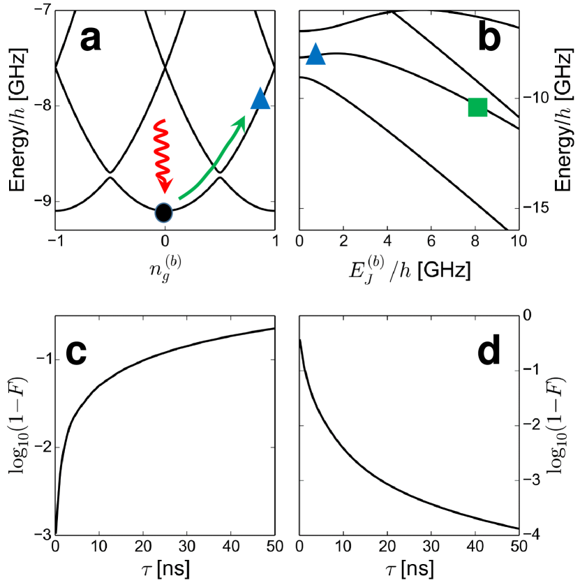
The ground state of the two transmon system is , which is not in the encoded qubit subspace defined by Eq. (3). To initialize the system into = without microwave control, we propose using a process analogous to the Landau-Zener (LZ) tunneling Landau (1932); Zener (1932). For this procedure, we need tunability of the gate charge of the second transmon, which can be provided by connecting a capacitor with a voltage control to the transmon (see Fig. 1b) or by using the side-gate for gatemons. The initialization procedure is as follows. First we tune the transmon qubit into the charge qubit regime where is much smaller than by tuning (or for a variable super-semi JJ) with . Then, via thermalization (by waiting the relaxation time or by coupling to a dissipative reservoir) the qubit reaches the ground state (black dot in Fig. 6a). (The thermalization could instead be done before tuning to the charge qubit regime.) In this charge qubit regime, the two lowest energy states anti-cross at the sweet spot =0.5. By changing the gate charge from 0 to a value larger than 0.5, we can induce the LZ tunneling to prepare the charge qubit in the first excited state (blue triangle). Then, we can tune back to the operating transmon regime () [green square in Fig.6b]. If we tune exactly to be zero, then there is a crossing instead of anti-crossing, and the fidelity will be much better. But some finite value will be allowable as long as we can change fast enough.
Figure 6c shows the calculated fidelity of the LZ tunneling in the charge qubit regime of Fig.6a as a function of the total time taken to change . Here fidelity is defined as =. We have used system parameters easily available in real systems, ==375MHz, =12GHz, =50 MHz, =30MHz. was changed from 0 to 0.8. As is the case for typical LZ tunnelings, the fidelity is better with faster change of the parameter. We expect to see fidelity better than 99% for a LZ process of a few ns. Tuning back to the transmon regime is essentially an adiabatic process, and the fidelity increases with slower change (Fig. 6d). We changed from 50MHz to 8.33GHz, and the fidelity is better than 99% for a process of a few tens of ns. So this initialization process will take 20 ns to prepare the logical qubit state with fidelity of 99%. The effect of charge and quasiparticle noise during this process is a concern that should be investigated experimentally, but charge qubits have been shown to have times up to 0.2 ms Kim et al. (2011). Variants of the flux qubit are especially stable to quasiparticle and charge noise fluctuations even at small qubit splittings Yan et al. (2015).
I.5 Measurement of the qubit states
Since an encoded qubit is in a state
| (22) |
the encoded qubit can be measured by measuring either of the physical qubits using a standard method, such as dispersive measurement Blais et al. (2003); Wallraff et al. (2004); Schuster et al. (2005); Wallraff et al. (2005) (which can be multiplexed). The choice of our encoded qubit in Eq. (3) allows us to translate the single qubit state into the encoded qubit states. With a choice of a singlet-triplet-like encoded qubit states, , the encoded qubit state can also be measured after some single qubit gates are applied to turn them into the encoded qubit states as above, or they could be measured directly by dispersive measurement since these states correspond to different resonator frequencies Gambetta et al. (2011); Srinivasan et al. (2011).
Unlike the spin system where measurement of a singlet can be done electrostatically using a projective measurement Petta et al. (2005), the dispersive measurement of SC qubits using a transmission line resonator still requires a microwave carrier, which is fine as a proof of concept. We would prefer a measurement approach that takes full advantage of our encoded qubit architecture, with qubit energy completely separated from microwave source. One possibility is to convert the encoded qubit to another quantum system (or measurement qubit) that is long-lived classically but can be read out digitally or with fast base-band pulses (in other words a latched readout), e.g., Ref. Berkley et al. (2010). A compromise option is to do dispersive measurement but still utilize lower bandwidth lines: we can either tune directly or swap the qubit with another one with a different frequency such that it can be readily measured.
II Discussion
We proposed a scheme for a “dual rail” superconducting quantum computer where each qubit consists of two tunable physical qubits. Encoded 2-qubit operations are found to require only a single physical 2-qubit gate and single qubit pulses. Since physical 2-qubit gates are typically much more costly in time and fidelity this means that the overhead of encoded operations as proposed here is not significant, especially compared to spin qubits.
In this encoded qubit architecture all qubit manipulations are achieved solely by the -control pulse sequences of individual qubits. This removes the requirement of microwave -control lines necessary in conventional transmon or similar qubit devices, simplifying classical control circuitry significantly. In addition, the encoded approach may allow lower requirements for available bandwidth per line, the potential for less crosstalk, and a reduction in needed timing accuracy as the encoded qubit states are nearly degenerate. Removing the need for microwave control frees the choice of qubit frequency from the cost and availability of microwave electronics. One is then able to design physical qubits with higher (or much lower) frequency that might enable higher temperature qubit operation (which may benefit from work already underway to enable high magnetic field compatible circuits for Majorana experiments van Woerkom et al. (2015) in higher- materials) or qubits made from degenerate quantum circuits as in symmetry protected approaches Douçot & Ioffe (2012); Kitaev (2003); Brooks et al. (2013), of which there is a natural connection to how spin qubits are inherently protected.
Encoding a qubit in a two-dimensional subspace in a larger Hilbert space introduces leakage error. For our encoded qubits, the relaxation process of individual transmons will lead to leakage out of the encoded qubit space. For a single gate operation such as CNOT of duration , the leakage error due to the process would be 0.04% for =40ns and =100s, which would slightly reduce the error threshold for quantum error correction Suchara et al. (2015). While a single gate operation of a few tens of ns does not lead to significant leakage errors, a long sequence of gate operations in a large system can be a problem. Particularly, a single logical qubit for fault-tolerant quantum computing such as the surface code will consist of many encoded qubits and a logical operation will be a sequence of operations on those encoded qubits. Therefore, leakage reduction units (LRU) Aliferis & Terhal (2007) will likely be essential. For example, a Full-LRU based on one-bit teleportation Suchara et al. (2015) would require an ancilla qubit for each encoded qubit and additional CNOT operations and measurements after each logical CNOT operation. Qubits especially designed for large relaxation times, such as variants of fluxonium Manucharyan et al. (2009), may be particularly promising for our approach (e.g., a time of 1 ms would lead to a leakage error per CNOT of 4) and would reduce the overhead for leakage mitigation dramatically.
The recently demonstrated capacitively-shunted flux qubits You et al. (2007); Yan et al. (2015) (or “fluxmon”) may also provide a promising alternative. They have comparable coherence times and a larger anharmonicity than transmons. Qubit-qubit coupling through mutual inductance would also provide transversal coupling like the capacitive coupling between transmon qubits, so the formalism used in this work should be applicable as well. They also offer benefits for initialization as they can be tuned to the flux qubit regime down to very small qubit splitting while being protected to processes that flux qubits offer, and readout can also be done by using a DC SQUID Bylander et al. (2011); Jin et al. (2015) without a transmission line.
In the next phase of this design philosophy one can consider how to mimic other beneficial properties of spin qubits: very weak coupling between qubit states to charge noise and phonons, a fast and selective two-qubit gate via a Pauli exclusion like mechanism or an interaction that mimics it, very large ON/OFF ratios, and fast initialization via some as yet unknown method.
References
- Awschalom et al. 2013 Awschalom, D. D., Bassett, L. C., Dzurak, A. S., Hu, E. L. & Petta, J. R. Quantum Spintronics: Engineering and Manipulating Atom-Like Spins in Semiconductors. Science 339, 1174–1179 (2013).
- Loss & DiVincenzo 1998 Loss, D. & DiVincenzo, D. P. Quantum computation with quantum dots. Phys. Rev. A 57, 120–126 (1998).
- Kane 1998 Kane, B. E. A silicon-based nuclear spin quantum computer. Nature 393, 133–137 (1998).
- Tyryshkin et al. 2012 Tyryshkin, A. M. et al. Electron spin coherence exceeding seconds in high-purity silicon. Nat. Mater. 11, 143–147 (2012).
- Saeedi et al. 2013 Saeedi, K. et al. Room-Temperature Quantum Bit Storage Exceeding 39 Minutes Using Ionized Donors in Silicon-28. Science 342, 830–833 (2013).
- Petta et al. 2005 Petta, J. R. et al. Coherent Manipulation of Coupled Electron Spins in Semiconductor Quantum Dots. Science 309, 2180–2184 (2005).
- DiVincenzo et al. 2000 DiVincenzo, D. P., Bacon, D., Kempe, J., Burkard, G. & Whaley, K. B. Universal quantum computation with the exchange interaction. Nature (London) 408, 339–342 (2000).
- Bacon et al. 2000 Bacon, D., Kempe, J., Lidar, D. A. & Whaley, K. B. Universal Fault-Tolerant Quantum Computation on Decoherence-Free Subspaces. Phys. Rev. Lett. 85, 1758–1761 (2000).
- Fong & Wandzura 2011 Fong, B. H. & Wandzura, S. M. Universal quantum computation and leakage reduction in the 3-qubit decoherence free subsystem. Quantum Inf. Comput. 11, 1003–1018 (2011).
- Devoret & Schoelkopf 2013 Devoret, M. H. & Schoelkopf, R. J. Superconducting Circuits for Quantum Information: An Outlook. Science 339, 1169–1174 (2013).
- Koch et al. 2007 Koch, J. et al. Charge-insensitive qubit design derived from the Cooper pair box. Phys. Rev. A 76, 042319 (2007).
- Schreier et al. 2008 Schreier, J. A. et al. Suppressing charge noise decoherence in superconducting charge qubits. Phys. Rev. B 77, 180502(R) (2008).
- Barends et al. 2013 Barends, R. et al. Coherent Josephson Qubit Suitable for Scalable Quantum Integrated Circuits. Phys. Rev. Lett. 111, 080502 (2013).
- Barends et al. 2014 Barends, R. et al. Superconducting quantum circuits at the surface code threshold for fault tolerance. Nature 508, 500–503 (2014).
- Kelly et al. 2015 Kelly, J. et al. State preservation by repetitive error detection in a superconducting quantum circuit. Nature 519, 66–69 (2015).
- Reed et al. 2012 Reed, M. D. et al. Realization of three-qubit quantum error correction with superconducting circuits. Nature 482, 382–385 (2012).
- Sun et al. 2014 Sun, L. et al. Tracking photon jumps with repeated quantum non-demolition parity measurements. Nature 511, 444–448 (2014).
- Chow et al. 2014 Chow, J. M. et al. Implementing a strand of a scalable fault-tolerant quantum computing fabric. Nat. Commun. 4, 4015 (2014).
- Córcoles et al. 2015 Córcoles, A. D. et al. Demonstration of a quantum error detection code using a square lattice of four superconducting qubits. Nat. Commun. 6, 6979 (2015).
- Blase et al. 2009 Blase, X., Bustarret, E., Chapelier, C., Klein, T. & Marcenat, C. superconducting group-IV semiconductors. Nat. Mater. 8, 375–382 (2009).
- Bustarret 2015 Bustarret, E. Superconductivity in doped semiconductors. Physica C 514, 36–45 (2015).
- Bustarret et al. 2006 Bustarret, E. et al. Superconductivity in doped cubic silicon. Nature 444, 465–468 (2006).
- Marcenat et al. 2010 Marcenat, C. et al. Low-temperature transition to a superconducting phase in boron-doped silicon films grown on (001)-oriented silicon wafers. Phys. Rev. B 81, 020501(R) (2010).
- Dahlem et al. 2010 Dahlem, F. et al. Subkelvin tunneling spectroscopy showing Bardeen-Cooper-Schrieffer superconductivity in heavily boron-doped silicon epilayers. Phys. Rev. B 82, 140505(R) (2010).
- Grockowiak et al. 2013 Grockowiak, A. et al. Superconducting properties of laser annealed implanted Si:B epilayers. Supercond. Sci. Technol. 26, 045009 (2013).
- Herrmannsdörfer et al. 2009 Herrmannsdörfer, T. et al. Superconducting State in a Gallium-Doped Germanium Layer at Low Temperatures. Phys. Rev. Lett. 102, 217003 (2009).
- Skrotzki et al. 2011 Skrotzki, R. et al. The impact of heavy Ga doping on superconductivity in germanium. Low Temp. Phys. 37, 877–883 (2011).
- Shim & Tahan 2014 Shim, Y.-P. & Tahan, C. Bottom-up superconducting and Josephson junction device inside a Group-IV semiconductor. Nat. Commun. 5, 4225 (2014).
- Shim & Tahan 2015 Shim, Y.-P. & Tahan, C. Superconducting-Semiconductor Quantum Devices: From Qubits to Particle Detectors. IEEE J. Sel. Top. Quantum Electron. 21, 9100209 (2015).
- Larsen et al. 2015 Larsen, T. W. et al. Semiconductor-Nanowire-Based Superconducting Qubit. Phys. Rev. Lett. 115, 127001 (2015).
- de Lange et al. 2015 de Lange, G. et al. Realization of Microwave Quantum Circuits Using Hybrid Superconducting-Semiconducting Nanowire Josephson Elements. Phys. Rev. Lett. 115, 127002 (2015).
- Ristè et al. 2015 Ristè, D. et al. Detecting bit-flip errors in a logical qubit using stabilizer measurements. Nat. Commun. 6, 6983 (2015).
- You et al. 2007 You, J. Q., Hu, X., Ashhab, S. & Nori, F. Low-decoherence flux qubit. Phys. Rev. B 75, 140515 (2007).
- Yan et al. 2015 Yan, F. et al. The Flux Qubit Revisited. Preprint at http://arxiv.org/abs/1508.06299 (2015).
- Makhlin et al. 1999 Makhlin, Y., Schön, G. & Shnirman, A. Josephson-junction qubits with controlled couplings. Nature 398, 305–307 (1999).
- Chang et al. 2015 Chang, W. et al. Hard gap in epitaxial semiconductor–superconductor nanowires. Nat. Nanotechonol. 10, 232–236 (2015).
- Krogstrup et al. 2015 Krogstrup, P. et al. Epitaxy of semiconductor–superconductor nanowires. Nat. Mater. 14, 400–406 (2015).
- Shim et al. 2013 Shim, Y.-P., Fei, J., Oh, S., Hu, X. & Friesen, M. Single-qubit gates in two steps with rotation axes in a single plane. Preprint at http://arxiv.org/abs/1303.0297 (2013).
- Wang et al. 2012 Wang, X. et al. Composite pulses for robust universal control of singlet–triplet qubits. Nat. Commun. 3, 997 (2012).
- Wang et al. 2014 Wang, X., Bishop, L. S., Barnes, E., Kestner, J. P. & Sarma, S. D. Robust quantum gates for singlet-triplet spin qubits using composite pulses. Phys. Rev. A 89, 022310 (2014).
- Chen et al. 2014 Chen, Y. et al. Qubit Architecture with High Coherence and Fast Tunable Coupling. Phys. Rev. Lett. 113, 220502 (2014).
- DiCarlo et al. 2009 DiCarlo, L. et al. Demonstration of two-qubit algorithms with a superconducting quantum processor. Nature 460, 240–244 (2009).
- Strauch et al. 2003 Strauch, F. W. et al. Quantum Logic Gates for Coupled Superconducting Phase Qubits. Phys. Rev. Lett. 91, 167005 (2003).
- Ghosh et al. 2013 Ghosh, J. et al. High-fidelity controlled- gate for resonator-based superconducting quantum computers. Phys. Rev. A 87, 022309 (2013).
- Wu et al. 2002 Wu, L.-A., Byrd, M. S. & Lidar, D. A. Efficient Universal Leakage Elimination for Physical and Encoded Qubits. Phys. Rev. Lett. 89, 127901 (2002).
- Fowler 2013 Fowler, A. G. Coping with qubit leakage in topological codes. Phys. Rev. A 88, 042308 (2013).
- Makhlin 2002 Makhlin, Y. Nonlocal Properties of Two-Qubit Gates and Mixed States, and the Optimization of Quantum Computations. Qunat. Inf. Proc. 1, 243–252 (2002).
- Martinis & Geller 2014 Martinis, J. M. & Geller, M. R. Fast adiabatic qubit gates using only control. Phys. Rev. A 90, 022307 (2014).
- Geller et al. 2015 Geller, M. R. et al. Tunable coupler for superconducting Xmon qubits: Perturbative nonlinear model. Phys. Rev. A 92, 012320 (2015).
- Greentree et al. 2006 Greentree, A. D., Tahan, C., Cole, J. H. & Hollenberg, L. C. L. Quantum phase transitions of light. Nat. Phys. 2, 856–861 (2006).
- Hartmann et al. 2008 Hartmann, M., Brandão, F. & Plenio, M. Quantum many-body phenomena in coupled cavity arrays. Laser Photon. Rev. 2, 527–556 (2008).
- Landau 1932 Landau, L. Zur Theorie der Energieubertragung. II. Physikalische Zeitschrift der Sowjetunion 2, 46–51 (1932).
- Zener 1932 Zener, C. Non-Adiabatic Crossing of Energy Levels. Proceedings of the Royal Society of London A 137, 696–702 (1932).
- Kim et al. 2011 Kim, Z. et al. Decoupling a Cooper-Pair Box to Enhance the Lifetime to 0.2 ms. Phys. Rev. Lett. 106, 120501 (2011).
- Blais et al. 2003 Blais, A., Huang, R.-S., Wallraff, A., Girvin, S. M. & Schoelkopf, R. J. Cavity quantum electrodynamics for superconducting electrical circuits: An architecture for quantum computation. Phys. Rev. A 69, 062320 (2003).
- Wallraff et al. 2004 Wallraff, A. et al. Strong coupling of a single photon to a superconducting qubit using circuit quantum electrodynamics. Nature 431, 162–167 (2004).
- Schuster et al. 2005 Schuster, D. I. et al. ac Stark Shift and Dephasing of a Superconducting Qubit Strongly Coupled to a Cavity Field. Phys. Rev. Lett. 94, 123602 (2005).
- Wallraff et al. 2005 Wallraff, A. et al. Approaching Unit Visibility for Control of a Superconducting Qubit with Dispersive Readout. Phys. Rev. Lett. 95, 060501 (2005).
- Gambetta et al. 2011 Gambetta, J. M., Houck, A. A. & Blais, A. Superconducting Qubit with Purcell Protection and Tunable Coupling. Phys. Rev. Lett. 106, 030502 (2011).
- Srinivasan et al. 2011 Srinivasan, S. J., Hoffman, A. J., Gambetta, J. M. & Houck, A. A. Tunable Coupling in Circuit Quantum Electrodynamics Using a Superconducting Charge Qubit with a V-Shaped Energy Level Diagram. Phys. Rev. Lett. 106, 083601 (2011).
- Berkley et al. 2010 Berkley, A. J. et al. A scalable readout system for a superconducting adiabatic quantum optimization system. Supercond. Sci. Technol. 23, 105014 (2010).
- van Woerkom et al. 2015 van Woerkom, D. J., Geresdi, A. & Kouwenhoven, L. P. One minute parity lifetime of a NbTiN Cooper-pair transistor. Nat. Phys. 11, 547–550 (2015).
- Douçot & Ioffe 2012 Douçot, B. & Ioffe, L. B. Physical implementation of protected qubits. Rep. Prog. Phys. 75, 072001 (2012).
- Kitaev 2003 Kitaev, A. Y. Fault-tolerant quantum computation by anyons. Ann. Phys. 303, 2–30 (2003).
- Brooks et al. 2013 Brooks, P., Kitaev, A. & Preskill, J. Protected gates for superconducting qubits. Phys. Rev. A 87, 052306 (2013).
- Suchara et al. 2015 Suchara, M., Cross, A. W. & Gambetta, J. M. Leakage suppression in the toric code. Quant. Inf. Comp. 15, 997–1016 (2015).
- Aliferis & Terhal 2007 Aliferis, P. & Terhal, B. M. Fault-tolerant quantum computation for local leakage faults. Quant. Inf. Comp. 7, 139–156 (2007).
- Manucharyan et al. 2009 Manucharyan, V. E., Koch, J., Glazman, L. I. & Devoret, M. H. Fluxonium: Single Cooper-Pair Circuit Free of Charge Offsets. Science 326, 113–116 (2009).
- Bylander et al. 2011 Bylander, J. et al. Noise spectroscopy through dynamical decoupling with a superconducting flux qubit. Nat. Phys. 7, 565–570 (2011).
- Jin et al. 2015 Jin, X. Y. et al. Z-Gate Operation on a Superconducting Flux Qubit via its Readout SQUID. Phys. Rev. Applied 3, 034004 (2015).
III Acknowledgements
We thank C. M. Marcus, A. Mizel, W. D. Oliver, B. Palmer, and K. D. Petersson for useful discussions.
IV Author contributions
All the authors contributed to the planning of the project, interpretation of the results, discussions, and writing of the manuscript. Y.-P.S performed the theoretical and numerical calculations.
V Additional information
Competing financial interests: The authors declare no competing financial interests.