26
Prospects of GPGPU in the Auger Offline Software Framework
Abstract
The Pierre Auger Observatory is the currently largest experiment dedicated to unveil the nature and origin of the highest energetic cosmic rays. The software framework has been developed by the Pierre Auger Collaboration for joint analysis of data from different detector systems used in the observatory. While reconstruction modules are specific to the Pierre Auger Observatory components of the framework are also used by other experiments. The software framework has recently been extended to analyze also data from the Auger Engineering Radio Array (AERA), the radio extension of the Pierre Auger Observatory. The reconstruction of the data from such radio detectors requires the repeated evaluation of complex antenna gain patterns which significantly increases the required computing resources in the joint analysis. In this contribution we explore the usability of massive parallelization of parts of the code on the GPU. We present the result of a systematic profiling of the joint analysis of the software framework aiming for the identification of code areas suitable for parallelization on GPUs. Possible strategies and obstacles for the usage of GPGPU in an existing experiment framework are discussed.
1 Introduction
Although cosmic rays have been intensively studied for more than 100 years, fundamental questions about the phenomenon remain unclear. In particular, the origin, the acceleration mechanism, and the chemical composition of the highest energetic cosmic rays with energies up to several hundred EeV (1 EeV = eV) remain open questions. As the flux of the highest energy cosmic rays is of the order of one particle per square kilometer per century, direct observation is impracticable. Instead, the Earth’s atmosphere is used as a calorimeter in which the cosmic rays are detected indirectly by the particle cascades, or ‘air showers’, they induce. For detailed reviews on cosmic rays see e.g. references [1, 2].
The currently largest detector for cosmic rays at the highest energies is the Pierre Auger Observatory in Argentina. The Pierre Auger Observatory [3] is designed as a hybrid of two complementary detector systems. The ‘surface detector’ [4] consists of 1660 water-Cherenkov stations that sample the secondary particles at the ground level. The stations are arranged in a hexagonal grid that covers an area of 3000 km2. The surface detector array is surrounded by 27 telescopes stationed at four sites to detect the fluorescence light emitted by air molecules that have been excited by the particle cascade. This ‘fluorescence detector’ [5] provides a direct calorimetric measurement independent of hadronic interaction models and thus a better energy resolution than the surface detector. Furthermore, as it measures the development of the shower in the atmosphere, it is sensitive to the mass of the primary cosmic ray. However, the fluorescence detector can operate only during clear and moonless nights, whereas the surface detector has no principal constraint on the uptime.
As complementary detector without principal time constraints, the Auger Engineering Radio Array (AERA) [6] detects the radio pulses emitted by the particle cascades, due to geomagnetic and charge-excess effects [7]. Currently, AERA consists of 124 stations in a hexagonal grid covering an area of about 6 km2. Each station is equipped with an antenna designed for polarized measurements from 30 to 80 MHz.
The Auger Software Framework [8] provides the tools and infrastructure for the reconstruction of events detected with the Pierre Auger Observatory. Components of the framework are also used by other experiments [9]. It is designed to support and incorporate the ideas of physicists for the projected lifetime of the experiment of more than 20 years. This is achieved by a strict separation of configuration, reconstruction modules, event and detector data, and utilities to be used in the algorithms. The reconstruction of radio events detected with AERA is fully integrated in the Auger Software Framework which allows joint analyses of events from all detector systems [10]. The main reconstruction algorithm for the radio reconstruction and its performance profile is described in the next section.
2 Radio Reconstruction in the Auger Offline Framework
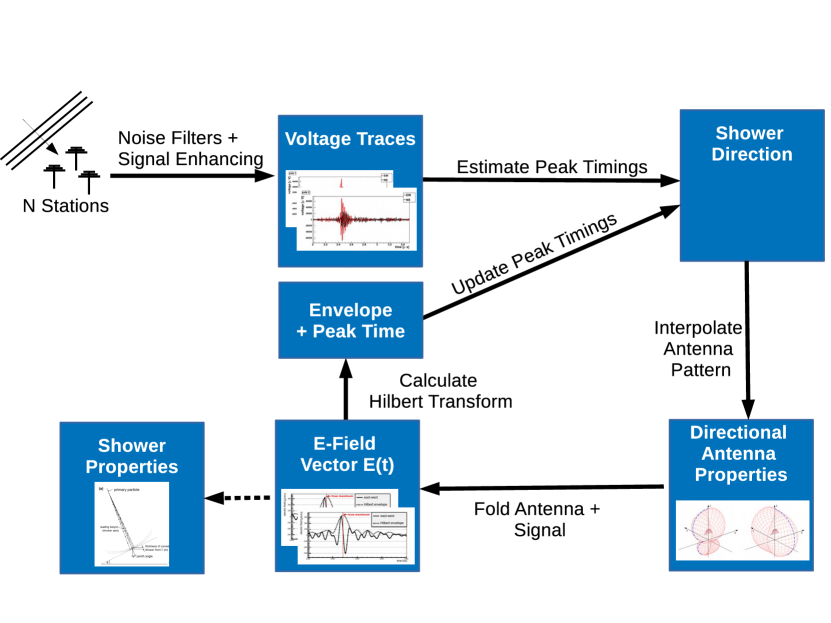
The main algorithm for the reconstruction of radio events implemented in
several modules is depicted in
Fig. 1. After a trigger, the voltage traces
of the two channels at each station are read out, and, after noise
filtering and signal enhancing, processed as follows. First, as an initial estimate of the
event timing in each station, the maxima of the voltage traces is used. Second,
from the timing information of the individual stations, the direction of the
shower is obtained by triangulation. Third, the antenna pattern for this
direction is evaluated, and the E-field trace at each station reconstructed
from the voltage traces. Finally, the maximum of the envelope of the E-field trace is
used as updated timing information for a new iteration of the procedure. On
convergence, the timing information yields the incident direction of the
primary particle whereas the E-field distribution on the ground allows
a derivation of the energy and particle type of the cosmic ray.
The execution of this algorithm in requires an uncomfortable amount of time. Using the Linux kernel profiler ‘perf’ [11] we identified two main performance bottlenecks in this algorithm. First, about 15% of the computation time is spent in calculating Fourier transformations with the FFTW library [12]. Second, about 25% of the time is used for the interpolation of the antenna patterns. All other parts of the algorithm use less than 5% of the time. The same bottlenecks are identified using ‘google-perftools’ [13] or ‘Intel VTune amplifier’ [14] as alternative profilers.
In the next sections we discuss the elimination of these bottlenecks by implementing the relevant parts on the GPU using the Cuda framework. In both cases we followed a minimum invasive approach that leaves the general interfaces in intact. To select between the CPU and GPU implementation, a preprocessor directive is used.
3 Interpolations of Antenna Patterns
To reconstruct the electric field vector from the measured voltage traces the antenna pattern in the direction of the electromagnetic wave must be known. The antenna pattern can be conveniently expressed as a two dimensional complex vector, the ‘vector effective length (VEL)’. For each antenna, the VEL is known for discrete frequencies and zenith and azimuth angles from measurements or simulations. Between theses nodes the VEL has to be interpolated for arbitrary directions.
The interpolation of textures is a core task of graphics cards, which have dedicated circuits for the interpolation. The usage of these promises a great speedup, but is available for single precision data of limited size only. In the baseline implementation, the antenna pattern is evaluated in double precision. As a linear interpolation requires six elementary operations, the maximum relative uncertainty from the limited floating-point precision can be estimated as % in single precision. This is smaller than other uncertainties in the reconstruction and thus negligible here. The largest antenna pattern considered here consists of complex data for the vector effective length at 98 frequencies, 31 zenith angles, and 49 azimuth angles. In single precision this corresponds to approximately 2.4 MB of data which is small compared to the total available memory size of a few GB on modern GPUs and much below the maximal size of a 3D texture of typically at least 204820482048 elements. The patterns for all antennas used in AERA can be stored simultaneously on the device.
To speed up the interpolation on the CPU, the pattern has already been buffered in the baseline implementation for look up on repeated access. In the GPU implementation this is unnecessary. Here, the patterns are copied and converted to allow binding to texture memory only once on first access.
4 Fourier Transformations and Hilbert Envelopes
In the baseline implementation in , calls to the FFTW library are wrapped in an object-oriented interface. The interface provides several distinct classes for the operation on real or complex data of given dimensionality. Shared functionality is implemented in a base class and propagated by inheritance. In the radio reconstruction, the wrapper operates within a container that stores a trace simultaneously in the time and frequency domains. After modification of either, the other is updated in a lazy evaluation scheme.
To calculate the FFT on the GPU, FFTW calls are replaced by calls to the CUDA FFT library (CuFFT). In contrast to the CPU implementation, all instances of the GPU implementation share static memory on the GPU to avoid time consuming allocations. This is safe here as memory copies are blocking and performed immediately before and after the FFT calculation.
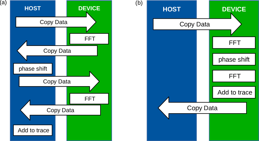
However, in the reconstruction several FFTs are calculated in context of obtaining the Hilbert envelope of the radio traces. The envelope of a trace is with the Hilbert transform of the signal . The Hilbert transformation shifts the phase of negative frequencies, i.e. for band-limited signal frequencies below the mid-frequency, by and positive frequencies by . The GPU implementation as described above thus results in a non-optimal memory access pattern for the envelope calculation as shown in Fig. 2 (a). However, with a dedicated computing kernel not only can two memory copies be avoided, but also the phase shift and summation are calculated in parallel (cf. Fig 2 (b)).
5 Discussion
The results obtained from the new GPU implementations are consistent with the results from the baseline implementation. While the FFTs yield identical results on CPU and GPU, the interpolation is not only a different implementation but also only in single precision. This amounts to a relative difference in the directional antenna patterns between the individual implementations of typically below and thus small compared to other uncertainties.
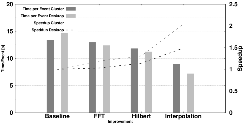
The performance improvements obtained by the modifications are summarized in Fig. 3. As test systems we used here a typical recent desktop PC and a combined CPU/GPU cluster. The desktop is equipped with an AMD A8-6600K processor and an NVIDIA GeForce 750 Ti graphics card. The cluster contains 4 Intel Xeon X5650 CPUs and 4 NVIDIA Tesla M2090 GPUs. On the desktop system the GPU implementation of FFT and the Hilbert transformation yield a speedup of 1.3, doing also the interpolations on the GPU increased this speedup to approximately 2. On the cluster system the total achieved speedup is 1.5. The lower speedup on the cluster system is due to the higher relative performance of the cluster CPU and GPU compared to the desktop system.
As only selected isolated parts of the code are moved to the GPU, the time used for computing on the GPU is low compared to the time needed for memory copy, and also only 7% of the copy-time is overlapped by computing time. However, increasing the GPU utilization would require the traces to be kept permanently on the GPU so that more analysis steps can benefit from porting to the GPU. This, however, would require non-trivial changes in the framework, in particular, modifications of the internal structure and interfaces.
6 Conclusion
The calculation of Fourier transformations and the interpolation of antenna response patterns have been identified as bottlenecks in the AERA event reconstruction using a performance profiler. Eliminating both by re-implementating the calculation in CUDA while keeping the structure of intact yields a speedup of 1.49 to 2.04 depending on the test system. The largest speedup is obtained here on a typical desktop PC equipped with an entry level graphics card. Considering the relative costs of about €500 for a desktop PC and €100 for an entry level GPU, even such selected applications of GPGPU in existing frameworks are a possibility to be considered in planning future computing strategies.
References
- [1] K. Kotera and A. V. Olinto. The astrophysics of ultrahigh energy cosmic rays. Annual Review of Astronomy and Astrophysics, 49:119–153, 2011.
- [2] A. Letessier-Selvon and T. Stanev. Ultrahigh Energy Cosmic Rays. Reviews of Modern Physics, 83:907–942, 2011.
- [3] J. Abraham et al. (The Pierre Auger Collaboration). Properties and performance of the prototype instrument for the Pierre Auger Observatory. Nuclear Instruments and Methods in Physics Research Section A, 523:50, 2004.
- [4] I. Allekotte et al. (The Pierre Auger Collaboration). The Surface Detector System of the Pierre Auger Observatory. Nuclear Instruments and Methods in Physics Research Section A, 586:409–420, 2008.
- [5] J. Abraham et al. (The Pierre Auger Collaboration). The Fluorescence Detector of the Pierre Auger Observatory. Nuclear Instruments and Methods in Physics Research Section A, 620:227–251, 2010.
- [6] J. Neuser for the Pierre Auger Collaboration. Detection of Radio Emission from Air Showers in the MHz Range at the Pierre Auger Observatory. In Proceedings of the 6th international Conference on Acoustic and Radio EeV Neutrino Detection Activities (ARENA), 2014.
- [7] A. Aab et al. (The Pierre Auger Collaboration). Probing the radio emission from air showers with polarization measurements. Phys. Rev. D, 89:052002, Mar 2014.
- [8] S. Argiro et al. The Offline Software Framework of the Pierre Auger Observatory. Nuclear Instruments and Methods in Physics Research Section A, 580:1485–1496, 2007.
- [9] R. Sipos et al. The offline software framework of the na61/shine experiment. In Proceedigs of the International Conference on Computing in High Energy and Nuclear Physics 2012 (CHEP2012), 2012.
- [10] P. Abreu et al. (The Pierre Auger Collaboration). Advanced functionality for radio analysis in the Offline software framework of the Pierre Auger Observatory. Nuclear Instruments and Methods in Physics Research Section A, A635:92–102, 2011.
- [11] The Linux Kernel Team. Perf wiki. https://perf.wiki.kernel.org/index.php/Main_Page, visited on 2014-09-19.
- [12] M. Frigo and S. G. Johnson. The design and implementation of FFTW3. Proceedings of the IEEE, 93(2):216–231, 2005. Special issue on “Program Generation, Optimization, and Platform Adaptation”.
- [13] Google Inc. gperftools - fast, multi-threaded malloc() and nifty performance analysis tools. https://code.google.com/p/gperftools/, visited on 2014-08-10.
- [14] The Intel Corporation. Intel VTune Amplifier. https://software.intel.com/en-us/intel-vtune-amplifier-xe, visited on 2014-08-02.