e-mail Svitlana.Polesya@cup.uni-muenchen.de
2 Inst. für Anorgan. Chemie, Universität Kiel, Olshausenstr. 40, 24098 Kiel, Germany
XXXX
Dzyaloshinskii-Moriya interactions and magnetic texture in the Fe films deposited on transition-metal dichalcogenides
Abstract
\abstcolThe magnetic properties of materials based on two-dimensional transition-metal dichalcogenides (TMDC), namely bulk Fe1/4TaS2 compound as well as TMDC monolayers with deposited Fe films, have been investigated by means of first-principles DFT calculations. Changing the structure and the composition of these two-dimensional systems resulted in considerable variations of their physical properties. For the considered systems the Dzyaloshinskii-Moriya (DM) interaction has been determined and used for the subsequent investigation of their magnetic structure using Monte Carlo simulations. Rather strong DM interactions as well as large ratios have been obtained in some of these materials, which can lead to the formation of skyrmionic structures varying with the strength of the applied external magnetic field.
keywords:
Dzyaloshinskii-Moriya interaction, dichalcogenide, skyrmion, two-dimensional1 Introduction
Magnetic systems with broken inversion symmetry and strong spin-orbit interaction exhibit various types of chiral magnetic texture caused by the interatomic Dzyaloshinskii-Moriya (DM) interaction, namely: helimagnetic structures, domain walls with a preferred chirality [1, 2], magnetic skyrmions, etc. 2D systems like magnetic surfaces, interfaces or deposited ultrathin films are considered as promising candidates for technological applications as they exhibit the needed properties required to stabilize skyrmionic structures, as e. g. large DM interactions and strong magnetic anisotropy. In the case of films and interfaces the properties are essentially determined by the substrate type and structure parameters, as well as by the type of of magnetic atoms.
Possible candidates for such systems are 3D transition metal dichalcogenide (TMDC) systems with quasi-2D properties, which are composed of well separated -’sandwiches’ (where is a transition element atom, and a chalcogen atom, S, Se or Te) coupled to each other due to rather weak van der Waals interactions. Crystallizing in different structure modifications they show a rich variety of interesting physical properties (mechanical, transport, optical, 2D charge-density wave (CDW) transitions, superconducting transitions) that are also strongly dependent on chemical composition [3, 4, 5]. In recent years a lot of work was devoted to hexagonal TMDC monolayer systems having outstanding properties attractive for spintronic or 2D electronics applications, e.g. the formation of direct band gap semiconductor properties of Mo and W, SOC induced valley Hall effect occurring due to the lack of inversion symmetry [6, 7, 8, 9], etc. The strong spin-orbit coupling (SOC) observed in these systems is due to the strong SOC of the heavy metal atoms. As it was demonstrated theoretically, also in bilayers systems the properties of the band gap (width, direct/indirect character) can be tuned, if the bilayers are composed artificially of different TMDC monolayers [10].
It should be noted, that most of the 3D TMDC materials as well as their monolayers discussed in the literature are non-magnetic. However, they allow intercalation by a variety of molecules or atoms [5] which can be magnetic, thereby creating a class of magnetic materials based on TMDC [11, 12, 13, 14]. In the case of TMDC surfaces or films two-dimensional magnetic systems can be created by deposition of magnetic overlayers. Because of lack of inversion symmetry in such systems one can expect strong DM interactions which can be tuned by different elements in the TMCD substrate. Even though no experimental measurements have been performed so far for these systems, it is worth to investigate their properties, in particular, their potential for skyrmion formation, to be subsequently used as a material for memory storage devices.
2 Computational details
Within the present work, spin-polarized electronic structure calculations for the ground-state have been performed using the multiple scattering KKR (Korringa-Kohn-Rostoker) Green function method [15, 16] in the scalar-relativistic approximation. The local spin density approximation (LSDA) to the exchange-correlation functional in density functional theory was used with the parametrisation of the exchange-correlation potential by Vosko, Wilk, and Nusair [17]. The potential geometry was treated within the atomic sphere approximation (ASA). For the angular momentum expansion of the Green function a cutoff of was applied. The isotropic exchange coupling parameters and components of the Dzyaloshinskii-Moriya interactions have been calculated within the Green function formalism [18]. These parameters have been used for subsequent Monte Carlo (MC) simulations based on the extended Heisenberg model [19], using the Metropolis algorithm. The structural parameters for bulk Fe intercalated Fe1/4TaS2 was taken from experiment [20], while for the TMDC monolayers with Fe overlayers the structure parameters ( and ) have been obtained within the structure optimization procedure using the VASP code [21]. More details about Fe intercalated TaS2 systems one can see in Ref. [22].
3 Results
(a)
 (b)
(b)
 (c)
(c)
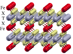
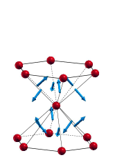
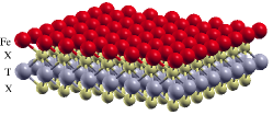
As was pointed out, the TMDC systems exhibit strong SOC effects. Therefore strong DM interactions in the materials based on TMDC without inversion symmetry can be expected, that are formed by intercalation or deposition of magnetic layers. Calculations for the Fe intercalated bulk Fe1/4TaS2 (see the structure in Fig. 1(c)) have been performed using the experimental structure parameters. Due to modifications of the electronic structure caused by the Fe intercalation the CDW instability observed for pure TaS2 is removed. The Fe spin magnetic moments obtained in our calculations for Fe1/4TaS2 is . Fig. 1(b) shows the directions of the first non-zero DM interaction, meV, between the Fe atoms which belong to different neighboring Fe layers. Within the layers the DM interaction are zero for symmetry reason. The strongest exchange interaction meV is observed for Fe atoms which belong to neighboring Fe planes, that, in turn, results in the ferromagnetic (FM) alignment of their magnetic moments. Within the planes the isotropic exchange interactions are rather small, meV. Although the DM interactions between the atoms arranged within the plane are zero, one can expect that the rather strong interlayer DM interactions leads to the formation of a pronounced magnetic texture.
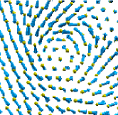
MC simulations have been performed taking into account the observed experimentally out-of-plane magnetic anisotropy in the system. No skyrmion structure has been obtained at any magnitude of magnetic field. Note, however, that an artificial rotation of the direction of the magnetocrystalline anisotropy (MCA) into the plane results in the formation of a half-skyrmion (or meron) magnetic texture. This can be seen in the snapshot of magnetic configuration (see Fig. 1(c)) obtained at 1.0 K with the MCA energy meV and external magnetic field T.
(a)
 (b)
(b)
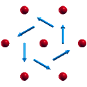
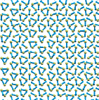
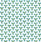
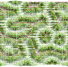
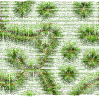
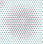
As mentioned above, one can expect strong DM interactions for 2D systems consisting of Fe overlayers on top of a TMDC monolayer. Therefore, calculations have been performed for a TaS2 monolayer with a deposited Fe overlayer. Magnetic anisotropy was not taken into account in MC simulations in the present work. In a first step, the calculations have been perfomed for an occupancy of 25% of the sites within the Fe-layer, assuming that the Fe atoms create an ordered structure similar to that observed in the intercalated systems Fe1/4TaS2. Because of the large distance between the Fe atoms within the monolayer, the isotropic interactions between the first neighboring Fe atoms within the layer are rather small, meV, and comparable to the DM interactions, meV. However, the sign of is negative, leading to a frustrated magnetic structure within the Fe layer with the Fe magnetic moments lying in the film plane. The component of the DM interaction vector is nearly zero and the DM vectors are oriented almost within the plane as it is shown in Fig. 2(a). As a result, at low temperatures the effect of the DM interaction is hardly seen Fig. 3(a). However, when the temperature increases leading to spin moment fluctuations with increasing -component of the Fe spin moments, the modulation of the magnetic structure due to the DM interactions becomes more pronounced. An external magnetic field along the direction (perpendicular to the film plane) forces the magnetic moments to be aligned parallel to the field, that, in turn, leads to a pronounced modification of the magnetic structure due to the DM interactions as is shown in 3(b).
(a)
 (b)
(b)
(c)
 (d)
(d)
(e)
 (f)
(f)
The calculations on a deposited Fe monolayer have been performed for TMDC monolayers with 1T and 1H polytypes with the atoms occupying the positions with octahedral and trigonal-prismatic coordination, respectively (see geometry for Fe/1H-TMDC in Fig. 2(b)). Some results of the calculations for the systems under considerations are presented in Table 1. As we focus here on the interatomic exchange tensor, one can see that the isotropic exchange interactions are larger while DM interactions are smaller for the Fe films deposited on 1H-TMDC monolayers when compared to the Fe/1T-TMDC system. As a result, the ratio is significantly smaller in the first case. As it follows from the calculations for Fe/1T-TMDC system, the transition from S to Te results in a decrease of values leading as a consequence to an increase of the ratio. Note that in the case of Fe/1T-WTe2 system, , and are negative and . Therefore, the values of exchange interactions are presented in Table 1 for two distances, while ratio is omitted as they do not have significant meaning in this case. The directions of DM vectors in the systems under consideration are shown in Fig. 2(a).
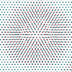
Figure 3(c)-(d) displays the results of MC simulations for Fe/1T-TaTe2 obtained at K and the external magnetic field T and T. Without field, one can see a rather complicated helimagnetic structure (similar to one obtained in [24]) in contrast to that observed for example in the case of FePt monolayers on the Pt(111) surface [23]. An increase of results in an increase of the area of FM-ordered regions with the magnetization along and a stabilization of magnetic skyrmions (having winding number one, Fig. 3(e)). In addition, one can see in Fig. 3(d) a magnetic texture with a complicated topology and with the core magnetization along the magnetic field. This texture can transform at the increasing magnetic field into the skyrmion with winding number equal to two, (see Fig. 3(f)). The following increase of , however, results in the vanishing of these types of skyrmions leading to the conventional skyrmionic structure with the skyrmion density varying with the strength of the magnetic field.
| 1H-polytype | |||||
| TaS2 | 2.81 | 2.12 | 13.71 | 0.07 | |
| TaSe2 | 2.94 | 2.15 | 10.76 | 0.06 | |
| WS2 | 2.74 | 1.98 | 19.31 | 0.03 | |
| WSe2 | 2.89 | 1.85 | 16.93 | 0.07 | |
| 1T-polytype | |||||
| TaS2 | 2.92 | 2.54 | 13.46 | 0.09 | |
| TaSe2 | 3.07 | 2.57 | 10.79 | 0.18 | |
| TaTe2 | 3.28 | 2.45 | 6.90 | 0.26 | |
| WS2 | 2.86 | 2.57 | 7.22 | 0.09 | |
| WSe2 | 3.01 | 2.67 | 7.12 | 0.17 | |
| WTe2: | |||||
| ( shell) | 3.22 | 2.51 | -0.33 | - | |
| ( shell) | 3.22 | 2.51 | -4.37 | - | |
4 Summary
We have demonstrated that rather strong DM interactions as well as large ratios can be obtained in systems based on TMCD compounds, namely Fe-intercalated bulk or monolayers with deposited Fe film. These systems are attractive candidates for spintronic applications showing large tunablity of their physical properties. This was demonstrated by showing the possibility of the formation of skyrmionic structure in these materials. A variety of properties have been obtained by changing the structure and the composition of the systems with Fe overlayers on top of TMDC monolayer. Using Fe/1T-TaTe2 film as an example with a large ratio, we have demonstrated the formation of skyrmions with a winding number two in these systems observed at certain value of the magnetic field, which disappear when the strength of magnetic field increases. As an outlook, the TMDC monolayers with antiferromagnetic oriented -metal films on both sides of TMDC can be considered as a prototype of bi-layered systems to observe antiferromagnetic skyrmions [25].
5 Acknowledgements
Financial support by the DFG via SFB 689 (Spinphänomene in reduzierten Dimensionen) is thankfully acknowledged.
References
- [1] A. Thiaville, S. Rohart, E. Jué, V. Cros, and A. Fert, EPL (Europhysics Letters) 100, 57002 (2012).
- [2] P. P. J. Haazen, E. Murè, J. H. Franken, R. Lavrijsen, H. J. M. Swagten, and B. Koopmans, Nat Mater 12, 299 (2013).
- [3] J. Wilson and A. Yoffe, Advances in Physics 18, 193 (1969).
- [4] J. Wilson, F. D. Salvo, and S. Mahajan, Advances in Physics 24, 117 (1975).
- [5] R. Friend and A. Yoffe, Advances in Physics 36, 1 (1987).
- [6] K. F. Mak, C. Lee, J. Hone, J. Shan, and T. F. Heinz, Phys. Rev. Lett. 105, 136805 (2010).
- [7] D. Xiao, G. B. Liu, W. Feng, X. Xu, and W. Yao, Phys. Rev. Lett. 108, 196802 (2012).
- [8] N. Zibouche, A. Kuc, J. Musfeldt, and T. Heine, Annalen der Physik 526, 395 (2014).
- [9] T. Heine, Accounts of Chemical Research 48, 65 (2015), PMID: 25489917.
- [10] H. Terrones, F. López-Urías, and M. Terrones, Sci. Rep. 3, 1549; DOI:10.1038/srep01549 (2013).
- [11] S. S. P. Parkin and R. H. Friend, Philosophical Magazine Part B 41, 65 (1980).
- [12] S. S. P. Parkin and R. H. Friend, Philosophical Magazine Part B 41, 95 (1980).
- [13] M. Eibschütz, S. Mahajan, F. J. DiSalvo, G. W. Hull, and J. V. Waszczak, Journal of Applied Physics 52, 2098 (1981).
- [14] H. Narita, H. Ikuta, H. Hinode, T. Uchida, T. Ohtani, and M. Wakihara, Journal of Solid State Chemistry 108, 148 (1994).
-
[15]
H. Ebert et al.,
The Munich SPR-KKR package, version 6.3,
H. Ebert et al.
http://olymp.cup.uni-muenchen.de/ak/ebert/SPRKKR, 2012. - [16] H. Ebert, D. Ködderitzsch, and J. Minár, Rep. Prog. Phys. 74, 096501 (2011).
- [17] S. H. Vosko, L. Wilk, and M. Nusair, Can. J. Phys. 58, 1200 (1980).
- [18] H. Ebert and S. Mankovsky, Phys. Rev. B 79, 045209 (2009).
- [19] L. Udvardi, L. Szunyogh, K. Palotás, and P. Weinberger, Phys. Rev. B 68, 104436 (2003).
- [20] E. Morosan, H. W. Zandbergen, L. Li, M. Lee, J. G. Checkelsky, M. Heinrich, T. Siegrist, N. P. Ong, and R. J. Cava, Phys. Rev. B 75, 104401 (2007).
- [21] G. Kresse and J. Furthmüller, Phys. Rev. B 54, 11169 (1996).
- [22] S. Mankovsky, K. Chadova, D. Ködderitzsch, and W. B. abd H Ebert, arXiv: 1507.06544v1 (2015).
- [23] S. Polesya, S. Mankovsky, S. Bornemann, D. Ködderitzsch, J. Minár, and H. Ebert, Phys. Rev. B 89, 184414 (2014).
- [24] E. Simon, K. Palotás, L. Rózsa, L. Udvardi, and L. Szunyogh, Phys. Rev. B 90, 094410 (2014).
- [25] X. Zhang, Y. Zhou, and M. Eza, arXiv: 1504.02252v1 (2015).