A new Regime of Pauli-Spin Blockade
Abstract
Pauli-spin blockade (PSB) is a transport phenomenon in double quantum dots that allows for a type of spin to charge conversion often used to probe fundamental physics such as spin relaxation and singlet-triplet coupling. In this paper we theoretically explore Pauli-spin blockade as a function of magnetic field applied parallel to the substrate. In the well-studied low magnetic field regime, where PSB occurs in the forward tunneling direction, we highlight some aspects of PSB that are not discussed in detail in existing literature, including the change in size of both bias triangles measured in the forward and reverse biasing directions as a function of . At higher fields we predict a crossover to “reverse PSB” in which current is blockaded in the reverse direction due to the occupation of a spin singlet as opposed to the traditional triplet blockade that occurs at low fields. The onset of reverse PSB coincides with the development of a tail like feature in the measured bias triangles and occurs when the Zeeman energy of the polarized triplet equals the exchange energy in the (0,2) charge configuration. In Si quantum dots these fields are experimentally accessible; thus, this work suggests a way to probe singlet to triplet relaxation mechanisms in quantum dots when both electrons occupy the same quantum dot.
Since its discovery, Pauli-spin blockade (PSB)Ono et al. (2002) has been a valuable tool for probing fundamental physics. Its use in spin to charge conversion has led to investigations of spin relaxation timesPetta et al. (2005a); Hu et al. (2012), electron spin couplings to lattice nuclear spinsJohnson et al. (2005a), and spin-orbit effectsNadj-Perge et al. (2010). PSB has also received a lot of attention from the quantum information community due to its use in read-out and initialization of various electron spin statesPetta et al. (2005b); Koppens et al. (2006); Nowack et al. (2007). The majority of studies involving PSB have focused on the low magnetic field regime. In this manuscript we investigate the qualitative behavior of PSB at all magnetic fields. In doing so we identify experimentally accessible regimes where PSB has yet to be studied and new physics is likely to be found.
In a typical double quantum dot (DQD) device two quantum dots are coupled to each other as well as to two electron reservoirs (see figure 1(a)). The dots are also capacitively coupled to one or more gate electrodes which can be used to control the dot potentials. The charge configuration of the system is characterized by a pair of numbers corresponding to the number of electrons on the left and right dot, respectively. Transport through quantum dots can be understood by considering the chemical potentials of the quantum dots, and , where denotes the total energy of the system. When the appropriate chemical potentials form a energetically downhill path between the Fermi levels of the two leads, , electron tunnelling through the device is energetically favorable and leads to current flowvan der Wiel et al. (2002). Near the charge transition, where PSB typically occurs, this condition can be expressed as for transport in the forward direction and for transport in the reverse direction. These conditions describe regions of transport known as bias triangles, with sizes proportional to the applied bias voltage, .van der Wiel et al. (2002)
For a more complete picture of transport through a DQD near the charge degeneracy we now also consider the spin state of the electrons. For transport in the forward (left to right) direction current flows via tunneling events that cycle through the charge configurations. In the reverse direction it occurs via . In both cases the first tunneling event brings an electron from a lead onto the DQD forming a two-electron system. These electrons can form one of four possible spin states, the spin singlet , or one of the three triplet states , , . In zero magnetic field, the state is typically the ground state and the three degenerate triplet states are higher in energy by the exchange energy Ashcroft and Mermin (1976). Since scales with the wavefunction overlap between the two electrons, the charge configuration of the electrons will have a large influence on the magnitude of . When in the (0,2) charge configuration, the overlap is large so is as well, whereas in the (1,1) configuration the overlap is minimal as is 111In this paper we take for simplicity. Including a finite value would not significantly affect the results of this work.. This difference in exchange between the two charge configurations is the cornerstone of PSB. It leads to a situation where although the forward interdot transition is allowed for the ground states, current does not flow. This occurs because, with , it is possible that even though conduction through the singlet states is allowed, i.e. , the interdot transition for the triplet states is forbidden, . Thus, once loaded, the can tunnel neither forward nor back until it has relaxed into a singlet state. Since the spin relaxation from a state to a state is typically long relative to the tunneling times, the measured current in the PSB region is near or below the noise floor of the measurement system. This situation truncates the size of the bias triangles in the forward bias direction, as shown in figure 1c, while leaving the triangles measured in the reverse bias direction at “full size”, as in figure 1b. This size difference is the most basic signature of PSB and has been measured by several groups in various material systemsJohnson et al. (2005b); Lai et al. (2011); Yamahata et al. (2012); Simmons et al. (2010); Koppens et al. (2005); Shaji et al. (2008); Churchill et al. (2009a); Weber et al. (2014); Liu et al. (2008); Pfund et al. (2007); Nadj-Perge et al. (2010).
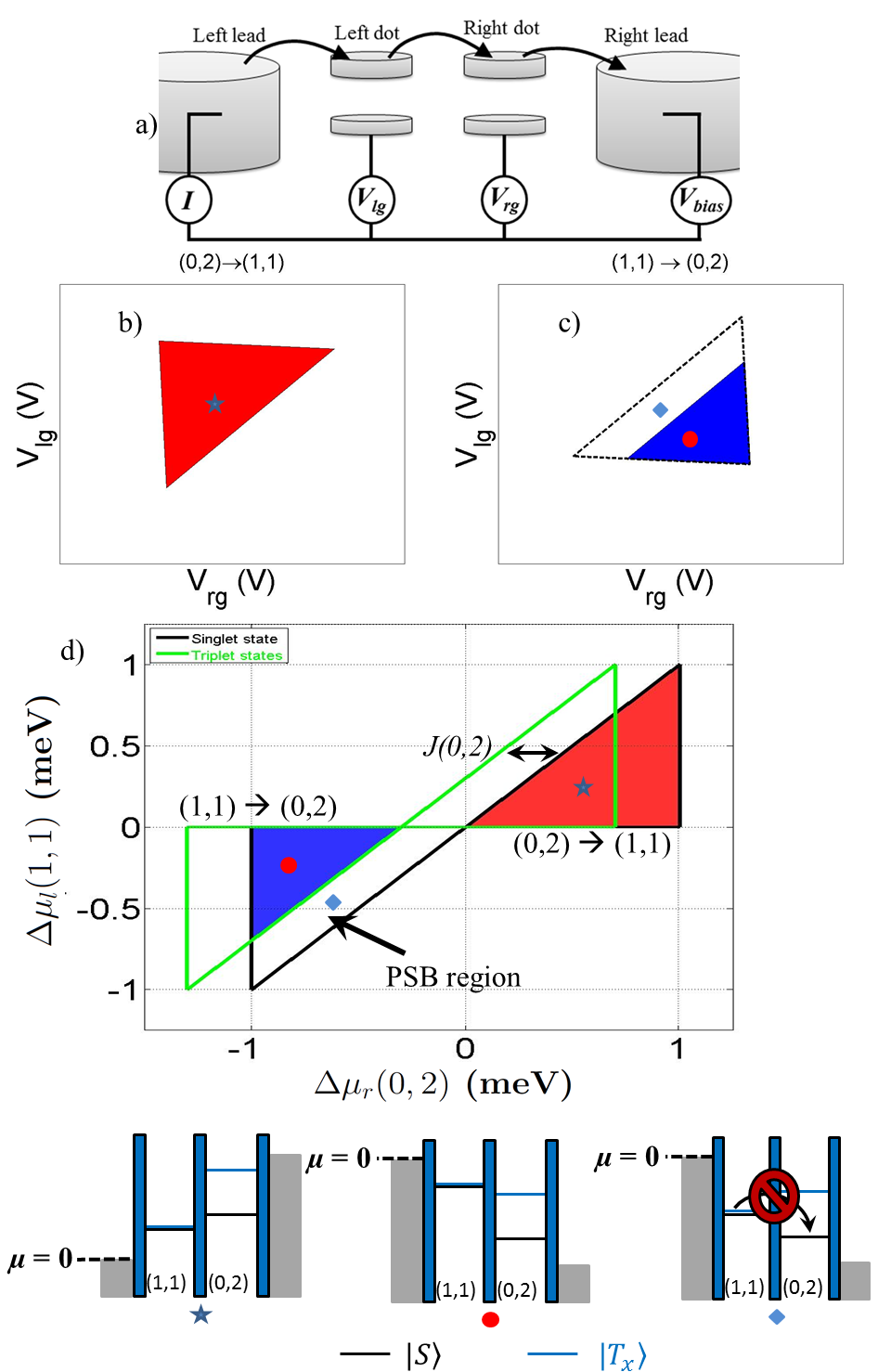
For a more intuitive presentation of the voltage space measurements depicted in figure 1(b) and (c) one can convert them to chemical potential space, or -space Perron et al. (2015), where triangles from both bias polarities can be shown on a single plot. Plotted in figure 1(d) is the -space equivalent to what is shown in both panels (b) and (c), where the axes are defined as and . Also shown in this plot are outlines of the “state triangles”, which correspond to the conditions , in the forward biased direction and , with , in the reverse direction, where refers to the spin state, or , of the two electron system. In figure 1(c) and (d), the region labeled with the blue diamond corresponds to the region where PSB occurs, as shown in the corresponding chemical potential diagram.
When a magnetic field , is applied, several effects can occur depending on the direction of the applied field. If applied perpendicular to the two-dimensional electron gas (2DEG) there can be a significant change in the spatial wavefunctions of the electrons. This will in turn affect the magnitudes of and leading to a change in size of the PSB regionJohnson et al. (2005b). At higher fields, the states can fall below the states leading to PSB in the direction caused by singlet states rather than the triplet statesSun et al. (2012). When is applied in the plane of the 2DEG the spatial effect on the wave functions is negligible and observed effects are due to the Zeeman splitting of the triplet levels. This in-plane magnetic field dependence will be the focus of the remainder of this manuscript.
When considering the in-plane , we make the following assumptions for -dependence of the chemical potentials
| (1) | ||||
| (2) | ||||
| (3) |
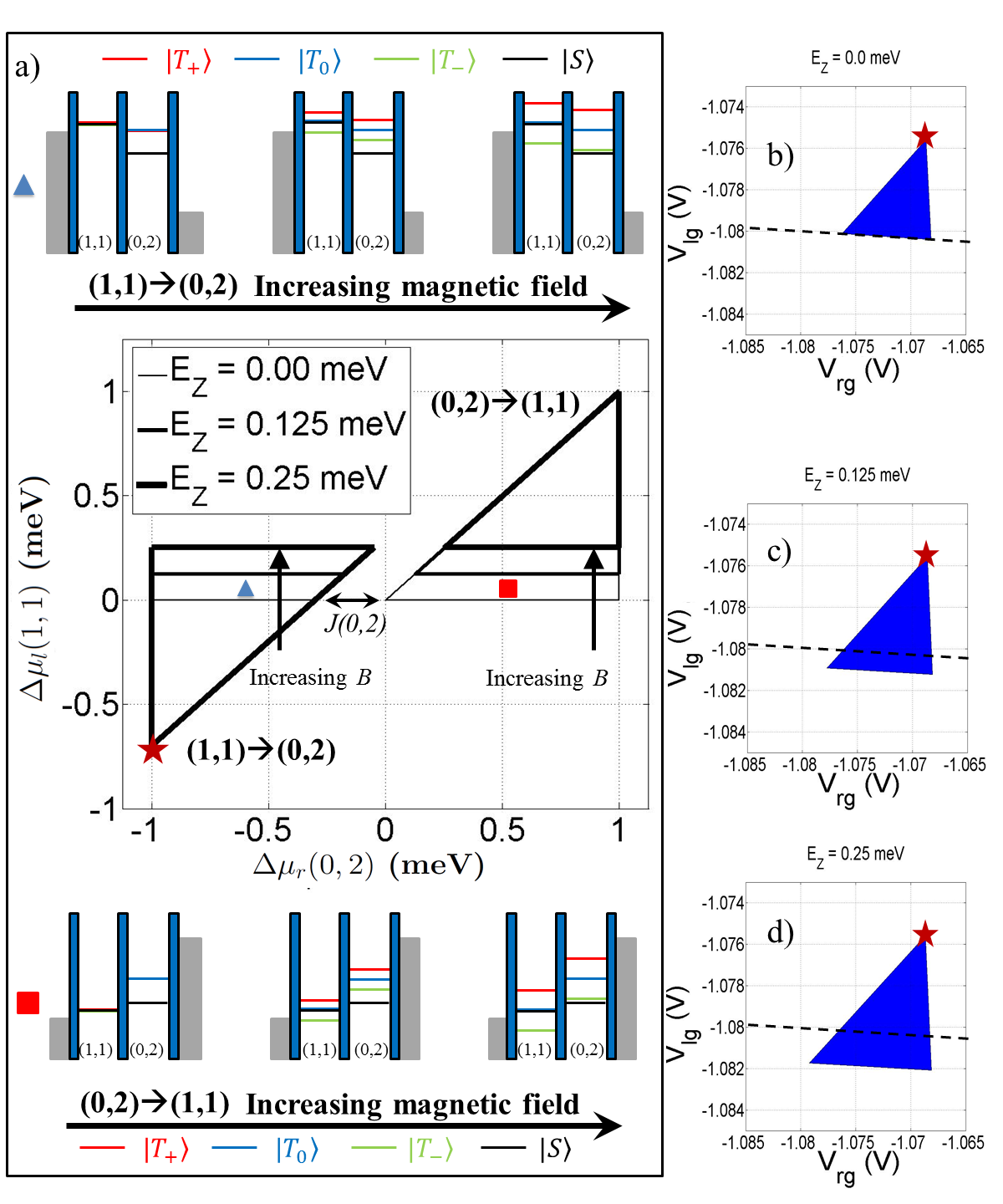
When is increased from zero, the first notable effect is the change in size of the bias triangles. As reported in reference Lai et al. (2011), the triangles in the forward biasing direction grow in size proportional to the Zeeman energy , with the electron g-factor, and the Bohr magneton. However, we predict a concomitant reduction in size of the triangles measured in the reverse direction. Both of these effects are illustrated in figure 2.
Figure 2(a) shows the -space picture of the changing triangles (see supplemental material for details on using the -space picture to determine the regions of allowed current). The origin is defined by the point where . Since has no magnetic field dependence, our definition of the origin relates it to a single point in voltage space, at all magnetic fields. This has the advantage that the direction the growth/contraction occurs along is clarified. The triangles for both biasing directions change size along the axis. This is understood by considering the process which determines the edge of the triangles in each case. For the forward direction, the crucial process is the loading of an electron from the left lead onto the left dot. As is increased, the level is lowered by the Zeeman energy meaning that the loading of that state can occur at larger values. This is shown in the chemical potential diagrams at the top of figure 2a for the point labelled with the blue triangle. In this region, since the only accessible (1,1) state is , conduction is spin-polarized. In the reverse direction, the crucial process is the Coulomb blockade of current due to loading of the level below . Again, as is increased this level drops below at a higher . This is depicted in the chemical potential diagrams at the bottom of figure 2a for the point labeled with the red square. In both biasing directions, when viewed in this -space picture, the direction the triangles are changing is clear, and we can then easily generate the correct gate voltage space picture. This is done in figure 2(b) through (d), using typical capacitance and voltage parameters, which show bias triangles for the forward direction growing with magnetic field in roughly the direction (as compared to the detuning direction i.e. perpendicular to the base of the triangles). This prediction is clearly observed in reference Lai et al. (2011) and validates the assumptions made in equations 1 through 3.
As is increased further there will be a crossover from PSB in the forward direction, as discussed above and in previous worksOno et al. (2002); Nadj-Perge et al. (2010); Liu et al. (2008); Lai et al. (2011); Yamahata et al. (2012); Johnson et al. (2005b); Koppens et al. (2005); Simmons et al. (2010); Shaji et al. (2008); Churchill et al. (2009a, b); Weber et al. (2014); Liu et al. (2008); Pfund et al. (2007); Sun et al. (2012), to PSB in the reverse direction. The onset of this reverse PSB is accompanied by the development of a tail-like feature in the regions of allowed current222These tail features are qualitatively similar to those associated with lifetime enhanced transportShaji et al. (2008); Simmons et al. (2010) but arise from very different physical mechanisms. and occurs at a magnetic field where .
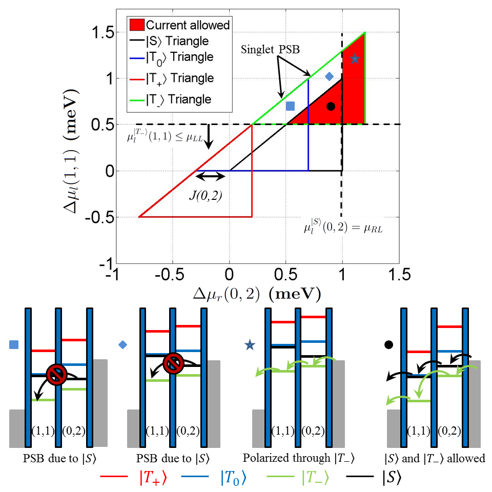
Both of the high field features can be understood by considering figure 3, a -space picture of a transport measurement in the reverse direction with . Included are the state triangles for the various singlet and triplet chemical potential levels. The regions labeled with the blue diamond and square correspond to the region of PSB. The physics of this PSB is similar to the traditional low field PSB, but with the state filling the role of the trapped state and the levels contributing to current. This is shown in the corresponding chemical potential diagrams. Throughout the PSB region, although current is allowed through the ground state levels, the state can load from the right lead and, since the tunneling event is not allowed, it will block current until it relaxes to a state. Much like how the leakage current in the low field PSB region was used to probe the relaxationLai et al. (2011); Koppens et al. (2005); Yamahata et al. (2012); Churchill et al. (2009a, b); Pfund et al. (2007); Nadj-Perge et al. (2010), leakage currents in this reverse PSB region can be used to probe the relaxation.
Figure 3 has another distinct feature, the tail region labeled with the star. This feature also develops when the state becomes the ground state in the (0,2) configuration. The feature can be understood by considering the border between the tail and the PSB region. To the left of this border no current is measured because the can load and prevent current flow as previously discussed. To the right of the border the level is above and is therefore unable to load (compare the chemical potential diagrams labelled with the diamond and the star). Since the state is the only state that can load, the current measured in the tail region will be spin polarized upon exiting the DQD, which suggests a potential use as a polarized spin current source.333The current is polarized upon exiting the double quantum dot, however, the spin relaxation process of the electrons once in the Fermi sea of the lead is likely to be fast, quickly diminishing the polarization of the current.
By thoroughly considering the -space picture typically used to explain PSB, we have identified several interesting and unexplored features involved in the transition of a double quantum dot at both low and high magnetic fields. The boundary between the two field regimes occurs at where the Zeeman energy of equals . With and exchange energies reportedLai et al. (2011); Shaji et al. (2008); Liu et al. (2008) in the range of 0.24 to 1.4 meV, in Si should be in the range of 2 to 12 Tesla, accesible with standard cryomagnetics. This suggests that Si offers an opportunity to test our predictions. Simple validation can be achieved by performing measurements of the type reported in Lai et al. (2011) for both biasing directions and comparing with our predictions of changing triangle size. Following that, the high-field tail feature we predict should be a clear signature that the reverse PSB regime has been reached. This naturally leads to experiments involving the leakage current in the PSB regime. Similar to low-field PSB leakage current investigationsLai et al. (2011); Koppens et al. (2005); Yamahata et al. (2012); Churchill et al. (2009a, b); Pfund et al. (2007); Nadj-Perge et al. (2010); Johnson et al. (2005a), these measurements would probe singlet-triplet relaxation mechanisms but in the (0,2) charge configuration rather than the (1,1). This removes any spin-orbit interaction and nuclear field gradients between the two electrons, both of which were previously shown as the dominant coupling mechanisms between the and states in certain material systemsChurchill et al. (2009a); Nadj-Perge et al. (2010); Pfund et al. (2007); Yamahata et al. (2012); Danon and Nazarov (2009); Nadj-Perge et al. (2010); Pfund et al. (2007); Churchill et al. (2009a, b); Koppens et al. (2005). Thus, measurements of this type will deepen our understanding of higher order spin relaxation mechanisms.
Acknowledgements.
We are grateful for the many useful discussions with Josh Pomeroy, Garnett Bryant, Mark Stiles and Michael Gullans.References
- Ono et al. (2002) K. Ono, D. G. Austing, Y. Tokura, and S. Tarucha, Science 297, 1313 (2002), http://www.sciencemag.org/content/297/5585/1313.full.pdf .
- Petta et al. (2005a) J. R. Petta, A. C. Johnson, A. Yacoby, C. M. Marcus, M. P. Hanson, and A. C. Gossard, Phys. Rev. B 72, 161301 (2005a).
- Hu et al. (2012) Y. Hu, F. Kuemmeth, C. M. Lieber, and C. M. Marcus, Nat Nano 7, 47 (2012).
- Johnson et al. (2005a) A. C. Johnson, J. R. Petta, J. M. Taylor, A. Yacoby, M. D. Lukin, C. M. Marcus, M. P. Hanson, and A. C. Gossard, Nature 435, 925 (2005a).
- Nadj-Perge et al. (2010) S. Nadj-Perge, S. M. Frolov, J. W. W. van Tilburg, J. Danon, Y. V. Nazarov, R. Algra, E. P. A. M. Bakkers, and L. P. Kouwenhoven, Phys. Rev. B 81, 201305 (2010).
- Petta et al. (2005b) J. R. Petta, A. C. Johnson, J. M. Taylor, E. A. Laird, A. Yacoby, M. D. Lukin, C. M. Marcus, M. P. Hanson, and A. C. Gossard, Science 309, 2180 (2005b), http://www.sciencemag.org/content/309/5744/2180.full.pdf .
- Koppens et al. (2006) F. H. L. Koppens, C. Buizert, K. J. Tielrooij, I. T. Vink, K. C. Nowack, T. Meunier, L. P. Kouwenhoven, and L. M. K. Vandersypen, Nature 442, 766 (2006).
- Nowack et al. (2007) K. C. Nowack, F. H. L. Koppens, Y. V. Nazarov, and L. M. K. Vandersypen, Science 318, 1430 (2007), http://www.sciencemag.org/content/318/5855/1430.full.pdf .
- van der Wiel et al. (2002) W. G. van der Wiel, S. De Franceschi, J. M. Elzerman, T. Fujisawa, S. Tarucha, and L. P. Kouwenhoven, Rev. Mod. Phys. 75, 1 (2002).
- Ashcroft and Mermin (1976) N. W. Ashcroft and N. D. Mermin, Solid State Physics (Thomson Learning, 1976).
- Note (1) In this paper we take for simplicity. Including a finite value would not significantly affect the results of this work.
- Johnson et al. (2005b) A. C. Johnson, J. R. Petta, C. M. Marcus, M. P. Hanson, and A. C. Gossard, Phys. Rev. B 72, 165308 (2005b).
- Lai et al. (2011) N. S. Lai, W. H. Lim, C. H. Yang, F. A. Zwanenburg, W. A. Coish, F. Qassemi, A. Morello, and A. S. Dzurak, Sci. Rep. 1 (2011), 10.1038/srep00110.
- Yamahata et al. (2012) G. Yamahata, T. Kodera, H. O. H. Churchill, K. Uchida, C. M. Marcus, and S. Oda, Phys. Rev. B 86, 115322 (2012).
- Simmons et al. (2010) C. B. Simmons, T. S. Koh, N. Shaji, M. Thalakulam, L. J. Klein, H. Qin, H. Luo, D. E. Savage, M. G. Lagally, A. J. Rimberg, R. Joynt, R. Blick, M. Friesen, S. N. Coppersmith, and M. A. Eriksson, Phys. Rev. B 82, 245312 (2010).
- Koppens et al. (2005) F. H. L. Koppens, J. A. Folk, J. M. Elzerman, R. Hanson, L. H. W. van Beveren, I. T. Vink, H. P. Tranitz, W. Wegscheider, L. P. Kouwenhoven, and L. M. K. Vandersypen, Science 309, 1346 (2005), http://www.sciencemag.org/content/309/5739/1346.full.pdf .
- Shaji et al. (2008) N. Shaji, C. B. Simmons, M. Thalakulam, L. J. Klein, H. Qin, H. Luo, D. e. Savage, M. G. Lagally, A. J. Rimberg, R. Joynt, M. Friesen, R. H. Blick, S. N. Coppersmith, and M. A. Eriksson, Nature Physics 4, 540 (2008).
- Churchill et al. (2009a) H. O. H. Churchill, A. J. Bestwich, J. W. Harlow, F. Kuemmeth, D. Marcos, C. H. Stwertka, S. K. Watson, and C. M. Marcus, Nat. Phys. 5, 321 (2009a).
- Weber et al. (2014) B. Weber, TanY. H. Matthias, S. Mahapatra, T. F. Watson, H. Ryu, R. Rahman, L. C. L. Hollenberg, G. Klimeck, and M. Y. Simmons, Nat Nano 9, 430 (2014).
- Liu et al. (2008) H. W. Liu, T. Fujisawa, Y. Ono, H. Inokawa, A. Fujiwara, K. Takashina, and Y. Hirayama, Phys. Rev. B 77, 073310 (2008).
- Pfund et al. (2007) A. Pfund, I. Shorubalko, K. Ensslin, and R. Leturcq, Phys. Rev. Lett. 99, 036801 (2007).
- Perron et al. (2015) J. K. Perron, J. M. D. Stewart, and N. M. Zimmerman, J. Phys: Condens Matter 27, 235302 (2015), specifically equations 1 and 2.
- Sun et al. (2012) Y. C. Sun, S. Amaha, S. M. Huang, J. J. Lin, K. Kono, and K. Ono, Applied Physics Letters 101, 263108 (2012).
- Churchill et al. (2009b) H. O. H. Churchill, F. Kuemmeth, J. W. Harlow, A. J. Bestwick, E. I. Rashba, K. Flensberg, C. H. Stwertka, T. Taychatanapat, S. K. Watson, and C. M. Marcus, Phys. Rev. Lett. 102, 166802 (2009b).
- Note (2) These tail features are qualitatively similar to those associated with lifetime enhanced transportShaji et al. (2008); Simmons et al. (2010) but arise from very different physical mechanisms.
- Note (3) The current is polarized upon exiting the double quantum dot, however, the spin relaxation process of the electrons once in the Fermi sea of the lead is likely to be fast, quickly diminishing the polarization of the current.
- Danon and Nazarov (2009) J. Danon and Y. V. Nazarov, Phys. Rev. B 80, 041301 (2009).